How to burn fuses so that pro mini 3.3v would go down to 1.8v [SOLVED]
-
Success! I fallowed your advice @sundberg84 and just changed boards.txt and got it to work! Simple and without custom bootloaders etc.
I will certainly forget how to do this again after few months, so here is how to burn fuses so that pro mini 3.3v would go down to 1.8v:
I just changed the boards.txt file that I found in folder c:\Program Files (x86)\Arduino\hardware\arduino\avr\boards.txtWhat I did is duplicate lines defining existing pro mini. So I searched the file for "pro mini", and there I found 4 "groups" of lines defining different pro mini boards/processors. I copied one of the groups defining Pro Mini (3.3V, 8 MHz) w/ ATmega328 and changed the name of the group from 8MHzatmega328 to (f.eks.) 8MHzatmega328bod1v8. Then change extended_fuses to 0x06 for 1.8v BOD limit. Also changed the title of the board type. The complete block looks like
## Arduino Pro or Pro Mini (3.3V, 8 MHz) w/ ATmega328 BOD at 1.7v
## --------------------------------------------------
pro.menu.cpu.8MHzatmega328bod1v8=ATmega328 (3.3V, 8 MHz, 1v7 BOD)

pro.menu.cpu.8MHzatmega328bod1v8.upload.maximum_size=30720
pro.menu.cpu.8MHzatmega328bod1v8.upload.maximum_data_size=2048
pro.menu.cpu.8MHzatmega328bod1v8.upload.speed=57600

pro.menu.cpu.8MHzatmega328bod1v8.bootloader.low_fuses=0xFF
pro.menu.cpu.8MHzatmega328bod1v8.bootloader.high_fuses=0xDA
pro.menu.cpu.8MHzatmega328bod1v8.bootloader.extended_fuses=0x06
pro.menu.cpu.8MHzatmega328bod1v8.bootloader.file=atmega/ATmegaBOOT_168_atmega328_pro_8MHz.hex

pro.menu.cpu.8MHzatmega328bod1v8.build.mcu=atmega328p
pro.menu.cpu.8MHzatmega328bod1v8.build.f_cpu=8000000L
And in my boards.txt file it starts on line 735
This is the old line for extended_fuses that we are updating/replacing
#pro.menu.cpu.8MHzatmega328bod1v8.bootloader.extended_fuses=0xFDAfter restarting Arduino IDE you should see new type of the "processor" of the board in IDE Tools menu. Select the new one we just created "ATmega328 (3.3V, 8 MHz, 1v7 BOD)" and burn the bootloader on the pro mini.
I used Arduino as ISP to burn bootloader, and there are tutorials for that on arduino.cc. If you have real ISP, then it is a bit easier, but you need to figure out your method of uploading bootloader. Check PeteB's video mentioned bellow.After that you can check that the fuzes are changed properly, by using Avrdude in the method explained in PeteB's video here https://www.mysensors.org/about/fota . You can also just try to power the mini with 2.0v and see if it works :)
This is the only time we use this newly created processor, it is not used in uploading sketches. So after bootloader is uploaded, you will be able to program pro mini "as if nothing happened", meaning you just connect FTDI and compile. But (this is very important!) dont forget to select the regular processor when uploading sketches, the "Arduino Pro or Pro Mini (3.3V, 8 MHz) w/ ATmega328", not the new one we just created. If you try using new processor, I think it will stop at compile process, so just change to regular processor.
Now you can connect the pro mini directly to batteri and have it run down to 1.8v (in theory, radio goes down to 1.9 if all is "perfect")
I just tested one sensor and it goes down to 2.0v without complaining, that is much better then 2.7 from before :)@dakipro great work and explanation. Can I use this and link from the EasyPCB site about changing BOD?
-
There's a big advantage to running with no BOD and with no external crystal (internal resonator only): under those conditions the atmega328p can wake from sleep in less than 4usec. Over time, if running from battery or a supercap, that can save you a lot of power.
-
The problem is if you have a low/no BOD and keep the 8MHz at some point the atmega won't be able to run with the low voltage. Also, it's better to run from internal oscillator instead of external (lower power consumption but less precise, so you should use it only if you do not need precise timing) and you need to have bootloader matching the fuse settings in board.txt for the frequency if you don't want your board to have all it's timing wrong.
@NeverDie reactivating BOD takes around 60uS, if we believe the datasheet. Not much to worry about IMHO, that's one minute of on time after 1 million wake ups (so, 2 years if you wake up every minute), if running at 1MHz that's around 1mA so that's a total of 1/60 = 0.016mAh for 2 years.
-
ok, my happiness was a short lasting one then :(
Is it possible to have 1MHz and low BOD, while still being able to program pro mini with ftdi? Do you @Nca78 perhaps posses such a magical bootloader?If only ISP can be used, then it makes more sense to upload FOTA enabled one, then you can at least change sketch over the air... I just didn't find 1MHz bootloader with low BOD that is fota enabled (but I could ask Tekka for help if I do not manage to make it)
@dakipro as long as you have a bootloader, then you can program using FTDI, that's the purpose of the bootloader ;)
What you are doing is programming without bootloader. If you follow the tutorial I have linked earlier and use the provided bootloader files you just have to use the "write bootloader" menu (not sure about exact text in English but it's the last item in Tools menu) to update fuses and write the bootloader on the board at the same time (based on fuses and bootloader set in boards.txt). Then you should use FTDI and not use the programmer anymore, because the programmer will erase the bootloader. -
I don't know the source but here is some interesting reading @dakipro: https://www.iot-experiments.com/arduino-pro-mini-1mhz-1-8v/
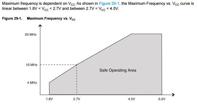
For 1.8V you need to have a maximum frequency of 4MHz.
What I have understood its a balance as well. If you have large calculations/sketches @ 1mhz it will take 8 times longer to process than 8mhz, which might even increase the battery usage since its so slow.
At the moment im running a motion detector @ 1mhz though and that code + MySensors lib has been working quick/great.
-
What are you selecting as a board when you upload sketch?
On mentioned manual it says "Choose your desired board which we have added before and burned the atmega328p with it."
But when I do that I get something likeBoard apm96 (platform avr, package arduino) is unknown Error compiling for board APM Optiboot internal 1MHz 1v8BOD 9600baud.or
Board 28PinBoard (platform avr, package arduino) is unknown
Error compiling for board atmega328p based - 28 pin DIL.
(depending on which test I try, and I tried like 10 combination of boards.txt values, fuzes and bootloaders )
When I select pro mini i IDE, i get
avrdude: stk500_recv(): programmer is not responding
avrdude: stk500_getsync() attempt 1 of 10: not in sync: resp=0x35
avrdude: stk500_recv(): programmer is not responding
avrdude: stk500_getsync() attempt 2 of 10: not in sync: resp=0x35
avrdude: stk500_recv(): programmer is not responding
avrdude: stk500_getsync() attempt 3 of 10: not in sync: resp=0x35
avrdude: stk500_recv(): programmer is not responding
avrdude: stk500_getsync() attempt 4 of 10: not in sync: resp=0x35
avrdude: stk500_recv(): programmer is not responding
avrdude: stk500_getsync() attempt 5 of 10: not in sync: resp=0x35
avrdude: stk500_recv(): programmer is not responding
avrdude: stk500_getsync() attempt 6 of 10: not in sync: resp=0x35
avrdude: stk500_recv(): programmer is not responding
avrdude: stk500_getsync() attempt 7 of 10: not in sync: resp=0x35
avrdude: stk500_recv(): programmer is not responding
avrdude: stk500_getsync() attempt 8 of 10: not in sync: resp=0x35
avrdude: stk500_recv(): programmer is not responding
avrdude: stk500_getsync() attempt 9 of 10: not in sync: resp=0x35
avrdude: stk500_recv(): programmer is not responding
avrdude: stk500_getsync() attempt 10 of 10: not in sync: resp=0x35
Problem uploading to board.  See http://www.arduino.cc/en/Guide/Troubleshooting#upload for suggestions.
When I repeat all the steps with original bootloader, it all works (I am using FTDI to upload sketches, just as nothing ha happened)
I really appreciate your help, I guess world is just not yet ready for my level of noobism, so I might as well just buy more batteries and use regular bootloader :)
@dakipro - did you see this tutorial?
-
That is the one I used, fallowed all the steps and got the results I posted above. Either it wont compile with the newly selected board (in the IDE), or it wont upload dues to getsync()-thing... I starts uploading, mini blinks 2-3 times, and then silence...
I tried with exactly what says in tutorial, then I tried with some of the bootloaders from the "collection' linked above, then I tried over 10 different combinations of similar things, different fuses and bootloaders, and nothing worked further then the errors above :( -
Success! @sundberg84 and @Nca78 you will be proud of me when I tell you that I was doing everything "correct" all the time, it is just that arudino IDE had some stupid bug or something. I had to delete everything mentioning Arduino from the pc, and reinstall the IDE, and now all works as expected!
It was a stupid thing hunting me for year(s) now that I think about it. I always assumed that ftdi cannot be used with other then the original bootloader, because of stupid error noone ever heard about :(At the end, I used this repo https://github.com/joe-speedboat/Arduino-LowPower and added new definitions in the boards.txt, then copied relevant bootloaders (and files in "variants" folder). And repeated all the steps above, and everything works great now. I have a 1mhz arduino blinking correctly, and going down to 1.8v, and sending correct temperatures and all
Life is worth living again!
Hello! It looks like you're interested in this conversation, but you don't have an account yet.
Getting fed up of having to scroll through the same posts each visit? When you register for an account, you'll always come back to exactly where you were before, and choose to be notified of new replies (either via email, or push notification). You'll also be able to save bookmarks and upvote posts to show your appreciation to other community members.
With your input, this post could be even better 💗
Register Login