What did you build today (Pictures) ?

-
I love the design of the air vent on the righthand side of your laesrcut box. Does that pattern have a name?
@neverdie nope, but it is inspired by oriental frames, I just made that based on what I saw on one of my cabinets (which I bought while living in Singapore).
-
I love the design of the air vent on the righthand side of your laesrcut box. Does that pattern have a name?
@neverdie I will publish the project once it has advanced a bit more (still need to design the PCB for this box).
-
A temp-node on 2xAA. Also a sneak-peak on EasyPCB rev 10...
@sundberg84 how is the rev10 progress going? I am about to order a batch of EasyPCB but want the new bells and whistles :-)
-
@neverdie nope, but it is inspired by oriental frames, I just made that based on what I saw on one of my cabinets (which I bought while living in Singapore).
@gertsanders Cool. You might like this pattern also then:

-
@gertsanders Cool. You might like this pattern also then:
-
@sundberg84 how is the rev10 progress going? I am about to order a batch of EasyPCB but want the new bells and whistles :-)
@mickecarlsson except I have not yet tested the new things on the back (signing and extra flash) the boards are working. I will try to test the last things before May is over and the publish.
If you want to order I can offcourse email you the Gerber's but on your own risk.
My first experience with the board is that it's performing better than Rev 9 with the new position if the hardware. Also the ground plane helps.
-
@gertsanders Cool. You might like this pattern also then:
@neverdie that is a nice pattern. I found that these things need time to draw. If anyone has a DXF file, I would love to try it.
-
@mickecarlsson except I have not yet tested the new things on the back (signing and extra flash) the boards are working. I will try to test the last things before May is over and the publish.
If you want to order I can offcourse email you the Gerber's but on your own risk.
My first experience with the board is that it's performing better than Rev 9 with the new position if the hardware. Also the ground plane helps.
@sundberg84 thanks for the offer, I can wait for the final, no worries. Do you have a list of the new components added on the back?
-
@dbemowsk said in What did you build today (Pictures) ?:
@neverdie That's cool. Kind of like an overlapping honeycomb design.
Bingo! Looks like that's exactly what it is. A small honeycomb superimposed on a bigger one.
-
@dbemowsk said in What did you build today (Pictures) ?:
@neverdie That's cool. Kind of like an overlapping honeycomb design.
Bingo! Looks like that's exactly what it is. A small honeycomb superimposed on a bigger one.
@neverdie I created that basic pattern in OpenSCAD.
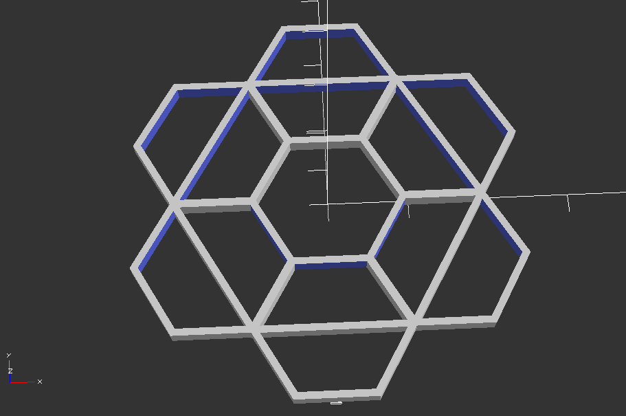
Here is the scad
$fn = 6; fudge = 0.01; pi=3.1415926; large_diameter = 40; circumradius = large_diameter/2; inradius = circumradius/(2*tan(180/$fn))-1; height = 2; line_width = 1; rotate([0, 0, 0]) hollow_cylinder(large_diameter-line_width, height, line_width); for(i=[1:$fn]) { rotate([0, 0, (360/$fn*i)+30]) translate([inradius, 0, 0]) rotate([0, 0, 30]) hollow_cylinder(circumradius, height, line_width); } module hollow_cylinder(diameter=10, thickness=2, line_thickness=2) { difference() { cylinder(thickness, d=diameter); translate([0, 0, -fudge/2]) cylinder(thickness+fudge, d=diameter-(line_thickness*2)); } } -
Expanding on that, I mapped it out further to give people an idea of how it's calculated.
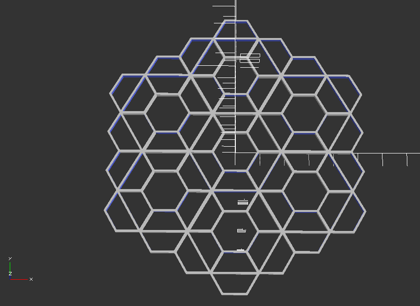
And the scad based on my previous post.
$fn = 6; fudge = 0.01; pi=3.1415926; large_diameter = 40; circumradius = large_diameter/2; inradius = circumradius/(2*tan(180/$fn))-1; height = 2; line_width = 1; for(i=[1:$fn]) { rotate([0, 0, (360/$fn*i)+30]) translate([inradius*2, 0, 0]) rotate([0, 0, 30]) honeycomb(); } module honeycomb() { rotate([0, 0, 0]) hollow_cylinder(large_diameter-line_width, height, line_width); for(i=[1:$fn]) { rotate([0, 0, (360/$fn*i)+30]) translate([inradius, 0, 0]) rotate([0, 0, 30]) hollow_cylinder(circumradius, height, line_width); } } module hollow_cylinder(diameter=10, thickness=2, line_thickness=2) { difference() { cylinder(thickness, d=diameter); translate([0, 0, -fudge/2]) cylinder(thickness+fudge, d=diameter-(line_thickness*2)); } } -
@sundberg84 thanks for the offer, I can wait for the final, no worries. Do you have a list of the new components added on the back?
@mickecarlsson - sure.
Signing: atsha204a (sot-32-3), R4: 1k-100k resistor (0805), C5 0,1uF capacitor (0805)
Flash: R7: 56k-100k resistor (0805), C7; 0,1uF capacitor (0805), U5: AT25DF512C or equivalent SPI Serial Flash Memory (8-lead SOIC). I bought this from Germany (but not tested) -
Yesterday I tested the new EasyPCB with RFM radio and hardware signing. Worked out as expected and I'm going to release all files soon.
I haven't tested the flash part yet but I'm hoping this is working as well.
This picture will be a part of a new video with me building my new RFM69 serial gateway using signing.
Anyone they can guess which issue I had when I took the photo?
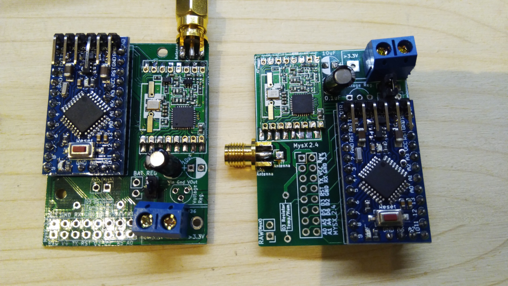
Rev9 vs Rev10 (inkl signing) rfm gw -
Yesterday I tested the new EasyPCB with RFM radio and hardware signing. Worked out as expected and I'm going to release all files soon.
I haven't tested the flash part yet but I'm hoping this is working as well.
This picture will be a part of a new video with me building my new RFM69 serial gateway using signing.
Anyone they can guess which issue I had when I took the photo?
Rev9 vs Rev10 (inkl signing) rfm gw@sundberg84 the RFM69 is soldered 180 degrees wrong on the new board :white_frowning_face:
-
@sundberg84 the RFM69 is soldered 180 degrees wrong on the new board :white_frowning_face:
@mickecarlsson interesting thought but no because the radio on rev9 isn't soldered in the image (but wrong rotated as you noticed). The hardware on that image is working. I added a HW radio without noticing so with the old code I just got no reply/Nack. I had to add the HW define.
-
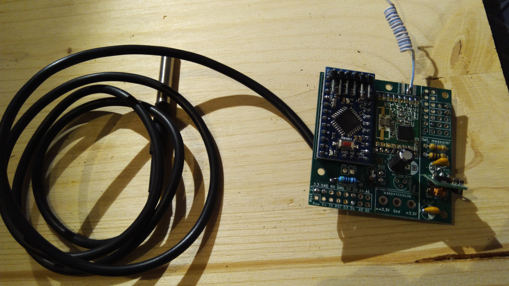
Redesigning my nodes in the RFM69 network to be signed using EasyPCB 10. Today it was my beer cooler node (because it's very important the beer temperature is secured). In the same time I'm implementing @gohan idea with two temp points (top and bottom).
-
Today I finally finished my second RGB LED lighting in the room. Next is the LED illumination of the perimeter of the bed. Under the bed, I want to place a motion sensor so that it reacts when I get out of bed at night.

you could use this under the bed:
It works like an infrared sensor (same three pins), but it does not need a line of sight. It just reacts to movement as this results in a disturbance in the emitted radio signal. Works very well on my clock :-)
The "high" value when movement is detected is not a full 5V, so I test the Out pin as an analog pin. Anything above 2.5V is an activation due to movement.
-
you could use this under the bed:
It works like an infrared sensor (same three pins), but it does not need a line of sight. It just reacts to movement as this results in a disturbance in the emitted radio signal. Works very well on my clock :-)
The "high" value when movement is detected is not a full 5V, so I test the Out pin as an analog pin. Anything above 2.5V is an activation due to movement.
@gertsanders many thanks!:raised_hands: This is very interesting, I did not previously hear about such a sensor.
I understand correctly that it can be placed in a wooden case and it can work through it? Since the tree does not reflect its waves.
If this is so, will not it respond to the movement of the bed frame or my movements when I'm on the bed?...:thinking_face:
Hello! It looks like you're interested in this conversation, but you don't have an account yet.
Getting fed up of having to scroll through the same posts each visit? When you register for an account, you'll always come back to exactly where you were before, and choose to be notified of new replies (either via email, or push notification). You'll also be able to save bookmarks and upvote posts to show your appreciation to other community members.
With your input, this post could be even better 💗
Register Login