What did you build today (Pictures) ?

-
@Yveaux I get it from the polish suplier (https://hurtowniaimport.pl/291-bb1-uchwyt-magnetyczny-samochodowy-do-telefonu-gps.html) but if you google for "magnetic phone holder 360" You wil get similar mounts.
-
-
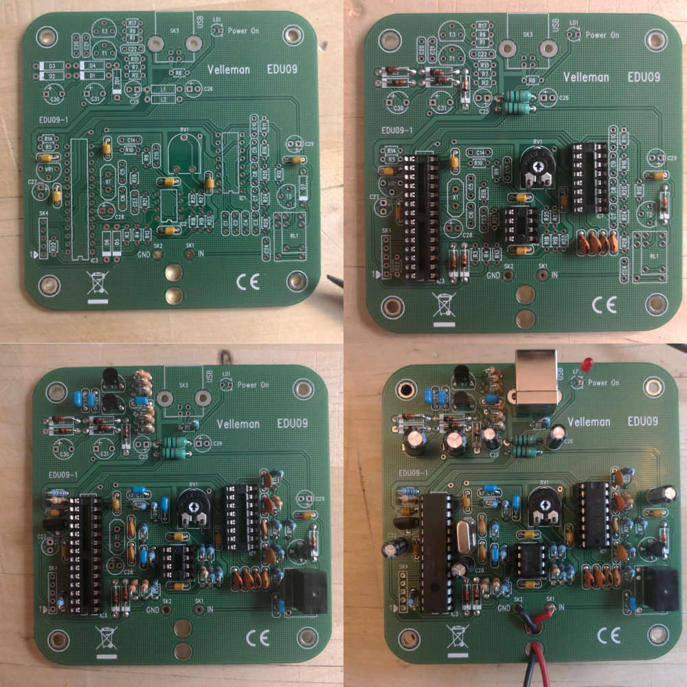
Today I soldered the Velleman EDU09 oscilloscope kit. The kit is quite cheap (~50 EUR in local store). The specs aren't impressive (max 200kHz and min 100mV/division) but hopefully it can help me learn how to use a scope before I buy a real one. -
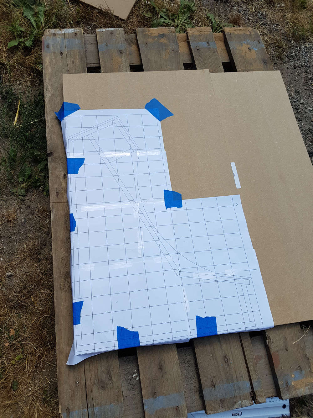
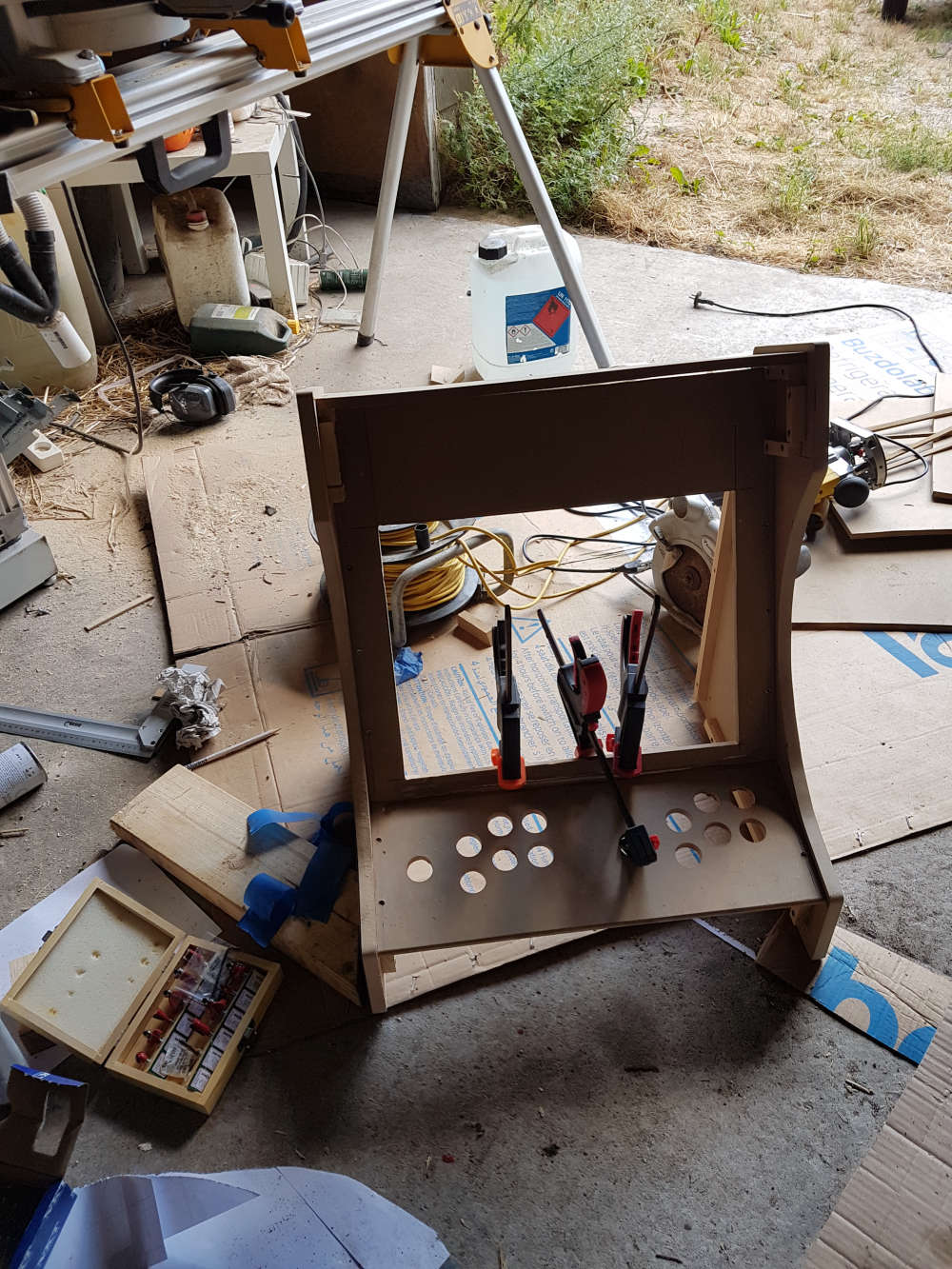
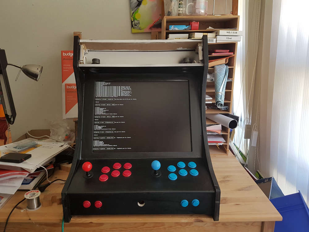
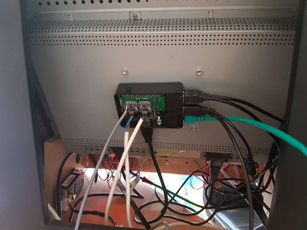
Not at all mysensors related, but I have been busy building a bartop mame cabinet the last week or so.. Still mis a couple of details, but it is in a "playable" state right now.
The setup is using an old 19" lcd monitor that I had in surplus with a RPI-3B on the back, a couple of cheap Chinese arcade controllers, a partly homebuild audio hat for the rpi (adafruit i2s 3W amplifiers), and a switchmode capable of 5V @8A (if I remember right), and 12V @3A. So I have power for the marque lighting as well..
Only game available right now is Bubble Bobble, and the kids loves it (as seen in the video linked to below).
-
For this project box that I'm making (actually printing it as I type this), I found an easy way to add ventilation: use a hex infill and turn off the upper and bottom layers.
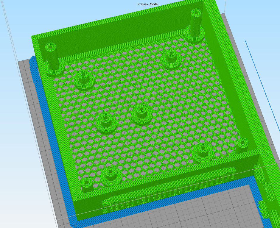
As you can see, it can still have standoffs for screwing down a PCB and for securing a lid. -
Here's the finished unit:
What it does is completely eliminate the audible PWM noise from the fan on the Prusa I3 MK3. Now it can run practically silent. :) -
Today I soldered the Velleman EDU09 oscilloscope kit. The kit is quite cheap (~50 EUR in local store). The specs aren't impressive (max 200kHz and min 100mV/division) but hopefully it can help me learn how to use a scope before I buy a real one.@mfalkvidd Just a tip. You may be better of buying this one:
Much better spec and the price is the same. AND you can save tons of time as it does not require soldering.
-
Not at all mysensors related, but I have been busy building a bartop mame cabinet the last week or so.. Still mis a couple of details, but it is in a "playable" state right now.
The setup is using an old 19" lcd monitor that I had in surplus with a RPI-3B on the back, a couple of cheap Chinese arcade controllers, a partly homebuild audio hat for the rpi (adafruit i2s 3W amplifiers), and a switchmode capable of 5V @8A (if I remember right), and 12V @3A. So I have power for the marque lighting as well..
Only game available right now is Bubble Bobble, and the kids loves it (as seen in the video linked to below).
-
@mfalkvidd Just a tip. You may be better of buying this one:
Much better spec and the price is the same. AND you can save tons of time as it does not require soldering.
-
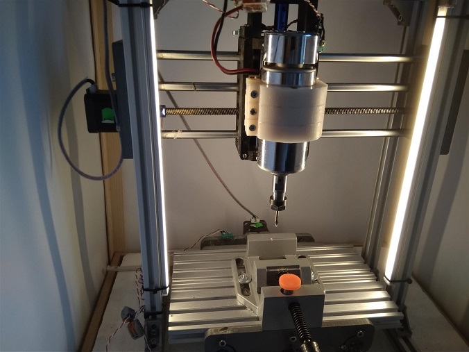
LED backlight for my CNC machine....
-
Today I've been trying to get a MS5803_05BA sensor working. This is a pressure sensor that is commonly used in dive computers.
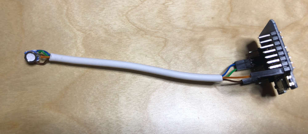
The sensor is tiny and handles 0-5 bar. So far I've not been able to communicate with it though. I use i2c and have tried two libraries, but none of them work (or maybe I killed the sensor when I soldered the cable).
-
At first I had a 25m cable. Turns out i2c isn't designed for that. It is designed for ~1m at 100kHz and ~10m at 10kHz. ESP8266 defaults to 400kHz and can't go lower than 50kHz without modifying the ESP8266 core files.
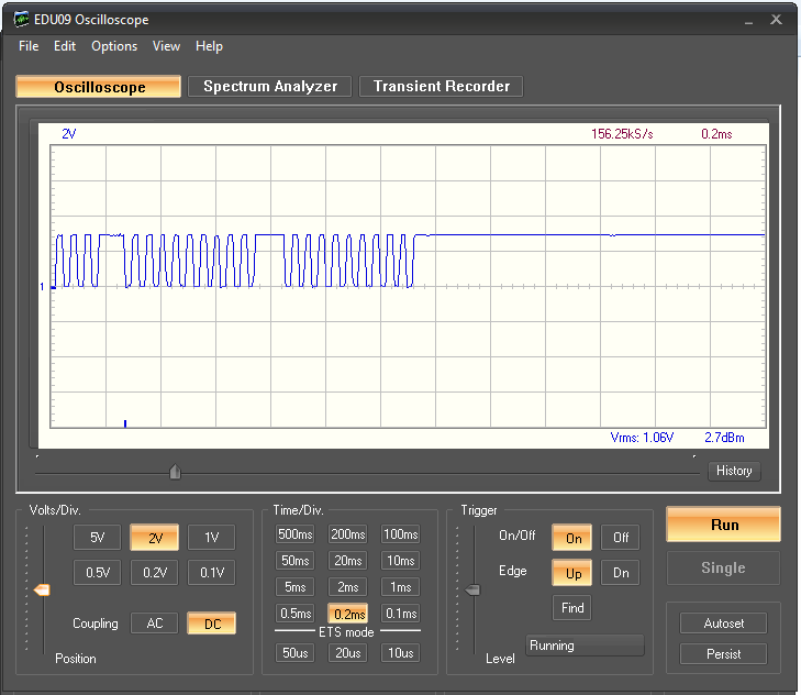
I got my first use case for the oscilloscope I built.
This was the signal at the start of the cable:
This was the signal at the end of the cable:
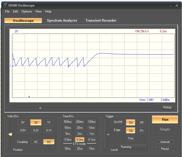
So no surprise that the communication didn't work.
I tried with a 2k pullup:
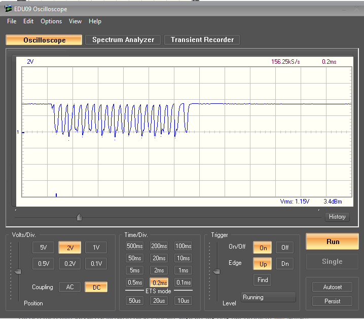
Much better! But still not very good.
I modified the library to use 7.5kHz:
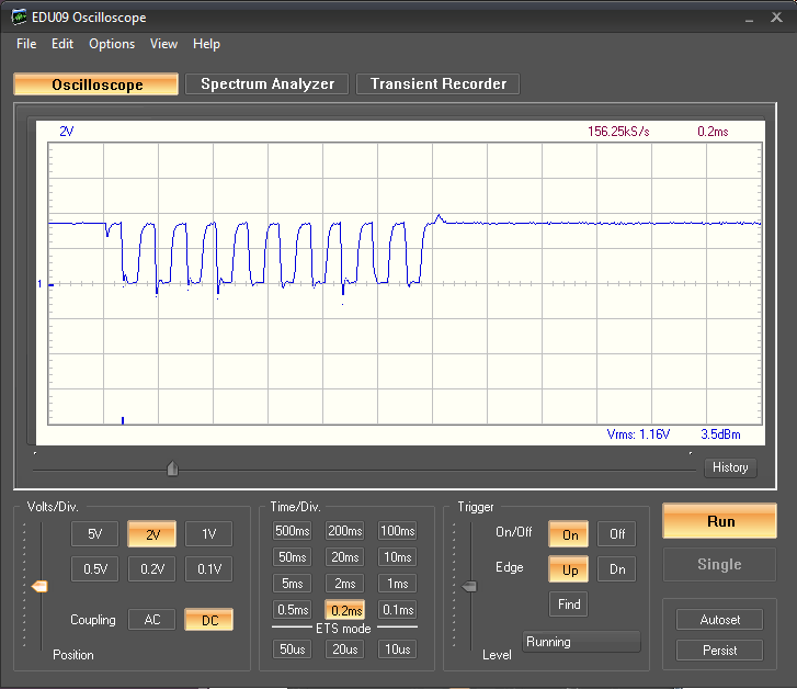
Better again, but still not great. I lowered the speed to 0.75kHz:
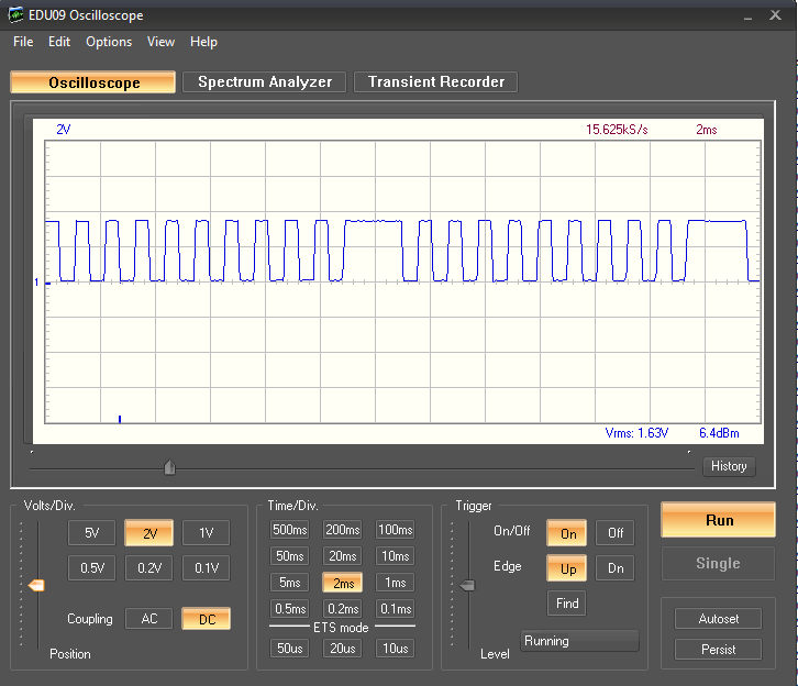
Nice and clean!
But communication still didn't work so I decided to cut the cable (to the 10cm length seen above) and restore all my changes. But communication still doesn't work.
I bought the sensor from a reputable distributor in UK so I don't think I got a faulty sensor. But I don't seem to get any life signs at all from it. I tried an i2c scan sketch and it found nothing.
-
At first I had a 25m cable. Turns out i2c isn't designed for that. It is designed for ~1m at 100kHz and ~10m at 10kHz. ESP8266 defaults to 400kHz and can't go lower than 50kHz without modifying the ESP8266 core files.
I got my first use case for the oscilloscope I built.
This was the signal at the start of the cable:
This was the signal at the end of the cable:
So no surprise that the communication didn't work.
I tried with a 2k pullup:
Much better! But still not very good.
I modified the library to use 7.5kHz:
Better again, but still not great. I lowered the speed to 0.75kHz:
Nice and clean!
But communication still didn't work so I decided to cut the cable (to the 10cm length seen above) and restore all my changes. But communication still doesn't work.
I bought the sensor from a reputable distributor in UK so I don't think I got a faulty sensor. But I don't seem to get any life signs at all from it. I tried an i2c scan sketch and it found nothing.
-
@mfalkvidd shot in the dark ; do you pull the PS pin high to select i2c protocol?
@yveaux yes I do. I took the easy way: soldered the 3.3V wire to pads 5 and 6 at the same time.
And I have tried putting a 104 ceramic capacitor between 3V3 and GND right next to the sensor.
CSB is connected to GND.My next step is either to see if I can get SPI working (instead of i2c), or order a new sensor. But first sleep.
-
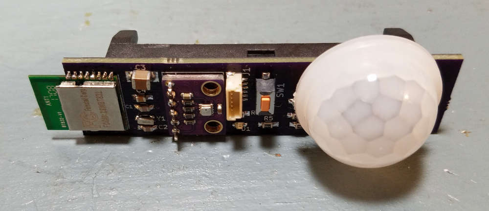
BT832 Thin Node prototype. Inspired by https://forum.mysensors.org/topic/2067/my-slim-2aa-battery-node and @neverdie nrf5 and am612 research. I noticed the BT832 is about the same width as a AA battery holder. I'm using one AA LiFePo4. This is my first sensor with nrf5, bme280, and am612. I also incorporated a jst-sh 6 pin connector for programming. It includes swd, power, and text. All sensors are working. It did not turn out to be very thin. Need to try some smaller PIR lenses and rearrange components for the next iteration.
-
Nice work! If you want to go thinner, you may have to use a coincell. Looks nice the way it is though.
-
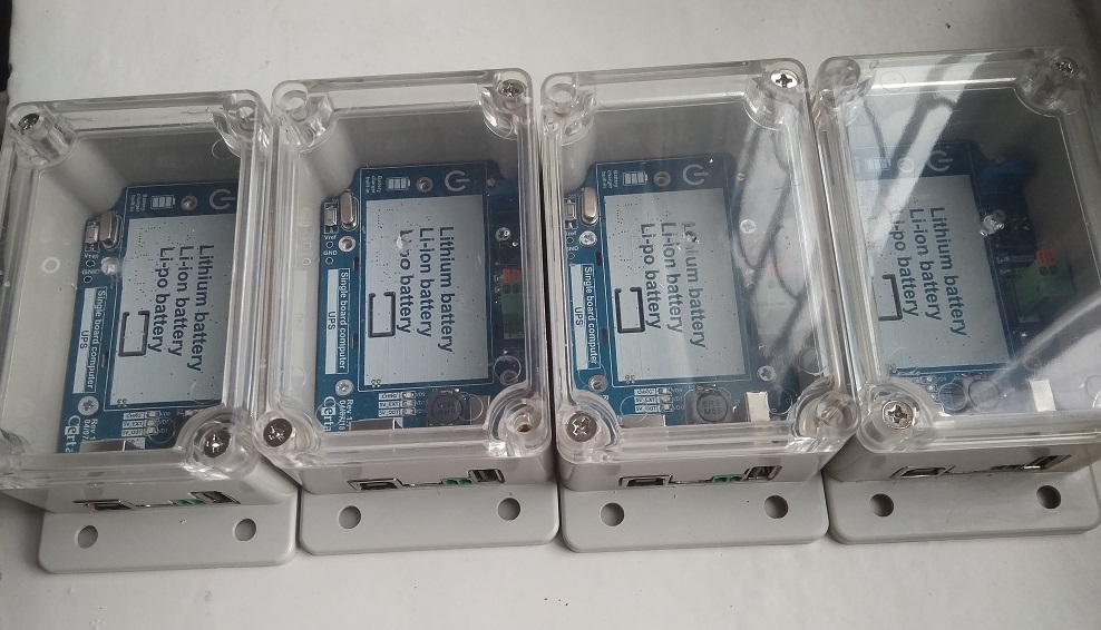
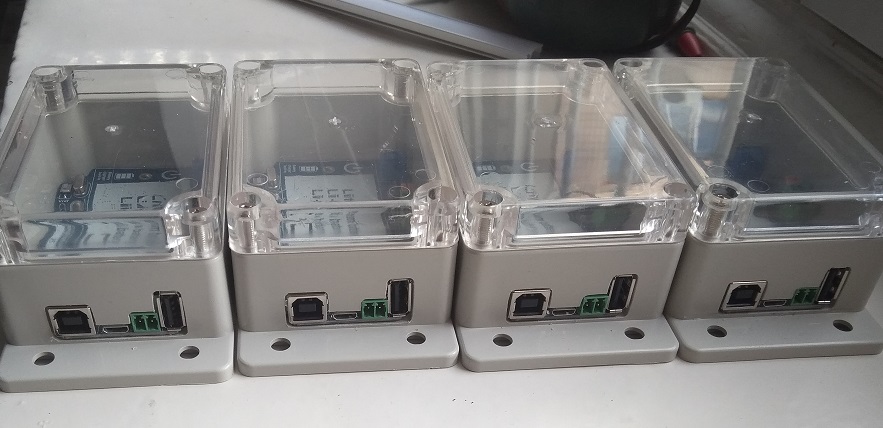
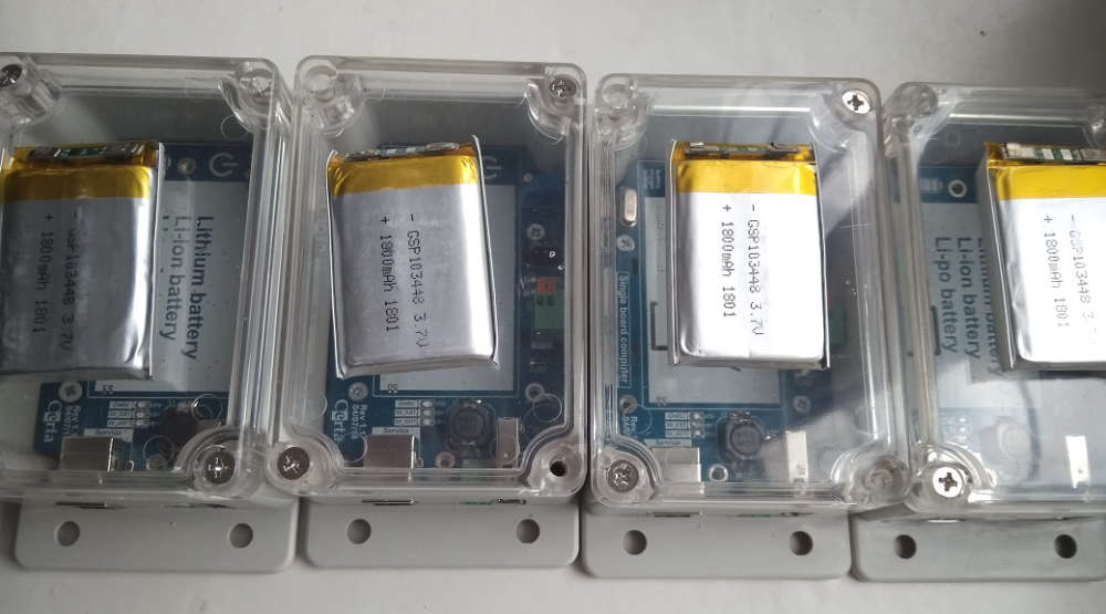
I have assembled a few UPS ... now I am testing these hardware.
Hello! It looks like you're interested in this conversation, but you don't have an account yet.
Getting fed up of having to scroll through the same posts each visit? When you register for an account, you'll always come back to exactly where you were before, and choose to be notified of new replies (either via email, or push notification). You'll also be able to save bookmarks and upvote posts to show your appreciation to other community members.
With your input, this post could be even better 💗
Register Login