What did you build today (Pictures) ?

-
@sundberg84 just a suggestion; wouldn't it be good to move the batteries to the right (instead of the left) so they block the nrf antenna less?
@mfalkvidd - a great suggestion! It wont not block it completely but as you say, a little less.
-
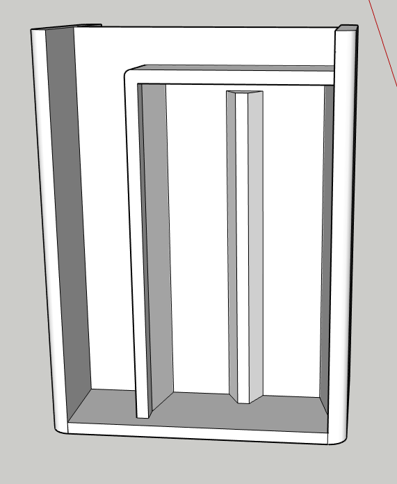
Here's another idea too: if you were to add a blank copper cladded FR4 between the batteries and the PCB above it, with a cut-out below where the antenna is, then maybe you'd have a much improved ground plane, making your radio awesome? You could have little drawer like grooves on the side of your case to slide the copper cladded FR4 into position, and, of course, you would want a ground connection to it.
-
Not sure about that groundplane @NeverDie - you are most probably right but I dont really understand the theory behind it but sounds really cool!
-
Not sure about that groundplane @NeverDie - you are most probably right but I dont really understand the theory behind it but sounds really cool!
@sundberg84 Here's all the theory you need in one picture:

Most of the modules use a monopole antenna, and as near as I can tell, most of them, if not all of them, have insufficient ground plane. It still works, of course, but it's impaired over what it would be with a better ground plane. I think maybe that's why whenever someone switches to a dipole antenna they generally notice a huge improvement. So, there's always that, but your design is nice because it's so compact, and a dipole would spoil that. -
@sundberg84 Here's all the theory you need in one picture:
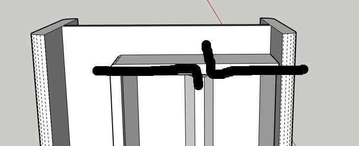
Most of the modules use a monopole antenna, and as near as I can tell, most of them, if not all of them, have insufficient ground plane. It still works, of course, but it's impaired over what it would be with a better ground plane. I think maybe that's why whenever someone switches to a dipole antenna they generally notice a huge improvement. So, there's always that, but your design is nice because it's so compact, and a dipole would spoil that.@NeverDie - so a ground plane like in here? Like that mod Pete did in his video but you inmplement it into the 3d case?
-
Yeah, the flat piece that the red line points to. I'm not sure what those black spray painted things are, so I'm ignoring those.
-
Made a dead-bug op-amp circuit to help measure open-circuit voltages created by nano-amp currents generated by a solar cell illuminated by just 1 lux of very dim light:
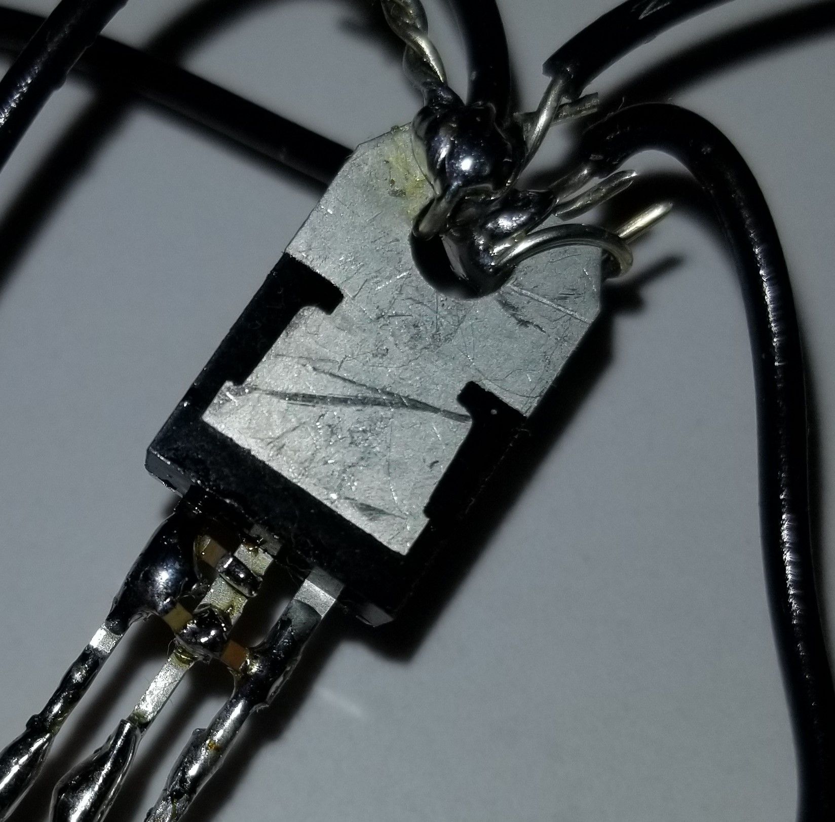
This picture is actually just the LDO part of the op-amp circuit, where I was able to solder the prescribed surface mount capacitors directly between its pins. The larger circuit is described on this thread: https://forum.mysensors.org/topic/10812/the-harvester-ultimate-power-supply-for-the-raybeacon-dk/122
Why dead-bug you ask? Since the circuit depends on the correct measurement of the effects of mere nanoamps, I didn't want any leakage currents that might happen on a protoboard, which can be significant when it's just a small number of nanoamps and their effects that's under scrutiny. -
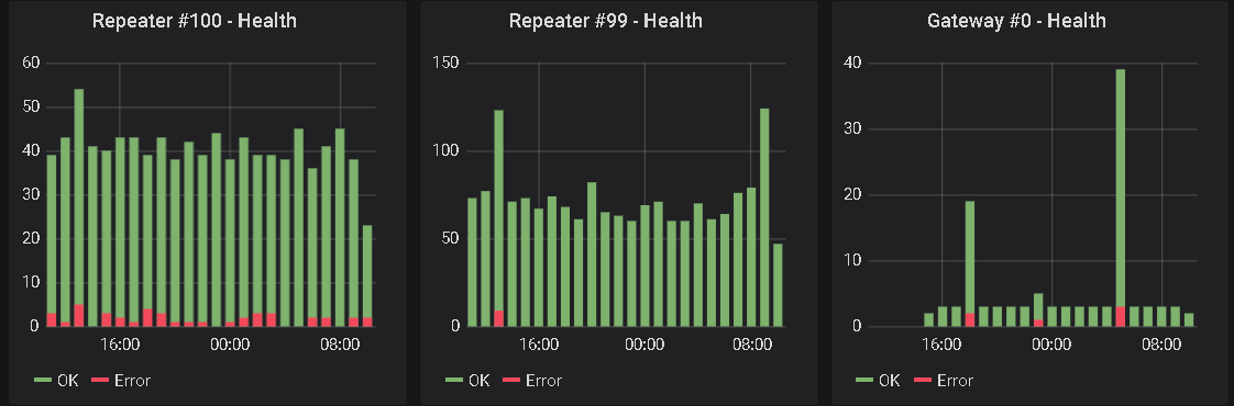
Updated my GW with the code @mfalkvidd provided to monitor OK and NACK
-
I got tired of twisting DuPont cabels to get from different programmers to different boards.
This is an adapter that lets me connect the programmers I commonly use (Jlink-mini, BMP, STLink clone) with the boards I commonly program with straight through wires. I left a couple unpopulated for future in and out.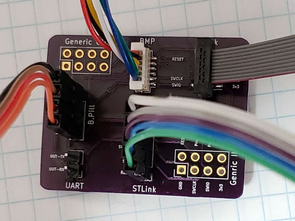
-
Finally I am starting to do a little electronics again.. First thing is a prototype assembly of RASLE (Rpi Arcade Sound and Light Extension). It's a custom made arduino "coprocessor" for a raspberry pi, built into retropie arcade cabinets. It's a joint project with a couple of friends that are building arcade cabinets (I built mine a couple of years ago, I think that there is pictures earlier in this thread).
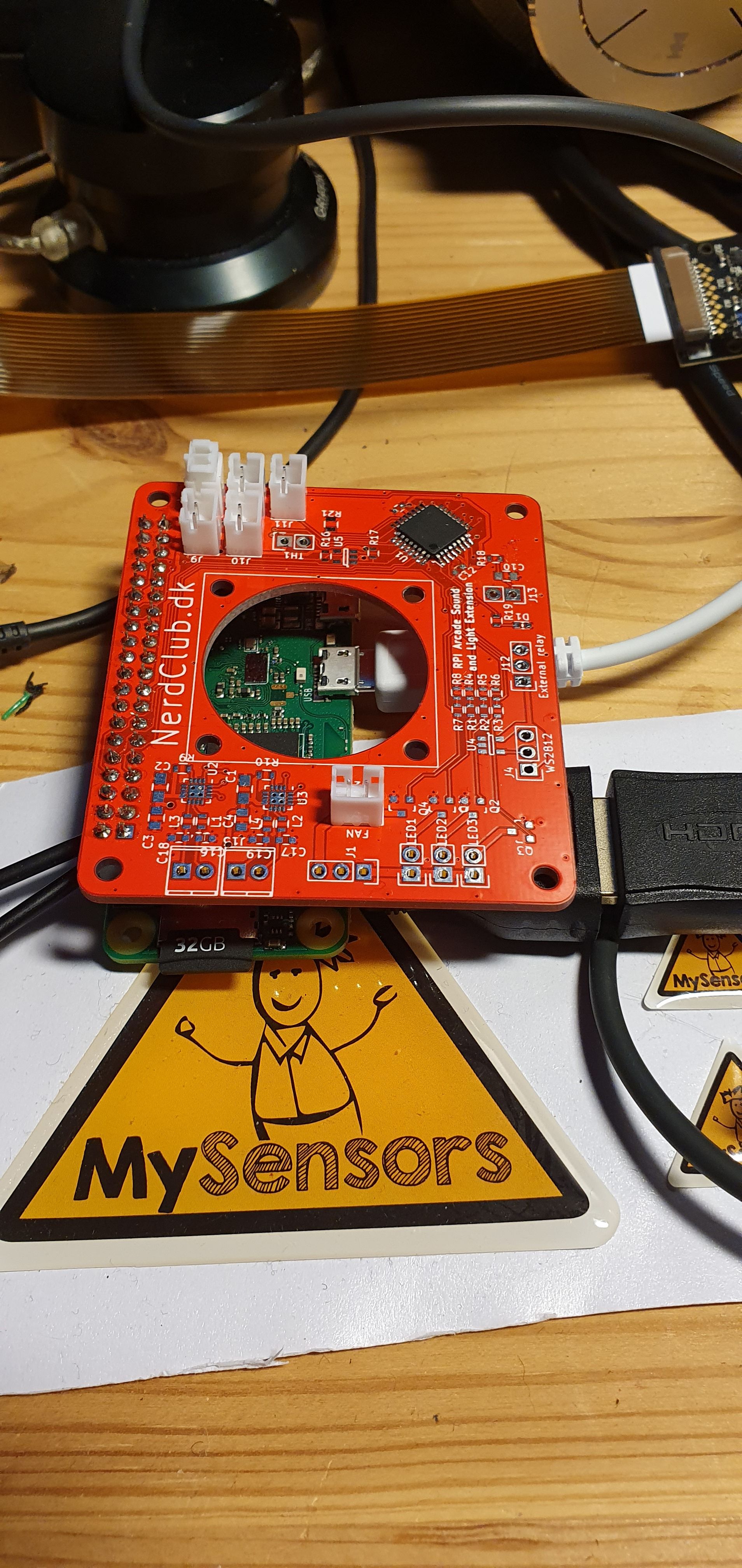
Features:
- stereo 3W class-d amplifier
- atmega328p
- 3 pwm channels for LED strips
- a port for WS2812 type led strips
- pwm channel for fan
- output for a relay to control mains input for the box (let the rpi shutdown cleanly, before disconnecting power)
- 5 button inputs (shared between rpi and atmega)
-
Hi, finished two nodes based on the same multi-purpose battery powered pcb (all the documentation here)
One is a door / window sensor based on a Reed switch.
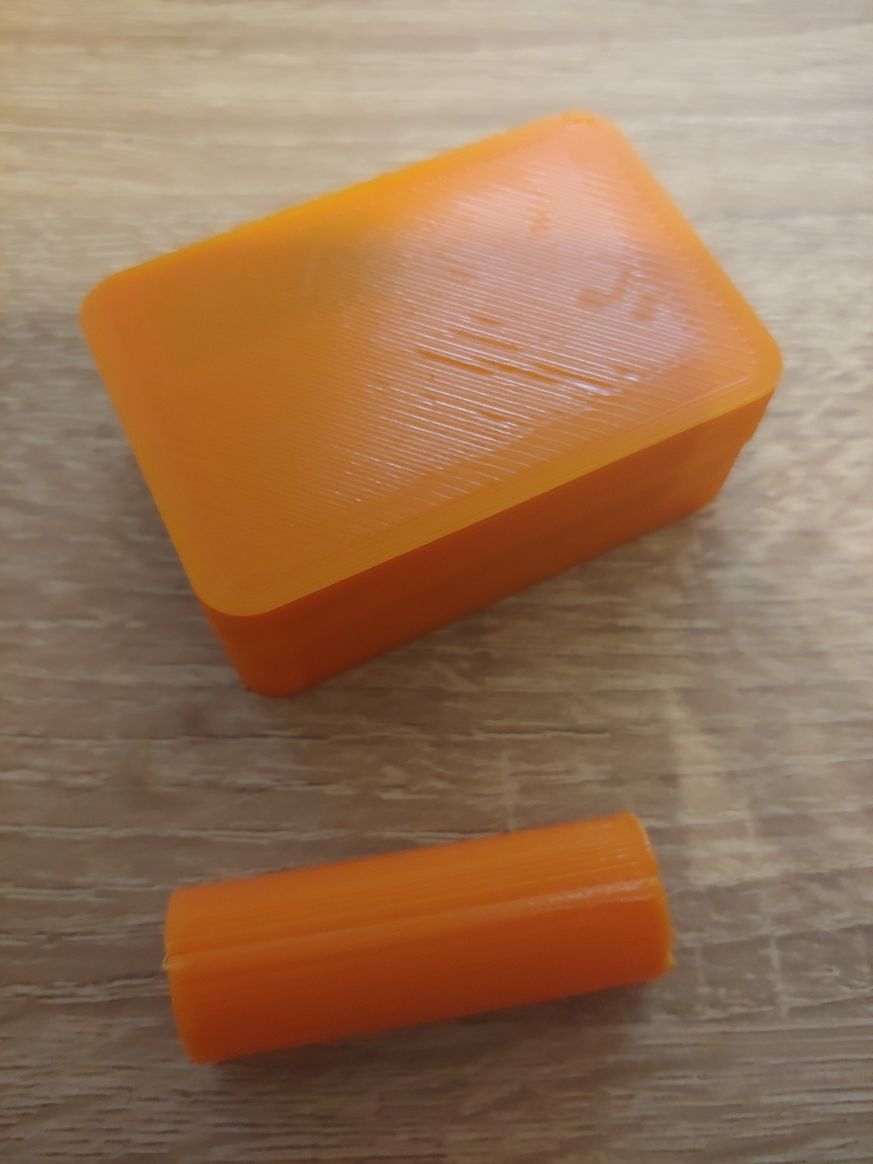
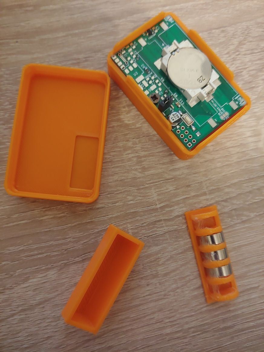
If someone is interested, the dedicated wiki page contains the detailed build instructions.
The other is a soil moisture sensor.
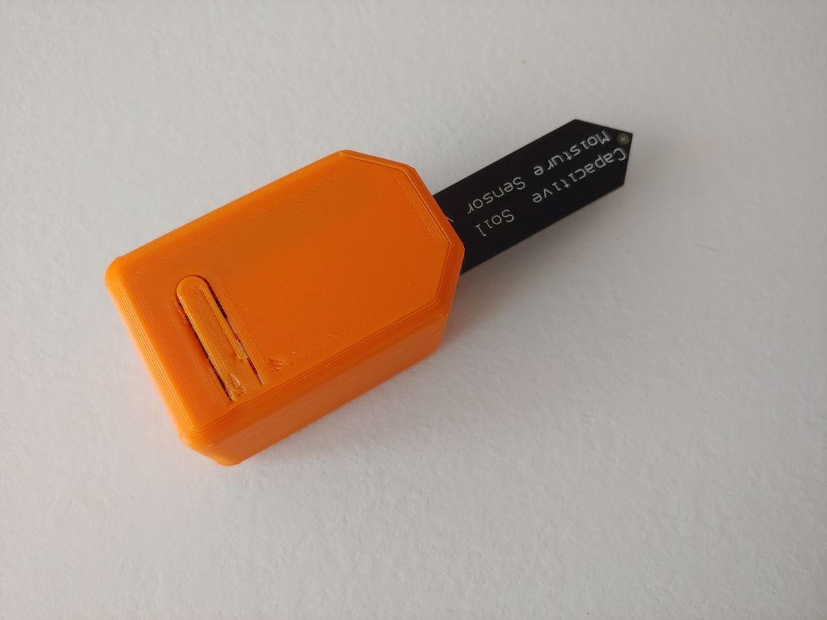
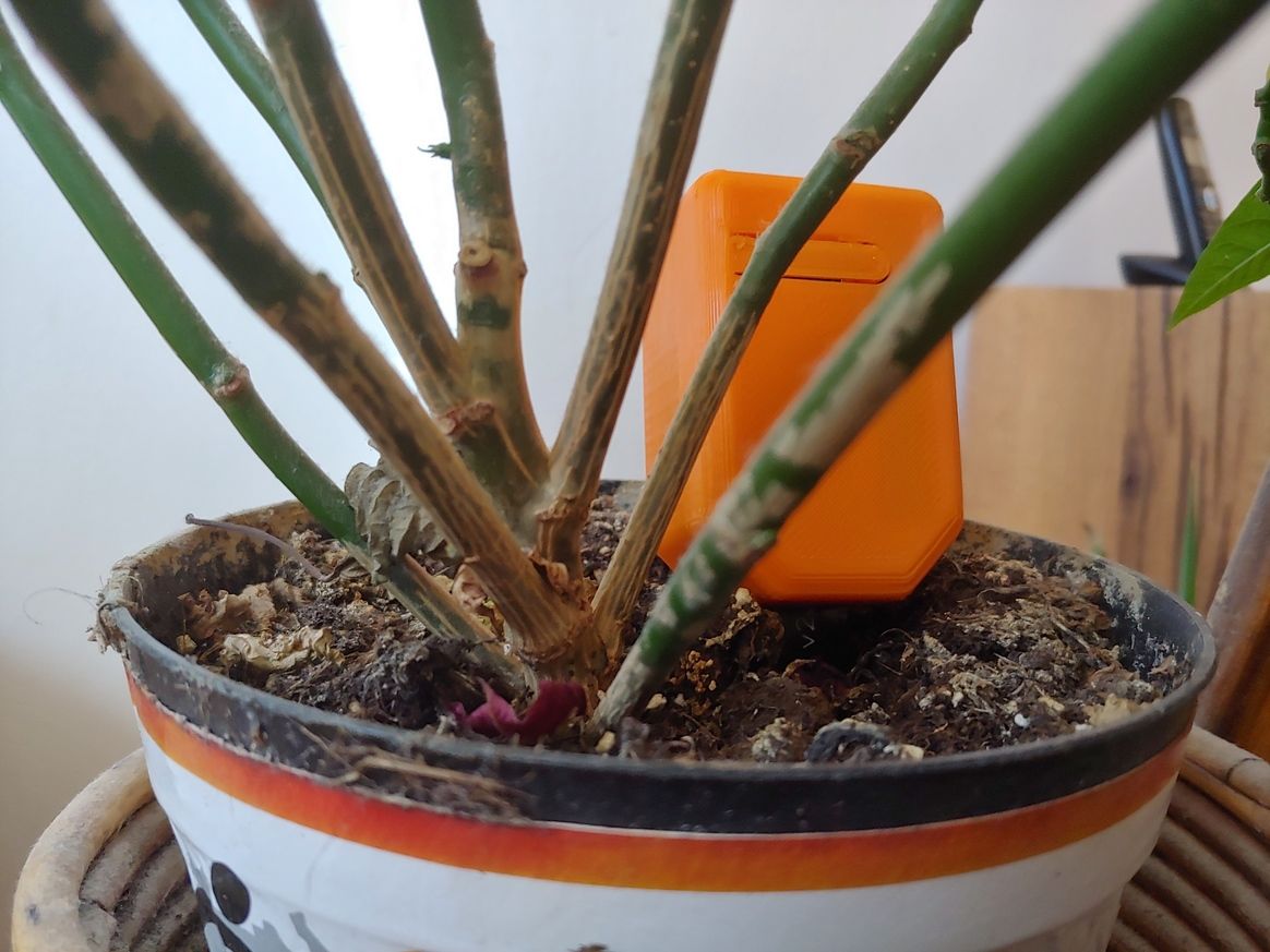
For this one, the wiki page is here.
Happy Easter, even if at home!
-
Anyone know or have experience with how well the underlying capacitive soil moisture sensors hold up over the long term? Clearly they're better than the cheap conductive electrode kind, which for most people don't last very long at all, but I recollect reading that water ultimately invades the PCB enough on even the capacitive designs that it goes kaput. Maybe they've been improved since then or maybe there are now known tricks for how to fortify them against that happening?
@NeverDie The guy with the swiss accent once said that you can coat the capacitive soil moisture sensors with a water resistant varnish or put it inside a waterproof shell.
https://www.youtube.com/watch?v=udmJyncDvw0
starting at ~7 mins.@franz-unix Ha, Great minds think alike. :D
-
@NeverDie The guy with the swiss accent once said that you can coat the capacitive soil moisture sensors with a water resistant varnish or put it inside a waterproof shell.
https://www.youtube.com/watch?v=udmJyncDvw0
starting at ~7 mins.@franz-unix Ha, Great minds think alike. :D
@BearWithBeard :+1: :grin: I love the video of the swiss guy!
-
@NeverDie The guy with the swiss accent once said that you can coat the capacitive soil moisture sensors with a water resistant varnish or put it inside a waterproof shell.
https://www.youtube.com/watch?v=udmJyncDvw0
starting at ~7 mins.@franz-unix Ha, Great minds think alike. :D
-
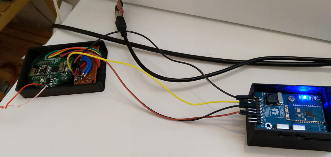
Today I have a very strange problem. I have created a new outdoor sensor which is powered by a 240v-5v HLK module. Its working VERY intermittent and should send data every 5 minutes (no exceptions).
Whats even more strange is that, when my outside node (called multi) is working, I have a battery powered node (sleep 15 min - send - sleep) that seems to go down, and the other way around (not always, but quite frequent - could be very unrelated but I have notised it a couple of times now).
Anyhow, Im very glad i build my logger node - works great once more. I use this so often and really recommend all with a bigger network to have some sort of mobile debugger. Most of the times I use the bluetooth module (2xAA powered) but at this point I have my node on my workbench powered by a USB adapter (orange wires). I then parasite power from the node to run the debugger and is now logging everything to a sd-card.
-
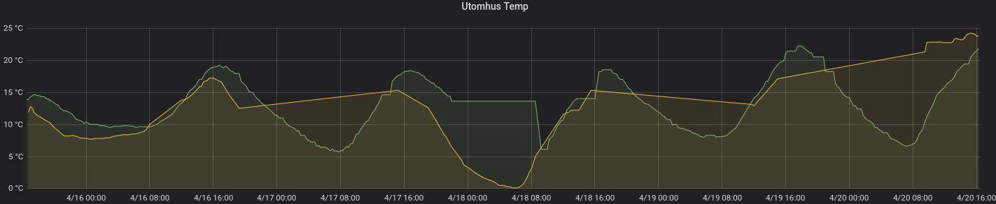
Another picture from today:
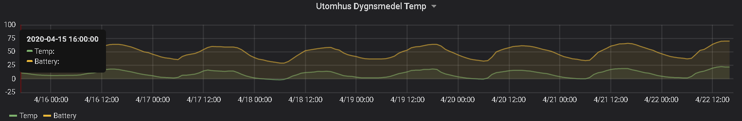
Just started working with coincells - CR2032 to be exact. Anyone knows why the battery % varies with the given temperature? Are those coincells very temp. dependent or I have made a misstake somewhere... ???
-
Another picture from today:
Just started working with coincells - CR2032 to be exact. Anyone knows why the battery % varies with the given temperature? Are those coincells very temp. dependent or I have made a misstake somewhere... ???
@sundberg84 said in What did you build today (Pictures) ?:
Anyone knows why the battery % varies with the given temperature
They don't like it when it's too cold. Check page 4 :
https://data.energizer.com/pdfs/lithiumcoin_appman.pdf
Hello! It looks like you're interested in this conversation, but you don't have an account yet.
Getting fed up of having to scroll through the same posts each visit? When you register for an account, you'll always come back to exactly where you were before, and choose to be notified of new replies (either via email, or push notification). You'll also be able to save bookmarks and upvote posts to show your appreciation to other community members.
With your input, this post could be even better 💗
Register Login