EasyPCB and RFM69 Issues
-
I am having some issues getting my sensors up and running and am looking for some advice.
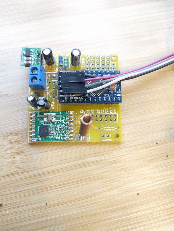
My setup is using RFM69 hardware @ 433mhz. The sensors are are using the EasyPCB circuit boards and the gateway is an D1 Wemos and a RFM69HW.
I know the gateway is functioning OK - I have tested communication between that and a sensor on a breadboard and they communicate fine. I did ponder if the frequencies could have been mismatched but the numbers on the chip for breadboard sensor and the 2 easypcb sensors I have made are identical so I would hope the same frequency.
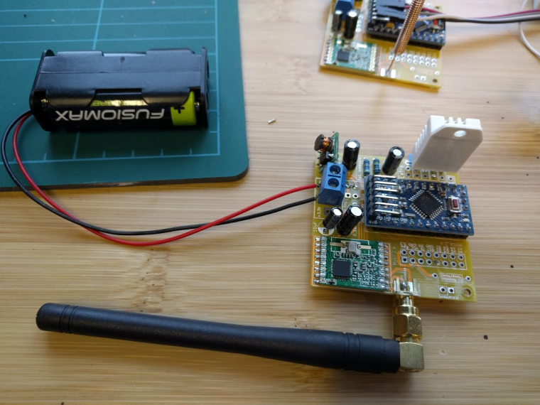
I have built 2 easyPCB sensors, Ive tried powering one from battery and one directly from the USB when debugging. The RFM69 has a strong 3.3v that doesnt seem to fluctuate or drop off atall.
Gateway Logs (Wemos Mini D1 - RFM69HW)
0;255;3;0;9;TSF:LRT:OK
0;255;3;0;9;TSM:INIT
0;255;3;0;9;TSF:WUR:MS=0
scandone
state: 0 -> 2 (b0)
state: 2 -> 3 (0)
state: 3 -> 5 (10)
add 0
aid 4
cnt

connected with Ryanmt, channel 10
dhcp client start...
0;255;3;0;9;TSM:INIT:TSP OK
0;255;3;0;9;TSM:INIT:GW MODE
0;255;3;0;9;TSM:READY:ID=0,PAR=0,DIS=0
0;255;3;0;9;MCO:REG:NOT NEEDED
f r0, scandone
.ip:192.168.5.17,mask:255.255.255.0,gw:192.168.5.1
.IP: 192.168.5.17
0;255;3;0;9;MCO:BGN:STP
0;255;3;0;9;MCO:BGN:INIT OK,TSP=1
pm open,type:2 0
Sensor Logs (EasyPCB - RFM69H - 3.3V Arduino Pro Mini)
0 MCO:BGN:INIT NODE,CP=RRNNA--,VER=2.1.1
4 TSM:INIT
4 TSF:WUR:MS=0
8 TSM:INIT:TSP OK
10 TSM:INIT:STATID=2
12 TSF:SID:OK,ID=2
14 TSM:FPAR
145 TSF:MSG:SEND,2-2-255-255,s=255,c=3,t=7,pt=0,l=0,sg=0,ft=0,st=OK:
2152 !TSM:FPAR:NO REPLY
2154 TSM:FPAR
2285 TSF:MSG:SEND,2-2-255-255,s=255,c=3,t=7,pt=0,l=0,sg=0,ft=0,st=OK:
4292 !TSM:FPAR:NO REPLY
4294 TSM:FPAR
4425 TSF:MSG:SEND,2-2-255-255,s=255,c=3,t=7,pt=0,l=0,sg=0,ft=0,st=OK:
6432 !TSM:FPAR:NO REPLY
6434 TSM:FPAR
6565 TSF:MSG:SEND,2-2-255-255,s=255,c=3,t=7,pt=0,l=0,sg=0,ft=0,st=OK:
8574 !TSM:FPAR:FAIL
8577 TSM:FAIL:CNT=1
8579 TSM:FAIL:PDT
The sketch is just the example battery sketch with the RFM69 module enabled and the node set to 2. I have built 2 identical nodes but both have this same issue of communicating to the gateway.
-
I am having some issues getting my sensors up and running and am looking for some advice.
My setup is using RFM69 hardware @ 433mhz. The sensors are are using the EasyPCB circuit boards and the gateway is an D1 Wemos and a RFM69HW.
I know the gateway is functioning OK - I have tested communication between that and a sensor on a breadboard and they communicate fine. I did ponder if the frequencies could have been mismatched but the numbers on the chip for breadboard sensor and the 2 easypcb sensors I have made are identical so I would hope the same frequency.
I have built 2 easyPCB sensors, Ive tried powering one from battery and one directly from the USB when debugging. The RFM69 has a strong 3.3v that doesnt seem to fluctuate or drop off atall.
Gateway Logs (Wemos Mini D1 - RFM69HW)
0;255;3;0;9;TSF:LRT:OK
0;255;3;0;9;TSM:INIT
0;255;3;0;9;TSF:WUR:MS=0
scandone
state: 0 -> 2 (b0)
state: 2 -> 3 (0)
state: 3 -> 5 (10)
add 0
aid 4
cnt

connected with Ryanmt, channel 10
dhcp client start...
0;255;3;0;9;TSM:INIT:TSP OK
0;255;3;0;9;TSM:INIT:GW MODE
0;255;3;0;9;TSM:READY:ID=0,PAR=0,DIS=0
0;255;3;0;9;MCO:REG:NOT NEEDED
f r0, scandone
.ip:192.168.5.17,mask:255.255.255.0,gw:192.168.5.1
.IP: 192.168.5.17
0;255;3;0;9;MCO:BGN:STP
0;255;3;0;9;MCO:BGN:INIT OK,TSP=1
pm open,type:2 0
Sensor Logs (EasyPCB - RFM69H - 3.3V Arduino Pro Mini)
0 MCO:BGN:INIT NODE,CP=RRNNA--,VER=2.1.1
4 TSM:INIT
4 TSF:WUR:MS=0
8 TSM:INIT:TSP OK
10 TSM:INIT:STATID=2
12 TSF:SID:OK,ID=2
14 TSM:FPAR
145 TSF:MSG:SEND,2-2-255-255,s=255,c=3,t=7,pt=0,l=0,sg=0,ft=0,st=OK:
2152 !TSM:FPAR:NO REPLY
2154 TSM:FPAR
2285 TSF:MSG:SEND,2-2-255-255,s=255,c=3,t=7,pt=0,l=0,sg=0,ft=0,st=OK:
4292 !TSM:FPAR:NO REPLY
4294 TSM:FPAR
4425 TSF:MSG:SEND,2-2-255-255,s=255,c=3,t=7,pt=0,l=0,sg=0,ft=0,st=OK:
6432 !TSM:FPAR:NO REPLY
6434 TSM:FPAR
6565 TSF:MSG:SEND,2-2-255-255,s=255,c=3,t=7,pt=0,l=0,sg=0,ft=0,st=OK:
8574 !TSM:FPAR:FAIL
8577 TSM:FAIL:CNT=1
8579 TSM:FAIL:PDT
The sketch is just the example battery sketch with the RFM69 module enabled and the node set to 2. I have built 2 identical nodes but both have this same issue of communicating to the gateway.
-
I'll try removing that then, they are especially cheap capacitor's..
The sma antenna is https://rover.ebay.com/rover/0/0/0?mpre=https%3A%2F%2Fwww.ebay.co.uk%2Fulk%2Fitm%2F171802359586
-
I'll try removing that then, they are especially cheap capacitor's..
The sma antenna is https://rover.ebay.com/rover/0/0/0?mpre=https%3A%2F%2Fwww.ebay.co.uk%2Fulk%2Fitm%2F171802359586
@Ryanmt hard to say exactly. Can you see any try/log in the gw when you get no reply in the node log?
As seen in the Nrf version that radio is very sensitive to noice and those boosters can be really crappy some times. I have working nodes with boosters but it's somewhat untested for me how sensitive rfm radios are. You could desolder the booster and wire Vin and Vout to rule the booster out.
-
I'll try removing that then, they are especially cheap capacitor's..
The sma antenna is https://rover.ebay.com/rover/0/0/0?mpre=https%3A%2F%2Fwww.ebay.co.uk%2Fulk%2Fitm%2F171802359586
@Ryanmt also in the first picture you power everything from the ftdi. I'm not sure that works so well. The pcb is designed to be powered from the power input.
-
@Ryanmt also in the first picture you power everything from the ftdi. I'm not sure that works so well. The pcb is designed to be powered from the power input.
@sundberg84 I did think that so have tried it both ways and neither work. Both get a steady 3.3v at transceiver
-
This post is deleted!
-
@Ryanmt also in the first picture you power everything from the ftdi. I'm not sure that works so well. The pcb is designed to be powered from the power input.
-
Ok then... good to know.
Let's continue... How about my questions above ? -
I'll try removing that then, they are especially cheap capacitor's..
The sma antenna is https://rover.ebay.com/rover/0/0/0?mpre=https%3A%2F%2Fwww.ebay.co.uk%2Fulk%2Fitm%2F171802359586
-
Thanks for the replies guys.
- The GW says nothing which to me indicates no TX from the sensors are reaching the gateway.
- I have powered from both FTDI and battery, my breadboard sensor works when powered from either FTDI or the battery + booster (same model)
Currently I can say the range for both SMA and the wound antenna is poor since neither work :-P My intention is for these to be long range as they will be at the bottom of the garden... when I get them up and running Ill try do some proper range tests and provide feedback if you are interested.
I sadly don’t own an oscilloscope, I would love to verify if the sensors are actually attempting to broadcast in anyway but I’m not sure I can do that with just a meter?
@Ryanmt - so, do I understand you correctly?
Exactly the same hardware/hardware-setup (incl antenna) & software works on the breadboard with that gateway - but when you solder them to the PCB it stops working?If so there are these options:
- You have made some soldering mistake (created a short.) (The solder-job looks really good on the images though...)
- The PCB you are using has some sort of manufacturing error.
- The antenna (length) needs to be changed on the PCB vs the breadboard setup.
I would set my multimeter into continuity and measure all lines, ie from radio -> mcu. Also measure continuity between all solder points next to each other on the radio(to make sure you dont have any shorts). Next thing would be to test different length on the antenna. You can also compare the PCB traces to the images on openhardware.io
The sketch is just the example battery sketch with the RFM69 module enabled
Could you also post the sketch you are using? (The standard sketch does not include the H def but i guess you added that)
Hello! It looks like you're interested in this conversation, but you don't have an account yet.
Getting fed up of having to scroll through the same posts each visit? When you register for an account, you'll always come back to exactly where you were before, and choose to be notified of new replies (either via email, or push notification). You'll also be able to save bookmarks and upvote posts to show your appreciation to other community members.
With your input, this post could be even better 💗
Register Login