CNC PCB milling
-
@NeverDie
too bad! perhaps it's just power supply regulator or a fet which died?? or maybe one of the drivers, just ideas.. I don't know this board.
Saying this because that was the first things I checked on my 3d printer Ramps board- changed ldo (on arduino mega) because I didn't trust clones..
- a few fets for better rdson (on the Ramps board). then there was no more heat..
- and of course I calibrated the steppers drivers
Edit: argh, i misread it's non responsive..then mcu maybe.
@scalz said in CNC PCB milling:
@NeverDie
too bad! perhaps it's just power supply regulator or a fet which died?? or maybe one of the drivers, just ideas.. I don't know this board.
Saying this because that was the first things I checked on my 3d printer Ramps board- changed ldo (on arduino mega) because I didn't trust clones..
- a few fets for better rdson (on the Ramps board). then there was no more heat..
- and of course I calibrated the steppers drivers
Edit: argh, i misread it's non responsive..then mcu maybe.
It's receiving power, because the red LED lights up when I connect to it. The atmega328p also appears to be receiving the characters I send to it, because there's an LED that lights very briefly when I do that. However, I'm not seeing that it is sending any characters back, and I'm guessing there would be yet another LED which would indicate that if there were. So, I'm guessing most likely the mcu is dead. I wouldn't be surprised if it got some kind of electrostatic shock when probing, since the probing circuit appears to be wired directly to one of its pins. Also, I was attaching the probe immediately prior to its dying. That makes it a prime suspect in my mind. I don't want to over-react, but for the future I may try isolating that circuit with an opto-isolator or similar to hopefully prevent a recurrence. On the face of it, the present design seems like a heartache just waiting to happen.
-
@neverdie or you could just mill your own board since now you have the tools :ok_hand:
@executivul said in CNC PCB milling:
@neverdie or you could just mill your own board since now you have the tools :ok_hand:
Not if it's broke he doesn't.
-
That's the original designer of that shield :
-
@scalz said in CNC PCB milling:
@NeverDie
too bad! perhaps it's just power supply regulator or a fet which died?? or maybe one of the drivers, just ideas.. I don't know this board.
Saying this because that was the first things I checked on my 3d printer Ramps board- changed ldo (on arduino mega) because I didn't trust clones..
- a few fets for better rdson (on the Ramps board). then there was no more heat..
- and of course I calibrated the steppers drivers
Edit: argh, i misread it's non responsive..then mcu maybe.
It's receiving power, because the red LED lights up when I connect to it. The atmega328p also appears to be receiving the characters I send to it, because there's an LED that lights very briefly when I do that. However, I'm not seeing that it is sending any characters back, and I'm guessing there would be yet another LED which would indicate that if there were. So, I'm guessing most likely the mcu is dead. I wouldn't be surprised if it got some kind of electrostatic shock when probing, since the probing circuit appears to be wired directly to one of its pins. Also, I was attaching the probe immediately prior to its dying. That makes it a prime suspect in my mind. I don't want to over-react, but for the future I may try isolating that circuit with an opto-isolator or similar to hopefully prevent a recurrence. On the face of it, the present design seems like a heartache just waiting to happen.
@neverdie interesting.
the LEDs are driven by the communication line itself, so if you send a character on serial to the board, then basically your data will flash the MCU's RX LED, not the MCU.there should be no problem at all with the touch probe solution/circuit. it equals to a simple button sensing on a common arduino's pin, it cannot cause the MCU's death, if you are connecting everything properly.
-
Once I find my dragon, I'll burn a new atmega328p with the grbl 1.1 and replace the suspect atmega328p. Hopefully it will work then. If not, then I'm guessing it's the the usb-to-serial chip gone bad. Anyhow, one way or another I'll get to the bottom of it. And if I don't, a replacement board is on its way.
-
@neverdie don't stick to you missing dragon programmer. use an arduino as an isp programmer instead. also, if you burn the bootloader, next time you can use the usb connector for update.
-
I extracted the atmega328p chip that was on the woodpecker and attempted to read it. Fail. Normal voltage is 5v on a fresh chip, but it was reading only 4.8v. Also, it got quite hot. So, I think it is defective.
-
I've established that the GRBL1.1f firmware assumes it's running at 16Mhz. So, I guess I'll try the following fuse settings, typically used on a 16Mhz Pro Mini:
pro5v328.bootloader.low_fuses=0xFF  <<< same as 8 MHz
pro5v328.bootloader.high_fuses=0xDA <<< same as 8 MHz
pro5v328.bootloader.extended_fuses=0x05 <<< same as 8 MHz
BODLEVEL = 2V7 RSTDISBL = [ ] DWEN = [ ] SPIEN = [X] WDTON = [ ] EESAVE = [ ] BOOTSZ = 1024W_3C00 BOOTRST = [X] CKDIV8 = [ ] CKOUT = [ ] SUT_CKSEL = EXTXOSC_8MHZ_XX_16KCK_14CK_65MS EXTENDED = 0x05 (valid) HIGH = 0xDA (valid) LOW = 0xFF (valid) -
I soldered in the replacement atmega328p, after burning its firmware with GRBL 1.1f, and Bingo! That fixed it:
Grbl 1.1f ['$' for help]Because of the upgraded firmware, I'm actually better off now than I was before. :)
-
@neverdie I still use my default settings (see below). I re-applied these settings after I flashed the board to grbl 1.1f.
to be honest, after I found the right parameters for the PCB milling jobs I did not went further to fine tune the CNC settings, due to the lack of time. maybe later of the year, but currently I'm more than happy with the results.$0=10 (step pulse, usec) $1=25 (step idle delay, msec) $2=0 (step port invert mask:00000000) $3=5 (dir port invert mask:00000101) $4=0 (step enable invert, bool) $5=0 (limit pins invert, bool) $6=0 (probe pin invert, bool) $10=3 (status report mask:00000011) $11=0.010 (junction deviation, mm) $12=0.002 (arc tolerance, mm) $13=0 (report inches, bool) $20=0 (soft limits, bool) $21=0 (hard limits, bool) $22=0 (homing cycle, bool) $23=0 (homing dir invert mask:00000000) $24=25.000 (homing feed, mm/min) $25=500.000 (homing seek, mm/min) $26=250 (homing debounce, msec) $27=1.000 (homing pull-off, mm) $100=800.000 (x, step/mm) $101=800.000 (y, step/mm) $102=800.000 (z, step/mm) $110=800.000 (x max rate, mm/min) $111=800.000 (y max rate, mm/min) $112=500.000 (z max rate, mm/min) $120=10.000 (x accel, mm/sec^2) $121=10.000 (y accel, mm/sec^2) $122=10.000 (z accel, mm/sec^2) $130=200.000 (x max travel, mm) $131=200.000 (y max travel, mm) $132=200.000 (z max travel, mm)```@andrew said in CNC PCB milling:
@neverdie I still use my default settings (see below). I re-applied these settings after I flashed the board to grbl 1.1f.
to be honest, after I found the right parameters for the PCB milling jobs I did not went further to fine tune the CNC settings, due to the lack of time. maybe later of the year, but currently I'm more than happy with the results.$0=10 (step pulse, usec) $1=25 (step idle delay, msec) $2=0 (step port invert mask:00000000) $3=5 (dir port invert mask:00000101) $4=0 (step enable invert, bool) $5=0 (limit pins invert, bool) $6=0 (probe pin invert, bool) $10=3 (status report mask:00000011) $11=0.010 (junction deviation, mm) $12=0.002 (arc tolerance, mm) $13=0 (report inches, bool) $20=0 (soft limits, bool) $21=0 (hard limits, bool) $22=0 (homing cycle, bool) $23=0 (homing dir invert mask:00000000) $24=25.000 (homing feed, mm/min) $25=500.000 (homing seek, mm/min) $26=250 (homing debounce, msec) $27=1.000 (homing pull-off, mm) $100=800.000 (x, step/mm) $101=800.000 (y, step/mm) $102=800.000 (z, step/mm) $110=800.000 (x max rate, mm/min) $111=800.000 (y max rate, mm/min) $112=500.000 (z max rate, mm/min) $120=10.000 (x accel, mm/sec^2) $121=10.000 (y accel, mm/sec^2) $122=10.000 (z accel, mm/sec^2) $130=200.000 (x max travel, mm) $131=200.000 (y max travel, mm) $132=200.000 (z max travel, mm)```Looks as though GRBL1.1f has exposed some additional registers than GRBL0.9 did:
$0=10
$1=25
$2=0
$3=5
$4=0
$5=0
$6=0
$10=3
$11=0.010
$12=0.002
$13=0
$20=0
$21=0
$22=0
$23=0
$24=25.000
$25=500.000
$26=250
$27=1.000
$30=1000
$31=0
$32=0
$100=800.000
$101=800.000
$102=800.000
$110=800.000
$111=800.000
$112=500.000
$120=10.000
$121=10.000
$122=10.000
$130=200.000
$131=200.000
$132=200.000
namely, registers 30, 31, and 32. Not sure what their values should be, or if it even matters.
Interestingly, the stepper motors have a distinctly different sound to them when running Chilipeppr with GRBL1.1f (as contrasted with GRBL0.9).
-
I am having a serious problem, though, which is that no matter whether I use Chilipeppr to jog the x-axis to the left or to the right, it always veers to the left. It never goes to the right. Y and Z seem to be working OK however.
-
I am having a serious problem, though, which is that no matter whether I use Chilipeppr to jog the x-axis to the left or to the right, it always veers to the left. It never goes to the right. Y and Z seem to be working OK however.
-
@andrew said in CNC PCB milling:
@neverdie I still use my default settings (see below). I re-applied these settings after I flashed the board to grbl 1.1f.
to be honest, after I found the right parameters for the PCB milling jobs I did not went further to fine tune the CNC settings, due to the lack of time. maybe later of the year, but currently I'm more than happy with the results.$0=10 (step pulse, usec) $1=25 (step idle delay, msec) $2=0 (step port invert mask:00000000) $3=5 (dir port invert mask:00000101) $4=0 (step enable invert, bool) $5=0 (limit pins invert, bool) $6=0 (probe pin invert, bool) $10=3 (status report mask:00000011) $11=0.010 (junction deviation, mm) $12=0.002 (arc tolerance, mm) $13=0 (report inches, bool) $20=0 (soft limits, bool) $21=0 (hard limits, bool) $22=0 (homing cycle, bool) $23=0 (homing dir invert mask:00000000) $24=25.000 (homing feed, mm/min) $25=500.000 (homing seek, mm/min) $26=250 (homing debounce, msec) $27=1.000 (homing pull-off, mm) $100=800.000 (x, step/mm) $101=800.000 (y, step/mm) $102=800.000 (z, step/mm) $110=800.000 (x max rate, mm/min) $111=800.000 (y max rate, mm/min) $112=500.000 (z max rate, mm/min) $120=10.000 (x accel, mm/sec^2) $121=10.000 (y accel, mm/sec^2) $122=10.000 (z accel, mm/sec^2) $130=200.000 (x max travel, mm) $131=200.000 (y max travel, mm) $132=200.000 (z max travel, mm)```Looks as though GRBL1.1f has exposed some additional registers than GRBL0.9 did:
$0=10
$1=25
$2=0
$3=5
$4=0
$5=0
$6=0
$10=3
$11=0.010
$12=0.002
$13=0
$20=0
$21=0
$22=0
$23=0
$24=25.000
$25=500.000
$26=250
$27=1.000
$30=1000
$31=0
$32=0
$100=800.000
$101=800.000
$102=800.000
$110=800.000
$111=800.000
$112=500.000
$120=10.000
$121=10.000
$122=10.000
$130=200.000
$131=200.000
$132=200.000
namely, registers 30, 31, and 32. Not sure what their values should be, or if it even matters.
Interestingly, the stepper motors have a distinctly different sound to them when running Chilipeppr with GRBL1.1f (as contrasted with GRBL0.9).
@neverdie said in CNC PCB milling:
namely, registers 30, 31, and 32. Not sure what their values should be, or if it even matters.
I found out what they mean:
$30=1000. Max spindle speed, RPM $31=0. Min spindle speed, RPM $32=0 Laser mode, boolean -
@neverdie
Is it working correctly if you just issue a G0 x10 then x-10?
did you switch to the jpadie workspace for v1.1?
sounds like you have a short on pin 5@rmtucker said in CNC PCB milling:
Is it working correctly if you just issue a G0 x10 then x-10?
No, it goes left in both instances.
@rmtucker said in CNC PCB milling:
did you switch to the jpadie workspace for v1.1?
yes
-
@rmtucker said in CNC PCB milling:
Is it working correctly if you just issue a G0 x10 then x-10?
No, it goes left in both instances.
@rmtucker said in CNC PCB milling:
did you switch to the jpadie workspace for v1.1?
yes
@neverdie sorry, I'm abroad, with very limited availability, so cannot answer too quickly.
based on the mentioned facts it seems to me, that the X axis direction pin is sticked to one position, maybe it has a solder bridge to another pin, or vcc / gnd directly.

-
@neverdie sorry, I'm abroad, with very limited availability, so cannot answer too quickly.
based on the mentioned facts it seems to me, that the X axis direction pin is sticked to one position, maybe it has a solder bridge to another pin, or vcc / gnd directly.
@andrew said in CNC PCB milling:
@neverdie sorry, I'm abroad, with very limited availability, so cannot answer too quickly.
based on the mentioned facts it seems to me, that the X axis direction pin is sticked to one position, maybe it has a solder bridge to another pin, or vcc / gnd directly.
Thanks! You nailed it. It turns out the solder connection on the atmega328p pin corresponding to D5 just wasn't good enough. I resoldered it, and now the X-axis works in both directions. :)
-
I'm receiving this error message now:

However, it's not obvious how to delete the files it's referring to. Anyone know how? -
Great news! Grbl1.1f makes all the difference. I tried milling at 6 mil separation using the upgraded grbl1.1f, and it works!
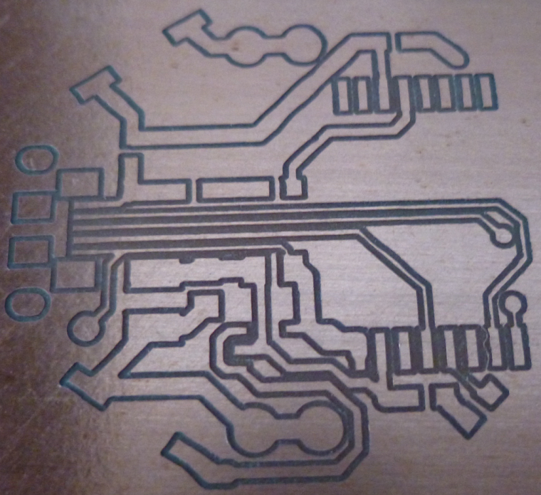
There's a huge difference between being able to evolve a single PCB design to perfect it rather than having to work on a "dumbed down" design (for a CNC or some other DIY etching process) before being able to get "the real deal" from a PCB fabricator. So, I'm very relieved that the first option now seems possible. :)