Build a reliable power supply chain
-
Hi guys,
I'm writing this not because I have a problem but because I was finally able to solve some. I think it's worthwhile posting my experience here to maybe help some of you.For a long time I was experiencing random unreliable radio communications with NRF24L01+ nodes powered by power adaptors. Some of my nodes worked perfectly while some others were receiving data really inreliably and generally had problems communicating. After a lot of try and error and reading some tips I think I have now found a reliable solution: Power supply input filtering.
I knew for a long time that the transceivers we use are highly sensitive to the cleanliness of their power supply and that typical cheap AC / DC switching power supplies (like e.g. a 5V phone charger) produces pretty noisy DC. But due to lack of an oscilloscope I didn't really know what to do about that.
After I've read this awesome post I tried putting such a recommended LC filter between the output of my LDO and the transceiver to clean out the power supplied to the transceiver. Unfortunately it didn't really work and I still had the same problems. After a lot of trying and playing around I have developed the theory that some linear power regulators are very pedantic about their output capacitors (specifically their respective ESR values) and you have to be really careful about what to put on the output of those things. I also learned that LC filter design is not as trivial as I thought: In bad case scenarios such a filter can start to oscillate and make things worse. So if you don't really know what you're doing and don't have an oscilloscope it is difficult to accurately design a working filter.
So my proposed solution is the following: Put such an LC filter directly between the output of your AC/DC power brick and the input of the power regulator. Linear LDO regulators typically already output pretty clean DC voltage, but only if their input is also kinda clean. The parameter that describes this correlation is called the "PSRR" or "power supply ripple rejection". In other words: shit in --> little less shit out.
By putting an LC filter (or Pi filter, whaterver) in front of the power regulator you are pre-filtering most of the bad output ripple of the cheap AliExpress 5V phone chargers and other power bricks. This "kinda clean" voltage is then supplied to the LDO which can do the rest of the work and filter out the remaining ripple or oscillation.
I don't know if my description is absolutely accurate and if it is the best solution that also a professional electronics design engineer would choose but at least for me it was the first thing that really worked.
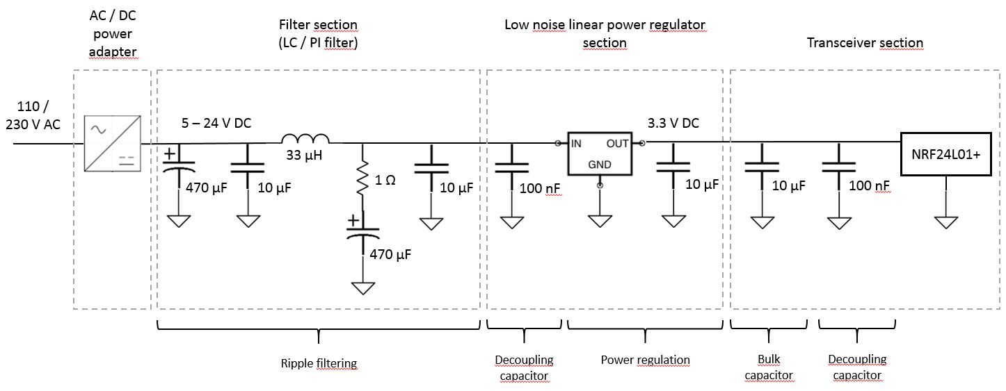
In the end my proposed "optimal" (in respect to complexity vs. benefit) power chain can look like this:
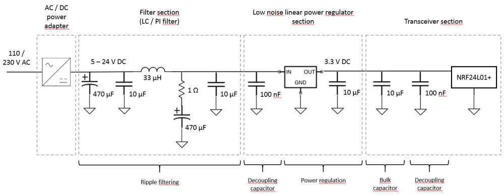
I don't know if the capacitor and inductor sizes are optimal, but something approximately to this is running flawlessly in my home on several nodes. As an LDO I have been successful with the MIC5205 (same as Arduino Pro Mini), AMS1117, MCP1700, LE33 and LP2950 (this was the one I initially had the most problems with).
Also if you want to use such a design, keep the components of the individual sections as close as possible together. Between the blocks you can (within reason) do what you want, but you will get the highest quality out of short distances within the sections.
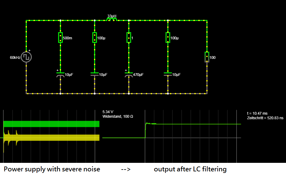
edit: I played around with different filter values in circuitjs and updated some things in the proposed circuit diagram. I decreased the inductor size from 333uF to 33uF (Low-pass cutoff frequency is higher but should be sufficient for AC adapters with a switching frequency higher than ~60kHz) and roughly doubled the size of the LC filter capacitor. Also I implemented a damping resistor (1 ohm resistor in series with 470uF capacitor) to optimize the behavior. Here you can see the result:
-
what i have and it is working so far but not for W5100 gateway.
5v--10uF----1uF----(1117 3.3v)----10uf----1uf---->3.3v for nRFhave you tried your schematic for W5100 gateway? i m having some issues with W5100 waiting for some parts to get delivered. another 3 weeks to go ....
-
what i have and it is working so far but not for W5100 gateway.
5v--10uF----1uF----(1117 3.3v)----10uf----1uf---->3.3v for nRFhave you tried your schematic for W5100 gateway? i m having some issues with W5100 waiting for some parts to get delivered. another 3 weeks to go ....
@pihome said in Build a reliable power supply chain:
what i have and it is working so far but not for W5100 gateway.
5v--10uF----1uF----(1117 3.3v)----10uf----1uf---->3.3v for nRFhave you tried your schematic for W5100 gateway? i m having some issues with W5100 waiting for some parts to get delivered. another 3 weeks to go ....
Hi pihome,
I am successfully running a W5100 gateway with an AMS1117 for the Transceiver and rarely have problems with it. But on my gateway I have an NRF24L01+/PA Transceiver, so the larger version with amplifier and external antenna.
What I have learned about the large module:- You have to shield it. When I was using it without shielding I had a lot of communication problems. In my experience, shielding doesn't make such a difference on the smaller versions of the transceivers, but on the large ones it does.
- It is less sensitive to power supply ripple than the smaller modules, but need more power. I assume this comes from the inherently higher receiving sensitivity due to the signal amplifier.
Therefore it would be interesting to know which transceiver version you are using. If you are also using the large transceiver with amplifier and external antenna, I would first advice to shield it. If you are using the standard module without external antenna I could imagine that our power adapter has a high output ripple that the AMS1117 is partly outputting to the NRF24L01+. In this case my proposed filter design could help with your problems.
After my findings with the LC filter connected to the input of the LDO, I also upgraded my described gateway configuration with this circuit. I can't say if it improved its performance because it was already working quite well, but it also didn't degrade it. Therefore I would suggest that you try it out and report back if it could solve your problem.
edit: What also came to mind is your actual power adapter. How much current can it provide? I know that the W5100 Ethernet module is consuming a relatively high amount of power as it gets warm when it's powered. It also has an on board AMS1117 regulator which can supply 800mA. If you are using a small 500mA power supply or something like this maybe your power adapter is too small.
-
Thanks @Mathea90 for bringing up this interesting subject.
It's sure difficult I believe to find a power supply for various Arduino projects that's both reliable and has a low cost.
@sundberg84 made a nice breakout PCB for the HLK-PM01, that "was considered at that time (2015-2017) the best AC to DC 5v module option (within reasonable price range)."
I hesitate though to build them due to that they will not be certified and if I cause a fire at my home, my home insurance may not cover the damages that can arise. With that being said, I'm quite sure that the HLK-PM01-breakout-board is by far much more safer than many wall plug chargers marked with CE (China Export).
It would be nice to have a breakout board that can turn the power from any random 5V wall plug charger into something that's clean and ripple free with a good margin to feed NRF24L01+ nodes with. With such a board I wouldn't have to be involved in working directly with 230V AC.
Meanwhile I'll probably try to build me a couple of LC filters using prototype breadboards.
Thanks again and keep up the good work!
@รอเร-อ Yeah, maybe it would be a nice project to design such a breakout board. Currently I'm all tied up in designing completely integrated custom PCBs. So the filter is sharing the same board as the Atmega328, the NRF24L01, as well as whatever specific components are needed.
Most of the time I see those NRF24L01 power breakout boards getting recommended. I have never used them but in the end it's just an AMS1117 power regulator with input and output capacitors. I can imagine them working fine when using a high quality 5V power supply, but it will have the same problems if you have ripple and general noise on your power supply.
-
@mathea90 Out of curiosity: how do you feel about these boards?
https://www.aliexpress.com/af/nano-wireless-expansion.html
I love them. Just plug in the NRF24 and you're done. Lots of VCC and GND lines for all the sensors.
They also seem to have a lot of those 1117 parts?
-
@mathea90 Out of curiosity: how do you feel about these boards?
https://www.aliexpress.com/af/nano-wireless-expansion.html
I love them. Just plug in the NRF24 and you're done. Lots of VCC and GND lines for all the sensors.
They also seem to have a lot of those 1117 parts?
@alowhum looks interesting. In case of the power supply for the NRF24L01+ they are the same as the small breakout boards: 1117 regulator. But it looks like there is another regulator for the 5V supply of the rest of the board. I assume that the 3.3V regulator is hooked up to the 5V output of the other one. So you have two regulators in series, which gives you a very good ripple rejection of the input supply. I assume they will work quite nicely.
-
Hi guys,
I'm writing this not because I have a problem but because I was finally able to solve some. I think it's worthwhile posting my experience here to maybe help some of you.For a long time I was experiencing random unreliable radio communications with NRF24L01+ nodes powered by power adaptors. Some of my nodes worked perfectly while some others were receiving data really inreliably and generally had problems communicating. After a lot of try and error and reading some tips I think I have now found a reliable solution: Power supply input filtering.
I knew for a long time that the transceivers we use are highly sensitive to the cleanliness of their power supply and that typical cheap AC / DC switching power supplies (like e.g. a 5V phone charger) produces pretty noisy DC. But due to lack of an oscilloscope I didn't really know what to do about that.
After I've read this awesome post I tried putting such a recommended LC filter between the output of my LDO and the transceiver to clean out the power supplied to the transceiver. Unfortunately it didn't really work and I still had the same problems. After a lot of trying and playing around I have developed the theory that some linear power regulators are very pedantic about their output capacitors (specifically their respective ESR values) and you have to be really careful about what to put on the output of those things. I also learned that LC filter design is not as trivial as I thought: In bad case scenarios such a filter can start to oscillate and make things worse. So if you don't really know what you're doing and don't have an oscilloscope it is difficult to accurately design a working filter.
So my proposed solution is the following: Put such an LC filter directly between the output of your AC/DC power brick and the input of the power regulator. Linear LDO regulators typically already output pretty clean DC voltage, but only if their input is also kinda clean. The parameter that describes this correlation is called the "PSRR" or "power supply ripple rejection". In other words: shit in --> little less shit out.
By putting an LC filter (or Pi filter, whaterver) in front of the power regulator you are pre-filtering most of the bad output ripple of the cheap AliExpress 5V phone chargers and other power bricks. This "kinda clean" voltage is then supplied to the LDO which can do the rest of the work and filter out the remaining ripple or oscillation.
I don't know if my description is absolutely accurate and if it is the best solution that also a professional electronics design engineer would choose but at least for me it was the first thing that really worked.
In the end my proposed "optimal" (in respect to complexity vs. benefit) power chain can look like this:
I don't know if the capacitor and inductor sizes are optimal, but something approximately to this is running flawlessly in my home on several nodes. As an LDO I have been successful with the MIC5205 (same as Arduino Pro Mini), AMS1117, MCP1700, LE33 and LP2950 (this was the one I initially had the most problems with).
Also if you want to use such a design, keep the components of the individual sections as close as possible together. Between the blocks you can (within reason) do what you want, but you will get the highest quality out of short distances within the sections.
edit: I played around with different filter values in circuitjs and updated some things in the proposed circuit diagram. I decreased the inductor size from 333uF to 33uF (Low-pass cutoff frequency is higher but should be sufficient for AC adapters with a switching frequency higher than ~60kHz) and roughly doubled the size of the LC filter capacitor. Also I implemented a damping resistor (1 ohm resistor in series with 470uF capacitor) to optimize the behavior. Here you can see the result:
@mathea90 What kind of capacitors are you using? Something i just recently learned: the kind of capacitor--not just its value---can make a difference:https://www.youtube.com/watch?v=WytU5uj78-4
According to the video, you should aspire to use ceramic capacitors.
-
@mathea90 What kind of capacitors are you using? Something i just recently learned: the kind of capacitor--not just its value---can make a difference:https://www.youtube.com/watch?v=WytU5uj78-4
According to the video, you should aspire to use ceramic capacitors.
@neverdie - I have had boosters on my EasyPCB not working with electrolytic capacitors but switching to a ceramic makes the radio come alive - so I have a real-world example of this. In the same time, I guess the frequency is really important before choosing.
-
The other thing to maybe look at would be the type of inductor used in the OP's diagram. I know from working on the solar power boost converters that not all inductors with the same inductance value behave the same either. In addition, layout can have a big effect as well. In general, you want the parts very close together, and so surface mount parts is the preferred way to go.
I like what the OP has posted so far. It would be great to have a well scrubbed reference design for power supply filtering, with part numbers and probably layout guidance, that we could then just wack into whatever it is that we build with the confidence that we then have guaranteed clean power. Unlike the OP, I do have an oscilliscope, so I would be happy to do testing and post the results if there's first some consensus as to the design.
-
Looking on Digikey, I see only two LDO's that are self described as ultra-low noise. The one by TI is the more affordable of the two:
https://www.digikey.com/product-detail/en/texas-instruments/LP5907MFX-3.3-NOPB/296-38557-1-ND/5034443So, I guess, why not? Might as well use that in the future.
-
Looks to be the same as: http://www.readytoflyquads.com/rtf-lc-filter-3amp-2-4s
I'm curious as to what, in addition to being an LC filter, this filter does. It has quite a few components.
-
@pihome said in Build a reliable power supply chain:
what i have and it is working so far but not for W5100 gateway.
5v--10uF----1uF----(1117 3.3v)----10uf----1uf---->3.3v for nRFhave you tried your schematic for W5100 gateway? i m having some issues with W5100 waiting for some parts to get delivered. another 3 weeks to go ....
Hi pihome,
I am successfully running a W5100 gateway with an AMS1117 for the Transceiver and rarely have problems with it. But on my gateway I have an NRF24L01+/PA Transceiver, so the larger version with amplifier and external antenna.
What I have learned about the large module:- You have to shield it. When I was using it without shielding I had a lot of communication problems. In my experience, shielding doesn't make such a difference on the smaller versions of the transceivers, but on the large ones it does.
- It is less sensitive to power supply ripple than the smaller modules, but need more power. I assume this comes from the inherently higher receiving sensitivity due to the signal amplifier.
Therefore it would be interesting to know which transceiver version you are using. If you are also using the large transceiver with amplifier and external antenna, I would first advice to shield it. If you are using the standard module without external antenna I could imagine that our power adapter has a high output ripple that the AMS1117 is partly outputting to the NRF24L01+. In this case my proposed filter design could help with your problems.
After my findings with the LC filter connected to the input of the LDO, I also upgraded my described gateway configuration with this circuit. I can't say if it improved its performance because it was already working quite well, but it also didn't degrade it. Therefore I would suggest that you try it out and report back if it could solve your problem.
edit: What also came to mind is your actual power adapter. How much current can it provide? I know that the W5100 Ethernet module is consuming a relatively high amount of power as it gets warm when it's powered. It also has an on board AMS1117 regulator which can supply 800mA. If you are using a small 500mA power supply or something like this maybe your power adapter is too small.
@mathea90
i m using nRF24L01+ PA LNA shielded version on another thread some one suggest to use inductor (33uH) but i m waiting for delivery from aliexpress to check that as well.
my gateway is getting power from PC through usb cable and i m not sure how much current pc usb can supply. i think i need to re-think this power supply part to my gateway.ps i m using HLK-PM01 on some nodes
-
Looks to be the same as: http://www.readytoflyquads.com/rtf-lc-filter-3amp-2-4s
I'm curious as to what, in addition to being an LC filter, this filter does. It has quite a few components.
Hello! It looks like you're interested in this conversation, but you don't have an account yet.
Getting fed up of having to scroll through the same posts each visit? When you register for an account, you'll always come back to exactly where you were before, and choose to be notified of new replies (either via email, or push notification). You'll also be able to save bookmarks and upvote posts to show your appreciation to other community members.
With your input, this post could be even better 💗
Register Login