Skip to content
  • OpenHardware.io
  • Categories
  • Recent
  • Tags
  • Popular
Skins
  • Light
  • Brite
  • Cerulean
  • Cosmo
  • Flatly
  • Journal
  • Litera
  • Lumen
  • Lux
  • Materia
  • Minty
  • Morph
  • Pulse
  • Sandstone
  • Simplex
  • Sketchy
  • Spacelab
  • United
  • Yeti
  • Zephyr
  • Dark
  • Cyborg
  • Darkly
  • Quartz
  • Slate
  • Solar
  • Superhero
  • Vapor

  • Default (No Skin)
  • No Skin
Collapse
Brand Logo
A

Allen

@alphaHotel
  • Getting Started
  • Controller
  • Build
  • Hardware
  • Download/API
  • Forum
  • Store
About
Posts
57
Topics
3
Shares
0
Groups
0
Followers
0
Following
1

Posts

Recent Best Controversial

  • 💬 Log Parser
    A alphaHotel

    @hek I was able to add support for stream message types to the log parser but can't perform a pull request against the gist. Here is my diff analysis if you're interested in this small update.

    0_1564621330737_2019-07-31_2059.png

    I also made a subsequent one line change to correct the issue that @BoresExpress noted a while back.

    Announcements

  • Hassbian initial configuration on Raspberry Pi MQTT gateway
    A alphaHotel

    @meach Configure is not seeing the = in your command line properly - so I'm assuming a cut+paste issue with character strings.

    Ie. It's seeing the configuration option --my-mqtt-user=pi instead of --my-mqtt-user and a value of pi.

    Try to retype that part of the command line manually and try it again.

    A

    EDIT: As an aside, I usually put my configure command line into a script and then just run the script. Handy when you come back to it 6-8 months later and wonder what configure options you used the last time you ran it.

    Home Assistant

  • Anyone using/tried the E28-2G4M27S 2.4Ghz LoRa SX1280 27dB module?
    A alphaHotel

    @NeverDie said in Anyone using/tried the E28-2G4M27S 2.4Ghz LoRa SX1280 27dB module?:

    As you can see, I wouldn't want the batteries to be any closer together than they already are, or they would likely short out between them. As it stands, they're firmly in place, so no worries for now. These kinds of placement tolerance issues are hard to vet in advance prior to building a prototype. The keystone datasheet gave no guidance at all on side by side positioning. If I were to do it over, I think I'd give it another millimeter or two of safety factor separation.

    Add some Kapton tape to the sides of the terminals next to each other to insulate against accidents without making it more cramped.

    General Discussion

  • Sensor Data Transmission Integrity
    A alphaHotel

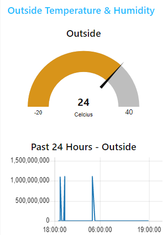
    I've recently been updating my nodes and gateways to use the latest version of MySensors. I've also recently acquired a handful of Sensebender Micros and set one up in the pool shed to test/play and get some outside temperature and humidity readings. A problem I found though is that I was getting some anomalous data readings which completely throws off my time period data - see the 24-hour chart below.

    aaae5fee-173f-4a12-96b7-aba8c2da191b-image.png

    Solar flares perhaps? I ruled that out.

    I set up a test last night before turning in for the night and ran it for about 18 hours. I've collected and compared the debug logs of my node with those of the Ethernet and MQTT gateways that I have and found that the node is sending a valid float value at all times but the gateways will sometimes receive something different.

    Node Debug Data (stripped to just the sending of one of the sensors)

    4935 TSF:MSG:SEND,4-4-0-0,s=1,c=1,t=0,pt=7,l=5,sg=0,ft=0,st=OK:21.6
    5480 TSF:MSG:SEND,4-4-0-0,s=1,c=1,t=0,pt=7,l=5,sg=0,ft=0,st=OK:21.2
    6891 TSF:MSG:SEND,4-4-0-0,s=1,c=1,t=0,pt=7,l=5,sg=0,ft=0,st=OK:20.7
    8331 TSF:MSG:SEND,4-4-0-0,s=1,c=1,t=0,pt=7,l=5,sg=0,ft=0,st=OK:20.4
    

    And corresponding receives from the Ethernet Gateway debug log

    Jun 04 00:55:20 DEBUG TSF:MSG:READ,4-4-0,s=1,c=1,t=0,pt=7,l=5,sg=0:21.6
    Jun 04 01:02:35 DEBUG TSF:MSG:READ,4-4-0,s=1,c=1,t=0,pt=5,l=5,sg=0:1101633946
    Jun 04 01:37:38 DEBUG TSF:MSG:READ,4-4-0,s=1,c=1,t=0,pt=7,l=5,sg=0:20.7
    Jun 04 02:13:52 DEBUG TSF:MSG:READ,4-4-0,s=1,c=1,t=0,pt=7,l=5,sg=0:20.4
    

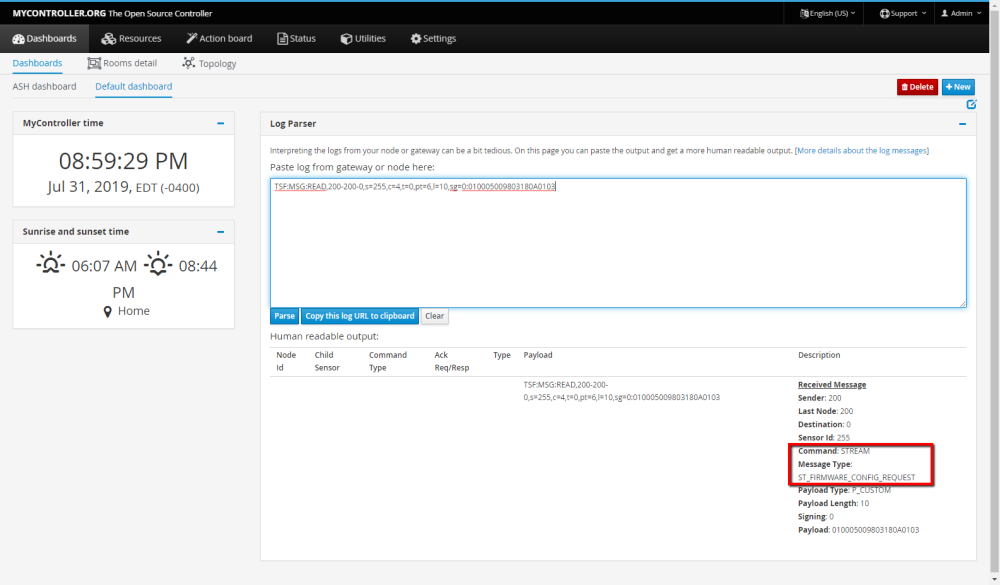
    You can see that the data received changed payload type from P_FLOAT32 (pt=7) to P_ULONG32 (pt=5) !!!

    Note that the graph above is from data collected by way of the MQTT gateway and as such doesn't specifically correspond to the debug logs above but I do see exactly the same flip of payload type in the MQTT GW log - though at different times from those in the Ethernet GW log

    Now I understand that this is going to come down to noise in the radio transmission but it raises some bigger-picture questions for me.

    1. How can I ensure that the data received by the gateway is specifically what the node sent?
    2. Would using ACK and having the node confirm if what was sent was received correctly be a valid approach?
    3. Would implementing message signing help in any way?

    I'm at a loss on how best to ensure the integrity of the data being sent and collected. What are your thoughts?

    Allen

    Troubleshooting

  • Anyone using/tried the E28-2G4M27S 2.4Ghz LoRa SX1280 27dB module?
    A alphaHotel

    @NeverDie said in Anyone using/tried the E28-2G4M27S 2.4Ghz LoRa SX1280 27dB module?:

    @Larson said in Anyone using/tried the E28-2G4M27S 2.4Ghz LoRa SX1280 27dB module?:

    @NeverDie said in Anyone using/tried the E28-2G4M27S 2.4Ghz LoRa SX1280 27dB module?:

    0.4mm diameter Kester Rosin solder.

    I'll put it on my list. After the Male/Female antennae discussion above, I'm sure I got my order wrong - so I'll have a new running list shortly when everything arrives. I checked my solder with a caliper since the dimensions are listed in Chinese: it is 0.6 mm so I'm not far away. I do like the feel the smaller diameter has in comparison to my larger solder so I'm sure 0.4 mm will even be better.

    Yeah, I was using 0.635mm MG Chemicals solder previously, but I found I had to drown the radio modules in rosin flux afterward to eliminate solder bridges, etc. Perhaps part of the difference may be that Kester uses a different formulation for its in-line flux than MG Chemicals? I suppose that could also have something to do with it. So, maybe it's not entirely diameter, but having now worked with the two different diameters, my gut intuition is that the smaller diameter is helping.

    Anyone else reading this having any opinions on the matter that they are willing to share?

    I swear by the stuff in the picture below. It melts at a lower temperature(179 C) so, as an amateur, I feel safer keeping my iron at a lower temp and in place a little longer when I am working with IC's. I like that it's thin too as it is easier to control how much you apply. I have no issues with it, it flows well and doesn't create bridges (unless I use too much).

    PXL_20220609_213636256.jpg

    General Discussion

  • Most reliable "best" radio
    A alphaHotel

    @Larson said in Most reliable "best" radio:

    To extract the *.rar in Windows 10, I downloaded a utility program (WinZip 21-day trial).

    7-Zip is an open-source alternative that will do the job equally as well. https://www.7-zip.org/

    General Discussion

  • Bootloading a barebones arduino
    A alphaHotel

    Well done, forging ahead, @Larson. I wouldn't jump straight to trying to program a bootloader just yet though, we need to finish confirming communication with the chip and then if/when we get that going, look at how the fuses are set.

    Looking at your post here, I believe you got these 328p's from Aliexpress (or similar). Did the listing indicate whether there was a bootloader or not? Bare chips, should be factory set to operate on the internal 8MHz oscillator, so that shouldn't be the problem. How many did you buy?

    Based on your results above, at this point, it would seem that one of the following conditions exists:

    1. There are solder bridges (shorts) somewhere - need to test with a MM in continuity mode, each pin with all other pins. Some should be connected (GNDs for example), but most should not.
    2. The connections from your USBasp to the chip are incorrect. Again, you should be able to check this with a multimeter in continuity mode.
    3. The chip is dead. (Long live the chip.)
    4. The fuses are set to require an external crystal that doesn't exist. I just tested this by setting the fuses on my minimal 328P setup (see picture below). The result of which is that I now get the same error that you are getting. This is not likely the case for you but it is a possibility.

    Here's a pic I just did checking continuity between the MISO contact on the USBasp and the corresponding chip pin on a minimal setup 328P for reference. Disregard that my multimeter is indicating no continuity, (my son took the picture at a bad time as I was making/breaking contact), you'll get the point of the shot though.

    PXL_20220720_032211427.jpg

    Also, take a close-up picture of the board/chip and post it here for us to see what you've got going on.

    Carry on.

    AH

    EDIT: to add the 4th possible condition.

    General Discussion

  • Bootloading a barebones arduino
    A alphaHotel

    @Larson said in Bootloading a barebones arduino:

    Manufactures probably have to make assumptions on this and the prevailing one would probably be for a 16 Mhz crystal.

    If it's straight from the factory, the fuses will be set to use the internal oscillator and there will be no bootloader.

    Looking at your pictures, the chip is well aligned and in the correct orientation. If you're confident in your connections and the USBasp is working well with the Nano but not this chip, then I suspect that the chip was destroyed while being soldered. The fuses-set-for-external-clock possibility is very unlikely and probably not worth the effort to try to test/debug/rectify.

    [Side note @NeverDie: I see that you used D20 and D21 to control the LEDs on board. You might want to make a note on the OpenHardware.io page that users will need to utilize either direct Port B manipulation or MCUDude's MiniCore to control those and no crystal can be added to this board (unless you hack the LED and resistor pads to do it).]

    @Larson, as you have a few more of those chips, I'd suggest putting this one aside for now and trying again (I'm assuming you have at least 2 other copies of V001 boards as OSHpark tends to sell them in 3-packs). If you want to hold off for a bit to wait for that cool clamshell thing, you might also want to consider ordering the V003 boards while you wait so as to avoid the problem with the traces under the battery holders.

    AH

    General Discussion

  • 💬 MySensors Library - v2.x
    A alphaHotel

    There's a broken link in the reference for MY_OTA_FIRMWARE_FEATURE in the Configuration section above (https://www.mysensors.org/download/sensor_api_20#configuration). I believe the correct URL should be https://www.mysensors.org/about/fota.

    Announcements

  • 💬 Version 3.0 atmega328p test platform
    A alphaHotel

    @NeverDie I hit up Keystone Electronics for a 3D model of the battery clip (p/n 92) and then did a little work on setting up 3D models of 2 and 4 of them together - though the 4-piece model is based on the spacing of 16.8mm between centres. If you're interested, I'll share them in a Github repository, since I can't upload them here.

    bb7663eb-dff6-471a-8b0d-86f6af6cfa67-image.png

    OpenHardware.io

  • MY_DEBUG_OTA results in compile errors
    A alphaHotel

    Figured out that I misunderstood the purpose of this directive. I was thinking (had assumed) that it was showing more verbose information through the serial output for firmware OTA update traffic. Once I looked at the description for it, it was clear that it is intended more as an alternative to MY_DEBUG - as in don't send debug output to the serial but send it over-the-air instead. I was declaring both and they conflict.

    EDIT: saying they conflict is inaccurate. The problem was in how I was using it (inappropriately).

    -- Allen

    Development

  • Best way to share a *complete* set of KiCAD design files?
    A alphaHotel

    I've only just started playing with KiCad 6.0 myself. I'm liking it too. I picked it up in order to have a closer look at @m26872 's contribution of KiCad design files from 2015 (using KiCad 4.0 RC2!) for their Slim 2xAA Battery Node.

    They seemingly created the zip file by simply creating a Zip file of the folders that contain the project. That may be the best approach.

    I've been able to open it and although had some challenges remapping the libraries, as they were changed significantly between 4.0 and 5.0, I've been able to have a good look and have plans to change the orientation of the ICSP header to the edge of the board, if I can learn enough to do that.

    As a test of that theory and as a contribution back to the community and @m26872 I tried to upload my copy of the design files in KiCad v 6.0 format but ZIP files are not allowed anymore.

    General Discussion

  • 💬 Version 3.0 atmega328p test platform
    A alphaHotel

    @NeverDie said in 💬 Version 2.0 atmega328p test platform:

    Yes, please! Sounds like it may be very useful!

    Here's the repo. I only just now created the footprint for the 2-clip version so check measurements and such. Also, when I attach the 3D model to the footprint, I had to change the orientation 180 degrees and offset it by the thickness of the board and had to scale it 0.4 in X, Y, and Z dimensions. Hope it helps.

    OpenHardware.io

  • MY_DEBUG_OTA results in compile errors
    A alphaHotel

    @mfalkvidd Thank you - MY_DEBUG_VERBOSE_OTA_UPDATE does look like it's exactly what I was looking for. Further looking into the code here though, it would seem that it gets defined automatically if we define MY_DEBUG.

    Turn it around, when we define MY_DEBUG, we should see verbose FOTA (+ Core, Transport and Gateway) information in the serial log output.

    I'll attempt some more testing tonight to see what I can see.

    Development

  • Best way to share a *complete* set of KiCAD design files?
    A alphaHotel

    I just saw on the openhardware.io site that you can import GitHub projects. That would be a great way to do it. Work locally, push changes to Github, and publish to openhardware.io when it's ready.

    General Discussion

  • 💬 Version 3.0 atmega328p test platform
    A alphaHotel

    @NeverDie In considering a version 3, please consider turning the via in the following picture into a through-hole. it would allow for easier connection of a reset pin if needed to program the 328p with a programmer. b6f549a0-a6a4-4729-80cf-842199b6f1e4-image.png

    OpenHardware.io

  • MySensors SI7021 Library
    A alphaHotel

    I've taken it upon myself to isolate the Si7021 Library found within the MySenesorsArduinoExamples repository and create a modern-style repository specific to the pared-down version from the examples and its use with MySensors sketches. The repository I created is ready to be submitted for inclusion in the Arduino Library Registry which would allow for easy download, installation and use by any user including from within the Arduino IDE or PlatformIO.

    @hek @Yveaux @marceloaqno
    The purpose of my post here is to ask permission to transfer ownership of the repository to the MySensors Organization on Github. as I feel that is where it should live. After that, I can create the pull request(s) needed to finalize the submission of the library to the Arduino Library Registry.

    You can find my repo on Github.

    General Discussion

  • Most reliable "best" radio
    A alphaHotel

    @NeverDie said in Most reliable "best" radio:

    As a result, I just now ordered some of these E01-2G4M27D

    Please let us know if they arrive with or without antennas. I've been eyeing them recently but haven't pulled the trigger yet.

    General Discussion

  • Most reliable "best" radio
    A alphaHotel

    @NeverDie said in Most reliable "best" radio:

    It does already have 100n (=0.1uF) across the DC power line, extremely near the inputs to the nRF24L01

    Add a 10uF cap there. I found these radios are more stable with enough power to draw on during transmission.

    General Discussion

  • Most reliable "best" radio
    A alphaHotel

    @NeverDie said in Most reliable "best" radio:

    @alphaHotel said in Most reliable "best" radio:

    @NeverDie With the first version of the battery/MCU board, you lamented running traces directly under the batteries. You have the space now to re-route them but choose not to. Did you find a way to resolve the issue it caused?

    Actually, I fixed it on the new version (pictured above). The red traces run on top, so they're adequately isolated from the battery holder metal, which is on the back side except for the through-holes where it sticks through the board. Where I ran into trouble was running traces on the back side, beneath the battery holder metal. If the battery holder metal was pressed up hard against the board, some shorts resulted on some of the boards. The workaround was to not press the battery holder metal hard up against the board, but the new version removes that concern entirely.

    Okay, I see now. I misunderstood the original issue and also didn't think about the top/bottom side orientation in relation to those traces vis-a-vis the battery holders. Thanks for clarifying.

    General Discussion
  • Login

  • Don't have an account? Register

  • Login or register to search.
  • First post
    Last post
0
  • OpenHardware.io
  • Categories
  • Recent
  • Tags
  • Popular