@Larson said in Bootloading a barebones arduino:
I'm now talking to the chip in CMD terminal.
Well done! Let us know how it goes from here.
AH
@Larson said in Bootloading a barebones arduino:
I'm now talking to the chip in CMD terminal.
Well done! Let us know how it goes from here.
AH
@NeverDie Jonathan Oxer a little while back went through a similar process with programming headers for ESP8266/ESP32 boards. He discusses some of the challenges and tradeoffs in his video(s).
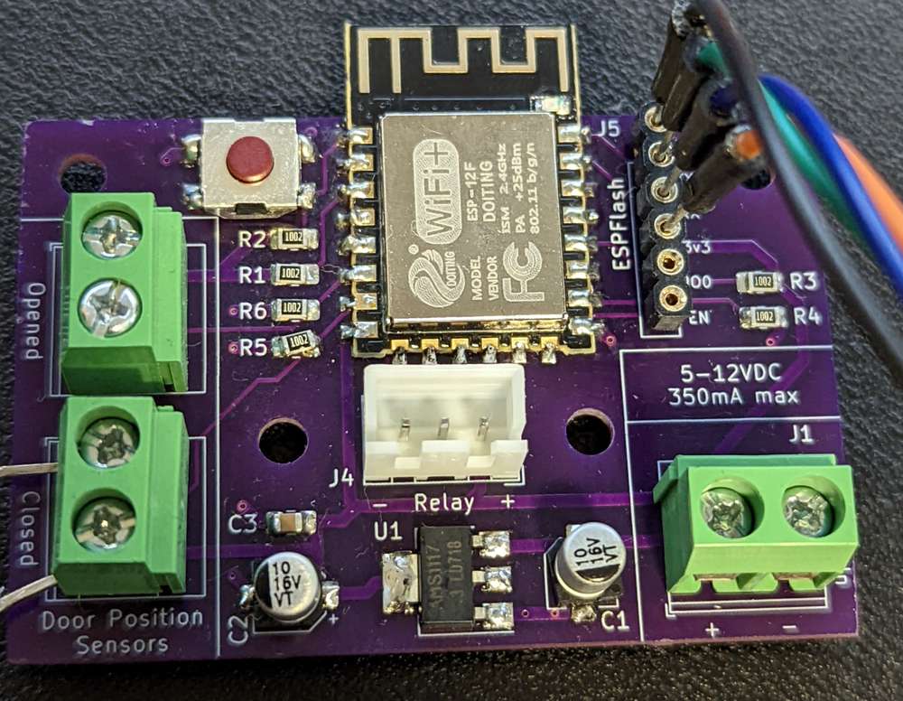
My personal opinion on trying to shrink them down is to keep with pin headers and just make them smaller. It's easy enough to find 1.27mm pitch IDC connectors. Your JST connector idea is good too. In the end, this is mostly a target audience scenario, it seems to me. My most recent board (still working on it), employed Oxer's ESPFlash header but I kept it with a 2.54mm pitch package because I have a ~million headers with that spacing and I wasn't cramped for space. (pic below)
If it's board-to-board as in connecting a radio module to an MCU backplane, then it's more of a use-case and dealer's choice scenario, in my mind. Those Molex SlimStack connectors look interesting.
I don't know if that helps or if I'm blowing smoke in the wrong direction. Just adding my voice.
@NeverDie said in Most reliable "best" radio:
I suppose it's more or less a conventional custom-built bed-of-nails.
:joy: :sunglasses:
@Larson said in Bootloading a barebones arduino:
Manufactures probably have to make assumptions on this and the prevailing one would probably be for a 16 Mhz crystal.
If it's straight from the factory, the fuses will be set to use the internal oscillator and there will be no bootloader.
Looking at your pictures, the chip is well aligned and in the correct orientation. If you're confident in your connections and the USBasp is working well with the Nano but not this chip, then I suspect that the chip was destroyed while being soldered. The fuses-set-for-external-clock possibility is very unlikely and probably not worth the effort to try to test/debug/rectify.
[Side note @NeverDie: I see that you used D20 and D21 to control the LEDs on board. You might want to make a note on the OpenHardware.io page that users will need to utilize either direct Port B manipulation or MCUDude's MiniCore to control those and no crystal can be added to this board (unless you hack the LED and resistor pads to do it).]
@Larson, as you have a few more of those chips, I'd suggest putting this one aside for now and trying again (I'm assuming you have at least 2 other copies of V001 boards as OSHpark tends to sell them in 3-packs). If you want to hold off for a bit to wait for that cool clamshell thing, you might also want to consider ordering the V003 boards while you wait so as to avoid the problem with the traces under the battery holders.
AH
Well done, forging ahead, @Larson. I wouldn't jump straight to trying to program a bootloader just yet though, we need to finish confirming communication with the chip and then if/when we get that going, look at how the fuses are set.
Looking at your post here, I believe you got these 328p's from Aliexpress (or similar). Did the listing indicate whether there was a bootloader or not? Bare chips, should be factory set to operate on the internal 8MHz oscillator, so that shouldn't be the problem. How many did you buy?
Based on your results above, at this point, it would seem that one of the following conditions exists:
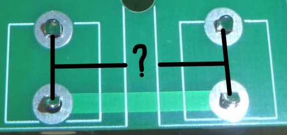
Here's a pic I just did checking continuity between the MISO contact on the USBasp and the corresponding chip pin on a minimal setup 328P for reference. Disregard that my multimeter is indicating no continuity, (my son took the picture at a bad time as I was making/breaking contact), you'll get the point of the shot though.
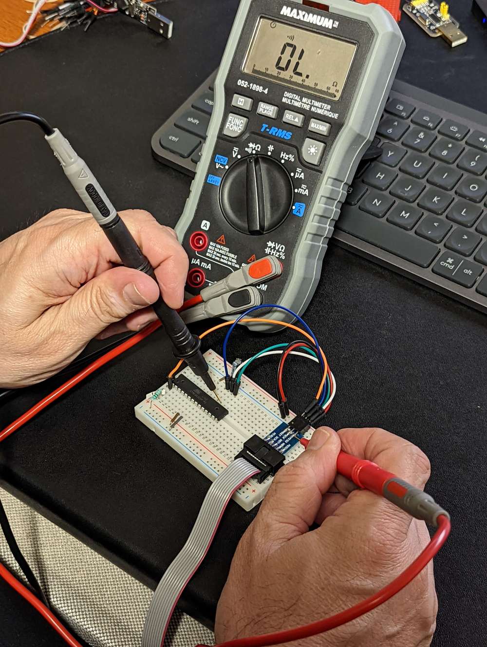
Also, take a close-up picture of the board/chip and post it here for us to see what you've got going on.
Carry on.
AH
EDIT: to add the 4th possible condition.
Hi @GertSanders,
Do you happen to still have the Eagle project files from version 3 you created and shared on OSH Park? I'd like to add a set of pads for the mini smd version of the NRF24L01. If not, I'll just use the version 2 files from openhardware.io and try my best to recreate the changes you made between them.
Kind regards,
AH
@NeverDie Awesome. thanks.
@NeverDie In considering a version 3, please consider turning the via in the following picture into a through-hole. it would allow for easier connection of a reset pin if needed to program the 328p with a programmer. 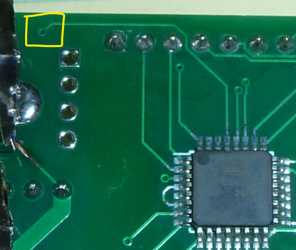
@Larson said in Most reliable "best" radio:
I don't think I can reach the fuses if the 'target' chip doesn't have a bootloader. Do I have that wrong?
You can reach (read/write) the fuses with a USBASP regardless of whether there is a bootloader. If you have any troubles, shoot me a message in the chat or start a new thread somewhere and I'll help you through it.
@NeverDie said in 💬 Version 2.0 atmega328p test platform:
They're onlly there in case you don't have any interest in measuring current and, thus, don't care to install the 4 header pins or the header pin jumpers.
Thank you for providing this insight. I enjoy learning by trying to understand someone else's perspective. It's not always provided as clearly or freely as you have (and do). Very much appreciated.
@alphaHotel said in 💬 Version 2.0 atmega328p test platform:
had to scale it 0.4 in X, Y, and Z dimensions
Update: That's only with the WRL (VRML) files as that file format is "dimensionless" it seems. I'm just learning FreeCAD for manipulating these 3D models so this is my learning curve. The preferred 3D model for CAD programs is STEP and with those, I didn't have to scale or more precisely the scaling factor is the default 1.0. I may remove the WRL files from the repo.
@NeverDie I wanted to have a closer look at your rev 2 but didn't see a RAR archive of the Kicad project. Don't upload it now though, I can wait for rev 3 for that. In looking at the schematic though, a question came to mind. What's the purpose of the 2 zero ohm bridging resistors, R6 & R7 in the schematic? Could you use a solder jumper/bridge there instead for the same purpose?
@NeverDie said in 💬 Version 2.0 atmega328p test platform:
Yes, please! Sounds like it may be very useful!
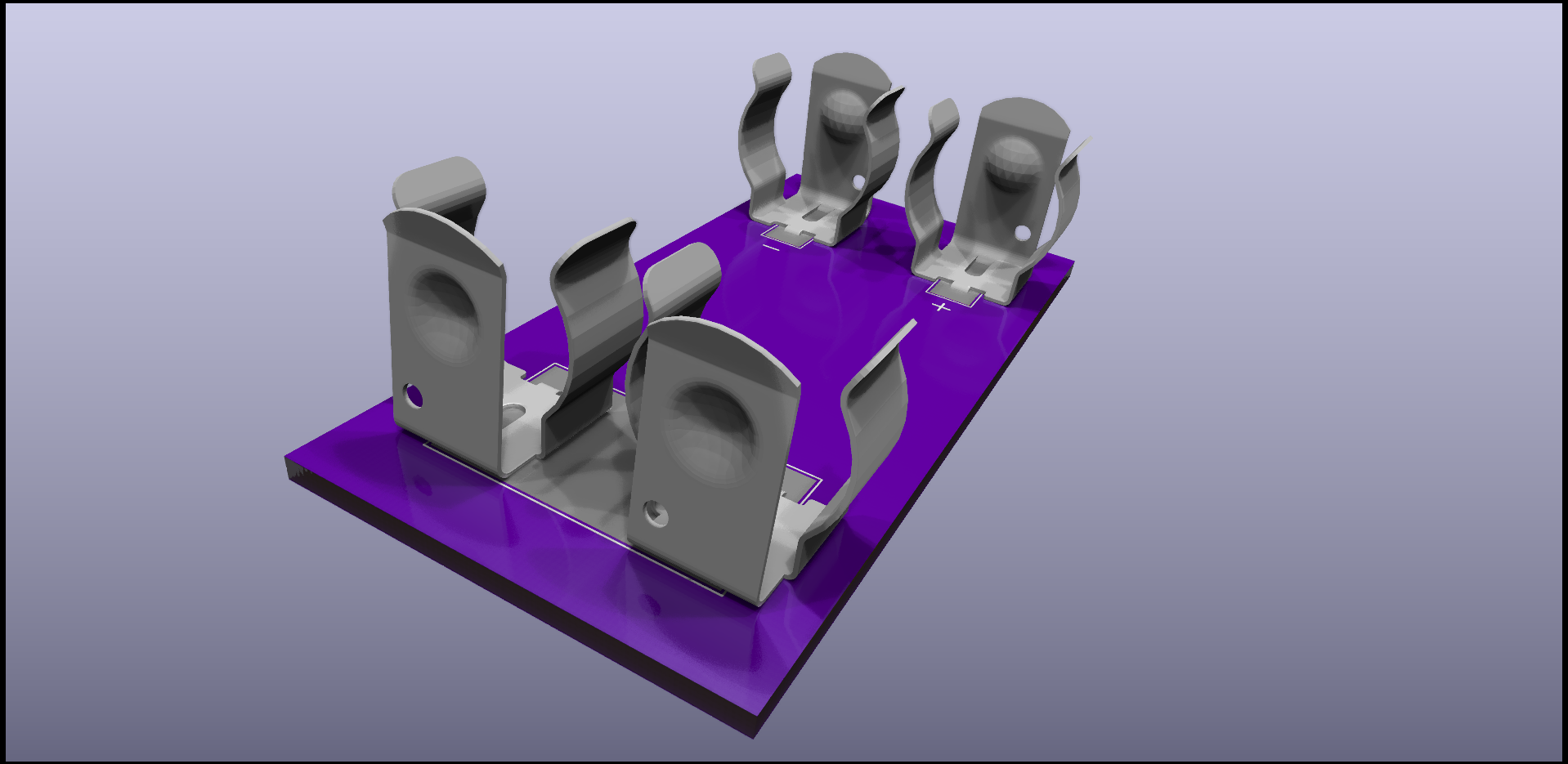
Here's the repo. I only just now created the footprint for the 2-clip version so check measurements and such. Also, when I attach the 3D model to the footprint, I had to change the orientation 180 degrees and offset it by the thickness of the board and had to scale it 0.4 in X, Y, and Z dimensions. Hope it helps.
@NeverDie I hit up Keystone Electronics for a 3D model of the battery clip (p/n 92) and then did a little work on setting up 3D models of 2 and 4 of them together - though the 4-piece model is based on the spacing of 16.8mm between centres. If you're interested, I'll share them in a Github repository, since I can't upload them here.
@Larson said in Most reliable "best" radio:
My problem today is bootloading the brand new 328's with my old USBASP. The IDE says something about “cannot set SCK period” and then “initialization failed”.
If you have a second USBASP or an Arduino of some sore lying around, you could try to update the firmware on the USBASP. I recommend this edition, latest release and a Google search for "how to update usbasp firmware". You may see that with release v1.06 of that repository, there was an improvement that "Includes automatic SCK slowing".
Of course, the problem may be more rudimentary. Can you read the fuses? Are they set to use an external oscillator that doesn't exist?
@NeverDie I thought your turnaround time was decent compared to mine. It has been taking up to 3 weeks for me to get mine from OSHpark. The last fab I ordered, I priced it out at PCBway but they were $29 versus OSHpark's $16. I do find though that within days of sending it off for fabrication, I'm making improvements to the design and kicking myself for placing the order too soon.
@NeverDie, Thank you.
@NeverDie said in Most reliable "best" radio:
I widened the separation between the batteries, and now the clips aren't at risk of shorting against one another.
It's looking good! I'm curious, how far apart are the battery clips now (center-center)? I noted on the original board layout it was 15.62mm. I'm guessing it's about an extra 3mm based on the lines of the silkscreen and the size of the mounting holes you added.
Also, an off-topic question for you - I believe I read in a thread somewhere recently (not sure which one though) that when adding a USB port you prefer USB Mini. Which footprint do you like to use and where do you source them from?
@NeverDie said in Most reliable "best" radio:
@alphaHotel Reporting back: I received them, and mine did not come with any antennas.
That's as I expected too because of the lack of any photos in the listings. Thanks for confirming, it's good to know. I do have a handful lying around from old WiFi routers as you mentioned.
@Larson said in Most reliable "best" radio:
Yes, I think I got your version from Github. I will learn how to send a pull request. Cool, so this is how collaboration works? I'm new to this.
Please don't add to your personal learning curve to create a pull request. It's not that important, at all.