@skywatch Yes ... RTFM ... So simple :grin:
B
barrydou
@barrydou
Posts
-
[SOLVED]Atmega 328P reset to start -
[SOLVED]Atmega 328P reset to startI've just found it !
I added a 100nf caps between VCC and GND, just near pin 7 and 8, like documented on the MiniCore github page.
https://github.com/MCUdude/MiniCore => DIP-28 package ATmega8/48/88/168/328And now, it's work as expected. I just plug VCC and GND, and the led blink twice per second.
Don't know why, but it's OK :grinning:
Thank you for all your ideas
-
[SOLVED]Atmega 328P reset to start@skywatch said in Atmega 328P reset to start:
@barrydou said in Atmega 328P reset to start:
@skywatch
Yes after flashing MiniCore, the led flash twice per second.That is good!
If I keep only VCC, GND, pullup on Reset and the led on D13, I unplug / replug the power => Nothing, until I force a reset (GND on Reset pin)
How are you removing the power and for how long? Try 30 seconds before reconnect.....
I unplug the vcc dupond cable from breadboard (beetween power source and breadboard). And I plug it again.
Before this message, I unplug during a few seconds. I try 1 minute now, it's the same.When I force, the led flash twice per second (even without clock, but the fuses are set to 8Mhz Internal)
That is contradictory - it is not 'without clock' if the fuses are set to 8MHx internal - it has 8MHz internal clock running.....OR maybe I mis-understand?
Sorry, I mean without external clock. I remove external Quartz and Caps just after flashing the minicore
-
[SOLVED]Atmega 328P reset to start@skywatch
Yes after flashing MiniCore, the led flash twice per second.
If I keep only VCC, GND, pullup on Reset and the led on D13, I unplug / replug the power => Nothing, until I force a reset (GND on Reset pin)
When I force, the led flash twice per second (even without clock, but the fuses are set to 8Mhz Internal) -
[SOLVED]Atmega 328P reset to startHello
I have 4.8V on the reset pin (directly mesured on the DIL package). I use a 10k pullup resistor.
The atmega was on a single board with uno bootloader before. It was working great, and the reset pin was not connected at all (only vcc/gnd/D2/D4 and clock where connected before I put it on the breadborard)I've tried with 10k resistor, without resistor (reset floating), with caps. Always the same thing
-
[SOLVED]Atmega 328P reset to startHello
I just get a Atmega 328P in DIL package. It was configured with external 16Mhz clock.
I set up it with internal 8mhz and minicore bootloader with Arduino IDE and Arduino as ISP
Here is the configuration I used
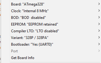
Burning the bootloader works well. I follow this guide for wiring, and I add a led on D13 with a 1k resistor to GND.After burning the bootloader, the led was blinking as usual. I was happy :)
But, after that, I unplug the arduino as ISP, the clock source, and replug only power source. The led was not blinking anymore. :angry:
I replug the arduino as ISP (not the clock), and use AVRDUDESS to read fuse, and miracle the led restart to blink :grin:
Here is the fuses readed
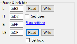
I unplug everything again, and replug only power source ... no blink :flushed: . And I don't know why, I try to send reset (GND to Reset Pin), and blink started.I've tested it and retested it, the led don't start to blink until I send reset.
Any ideas of why I need to reset to start the arduino ? Is there any fuse or lock that configure it ? Something I miss ?
Thank you for your help
-
DIY RFM69 BuildHello
Have you seen this thread ? Thery talk about G4C .
https://lowpowerlab.com/forum/rf-range-antennas-rfm69-library/designing-a-better-rfm69-radio-module/Here is other informations about GaAs
https://www.psemi.com/pdf/app_notes/an18.pdfNot sure to have understood everything :)
-
RFM69hcw (arduino pro mini) not finding parent (esp8266)Hello
Where is connected the RST pin of the radio board ? It seems to be connected to pin 9 of arduino.
On the connecting radio page, it's said : "* Adafruit modules need RST connected to GND".
Have you try it ?You could also try to add RFM69 trace.
#define 	MY_DEBUG_VERBOSE_RFM69
#define 	MY_DEBUG_VERBOSE_RFM69_REGISTERS
But I don't know how to read those debug traces...
Editing : I've not seen that it's already activated, sorryHope it could help, I'm still mysensors newbie :)
-
Help to identify Arduino pro mini clone componentsThank you so much.
I did not found any schematic for those boards. And the diode and polyfuse are not on the sparkfun design.
The diode let me crazy when trying to verify and trace the signal with multimeter. I take a long time before understanding why my multimeter some times say connected, sometime say not connected. And this night, I tell myself : it's a diode :)
Thank you again !
-
Help to identify Arduino pro mini clone componentsHello
I have some Arduino pro mini Chineese clones which are not exactly made like original. I know it's normal :)
I m trying to recognize components but i m note sure.
Here is a picture of the part or the card.

I Hope the number i ve added are visible.
So what is
1: no Idea.
2: a diode
3: voltage regulator
4: led indicating power on
5: resistor for the led 4 ?
6: "small" capacitor on vcc ?
7: "Big" capacitor on raw pin ?
8: "Big" capacitor on vcc ?
9: "small" capacitor on rst pin ?
10 : oscillatorWithout ?, I'm quite sure. With ? I'm not sure but don't see what else it could be, and no Idea => no Idea 🤣
Thank you for your knowledge
-
[Solved]RFM69 Sleep Mode - high current when sleepingSorry for not giving news.
So I've done lot of tests, triple check everything and still found "nothing"
I test with deepSleep sketch from lowpowerlab, and still have high current.I finally receive new rfm69 and change it. And it's ok now !!!
I have 25uA when sleeping !!!Don't know why, but with new one, it's ok :)
Thank you again for your help and your ideas
-
RPI GW - Configure an ethernet RPI GW that drive an USB Arduino GWHello
I've build a serial gateway with an Arduino Nano connected to my Rpi running Domoticz. Everything is working fine.
But now, I'm looking at FOTA. And I realised that a serial gateway is not really easy to use (my pi and the gateway are in the attic)So instead of running a RPI GW driving a radio on GPIO pin, I'd like to know if it could be possible to configure the RPI GW as ethernet (or MQTT), and drive the Arduino GW on USB. Like that, i'll not have to build a new RPI Hat with a new radio.
The RPI GW, configure as ethernet or MQTT will "hide" the real one.It could do something like :
RFM69(orNRF24) =(wire)=> Arduino Nano =(USB)=> PI GW ==(IP)==> Controllers(Pi/MySController...)What do you think of such feature ?
-
[Solved]RFM69 Sleep Mode - high current when sleeping@evb it's for doing a gasmeter, counting with a reed sensor.
But for my tests, the read sensor is not connected. So nothing wakeup the interrupt.
I just send every 10 minutes the counter, as a keepalive. (Domoticz don't put the sensors as "red" )First, I was doing test with newbie pcb, and I had strange values.
So I remove everything, and I do test with breadboard and dupont cable.I just have the arduino pro mini, and the rfm69 solder on a nrf2rfm69 board and a 0.1uF capacitor.
I have 2AA alkaline battery, connected to the VCC/GND pin of arduino and to 3.3V/GND of NRF2RFM adapter.
I measure the current on the cable between battery + and 3,3V of NRF2RFM69 (like in your photo)I have no scope, so I can't check NSS/MOSI/... and so on. But the transmissions are OK, and everything is working well, except current when sleeping.
I had no time today to do more test today. I will double check everything as soon as possible, try your sketch
-
[Solved]RFM69 Sleep Mode - high current when sleepingHello
Thank you for your time. Here is my complete sketch.
If arduino goes to sleep and wakeup and so on, I think that I'll see lot of messages sended.
I suspect my RFM69 to have some quality problems. But i'm not sure. I'll try to change it. as soon as i will receive new one from china.// Enable debug prints to serial monitor #define MY_DEBUG // Enable and select radio type attached #define MY_RADIO_RFM69 #define MY_RFM69_NEW_DRIVER #include <MySensors.h> #define DIGITAL_INPUT_SENSOR 3 // The digital input you attached your sensor. (Only 2 and 3 generates interrupt!) #define CHILD_ID 1 // Id of the sensor child MyMessage volumeMsg(CHILD_ID, V_VOLUME); MyMessage lastCounterMsg(CHILD_ID, V_VAR1); volatile uint32_t pulseCount = 0; bool pcReceived = false; unsigned long loopNumber = 0; //========================= // BATTERY MEASURER // VOLTAGE DIVIDER SETUP // 1M, 470K divider across battery and using internal ADC ref of 1.1V // Sense point is bypassed with 0.1 uF cap to reduce noise at that point // ((1e6+470e3)/470e3)*1.1 = Vmax = 3.44 Volts // 3.44/1023 = Volts per bit = 0.003363075 #define VBAT_PER_BITS 0.003363075 #define VMIN 2.0 // Vmin (radio Min Volt)=1.9V (564v) #define VMAX 3.2 // Vmax = (2xAA bat)=3.0V (892v) int batLoop = 0; // Loop to help calc average int batArray[4]; // Array to store value for average calc. int BATTERY_SENSE_PIN = A0; // select the input pin for the battery sense point //========================= void setup() { // initialize our digital pins internal pullup resistor so one pulse switches from high to low (less distortion) pinMode(DIGITAL_INPUT_SENSOR, INPUT_PULLUP); pulseCount = 0; // Fetch last known pulse count value from gw request(CHILD_ID, V_VAR1); //Battery analogReference(INTERNAL); //On attend le resultat avant de passer dans la boucle wait(1000); } void presentation() { // Send the sketch version information to the gateway and Controller sendSketchInfo("Gas Meter", "2.0"); // Register this device as Water flow sensor present(CHILD_ID, S_GAS); } //========================= // BATTERY MEASURER void MeasureBattery() //The battery calculations { delay(500); // Battery monitoring reading int sensorValue = analogRead(BATTERY_SENSE_PIN); delay(500); // Calculate the battery in % float Vbat = sensorValue * VBAT_PER_BITS; int batteryPcnt = static_cast<int>(((Vbat - VMIN) / (VMAX - VMIN)) * 100.); #ifdef MY_DEBUG Serial.print("Battery percent: "); Serial.print(batteryPcnt); Serial.print(" %"); Serial.print("Battery Voltage: "); Serial.print(Vbat); Serial.println(" Volts"); #endif if (batteryPcnt > 100) { batteryPcnt = 100; } if (batteryPcnt < 0) { batteryPcnt = 0; } // Add it to array so we get an average of 3 (3x20min) batArray[batLoop] = batteryPcnt; if (batLoop > 2) { batteryPcnt = (batArray[0] + batArray[1] + batArray[2] + batArray[3]); batteryPcnt = batteryPcnt / 4; #ifdef MY_DEBUG Serial.print("Battery Average (Send): "); Serial.print(batteryPcnt); Serial.println(" %"); #endif sendBatteryLevel(batteryPcnt); batLoop = 0; } else { batLoop++; } } void loop() { if (!pcReceived) { //Last Pulsecount not yet received from controller, request it again request(CHILD_ID, V_VAR1); wait(1000); return; } if (loopNumber % 12 == 0) { Serial.println("Measuring Battery"); //========================= // BATTERY MEASURER MeasureBattery(); //========================= } #ifdef MY_DEBUG Serial.println("I'm sleeping"); #endif int8_t cause = sleep(digitalPinToInterrupt(DIGITAL_INPUT_SENSOR), FALLING, 600000); #ifdef MY_DEBUG Serial.print("WakeUp , cause:"); Serial.print(cause); Serial.print("(pin interrupt :"); Serial.print(digitalPinToInterrupt(DIGITAL_INPUT_SENSOR)); Serial.println(";-1=timer)"); #endif if (cause == digitalPinToInterrupt(DIGITAL_INPUT_SENSOR)) { pulseCount++; // softwaredebounce, on ignore toute entree pendant 100ms wait(100); } #ifdef MY_DEBUG Serial.print("Pulsecount="); Serial.println(pulseCount); Serial.println("Sending pulse Count"); #endif double volume = 0; volume = ((double)pulseCount / ((double)1000)); send(volumeMsg.set(volume, 4)); send(lastCounterMsg.set(pulseCount)); loopNumber++; } void receive(const MyMessage &message) { if (message.type == V_VAR1) { uint32_t gwPulseCount = message.getULong(); if (!pcReceived) { pulseCount = gwPulseCount; #ifdef MY_DEBUG Serial.print("Received last pulse count from gw:"); Serial.println(pulseCount); #endif pcReceived = true; } } } -
[Solved]RFM69 Sleep Mode - high current when sleepingRe: RFM69 sleep mode
Hello
I'm back with my high current in sleep mode. After changing my multimeter, challenging my arduino configuration, doing lot of test loosing my hairs, i finally found that it is my rfm69w that consume 2mA in sleep mode.
I use
#define   MY_RADIO_RFM69
#define MY_RFM69_NEW_DRIVER
to configure RFM69
I sleep wit the sleep functon
int8_t cause = sleep(digitalPinToInterrupt(DIGITAL_INPUT_SENSOR), FALLING, 600000);I measure the current directly in the 3.3V of the rfm69. In the meantime, the arduino mini is less than 50uA.
What could I do debug such a situation ?
Thank you for your help
-
[Solved] Easy PCB - current when sleepingThank you for your answer
I'm trying to compare with only pro mini and rfm69 on a test plate, and 2 AA batteries. I have strange result, and i'm doubting about my multimeter.
I'll continue testing and will tell you -
[Solved] Easy PCB - current when sleepingRe: 💬 Easy/Newbie PCB for MySensors
Hello
I'm building a gas meter sensor with easy pcb, with 3.3v / 8mhz arduino pro mini, a rfm69w (with an nrf2rfm adapter).
I remove led and voltage regulator on the arduino board.
The easy pcb is configured with battery booster and voltage divider (1mohm and 470kohm).
I use internal pullup to get read sensor of the gas meter (pin 3 used with interrupt)Everything is working fine, but when sleeping, my multimeter said 400uA.
In the main time, I have this board from aliexpress, and with the same sketch use 40uA (ten times less), with a voltage regulator included and 16mhz clock
https://fr.aliexpress.com/item/33006101437.html?spm=a2g0o.productlist.0.0.1424881cHzQI0F&algo_pvid=16f38802-af52-43e2-a2d1-7e3c2a84733f&algo_expid=16f38802-af52-43e2-a2d1-7e3c2a84733f-0&btsid=2100bb5116098762728804034e5d33&ws_ab_test=searchweb0_0,searchweb201602_,searchweb201603_Is it normal ? Is it Arduino pro mini that consume much more than the development board? is there a special way to investigate it ?
Thank you for your ideas and advice.
-
Kicad library for dc-dc step up booster@sundberg84 thank you again. I'll do like you say :)
-
Kicad library for dc-dc step up booster@bjacobse I've seen them, but as @sundberg84 asked me, it's already finished booster, the one linked in mysensors store.
I'm looking something like the one used on Easy/Newbie PCB.Can I use something like "Conn_01x03_MountingPin" ?
I'm starting kicad, I already have used easy/newbie pcb for my first sensors, but I need to design a board for an existing raingauge not working anymore (used by an old meteo station). I want to keep the mechanical part, and replace the electronical board.
Thank's for your help