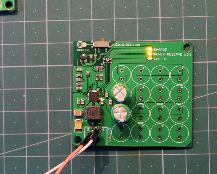
The board charges super capacitors and balances them when the system voltage is available. If this power rail fails, super capacitors power bank takes over and sends power back to the power rail - it acts as uninterruptible power supply.
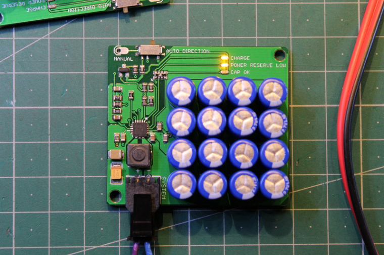
Two capacitors are connected in series, pairs in parallel.
System voltage can be from 3.3V up to 5V. Charging current is 600mA. Backup voltage is 3.15V. The main IC is LTC3110 and it handles all functions of the board.
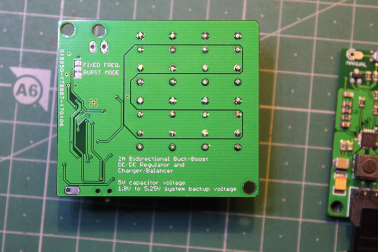
This board is intended to be a test board for super capacitor chargers and can supply backup power for limited amounts of time.
10 boards will shortly be available for sale and design files will be available at OpenHardware.
C
ceech
@ceech
Posts
-
Super capacitor charger/balancer with system backup -
3D pictures from EagleCAD filesWould you like to make some 3D pictures of your PCB? Like this one:
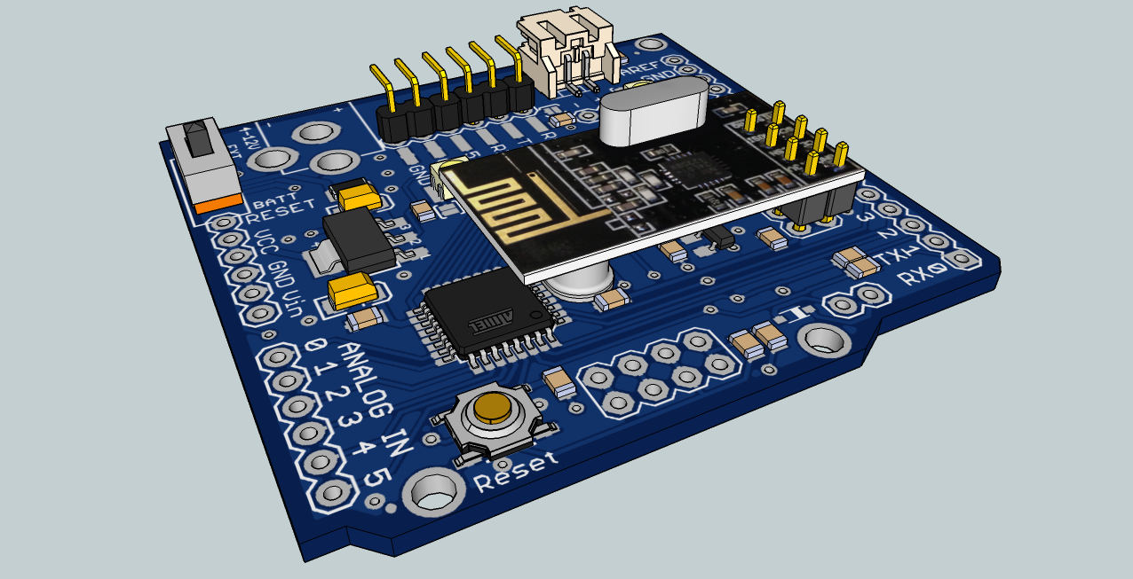
Or some closeups like those:
You can do it with a tool that's called EagleUP. EagleUP exports the data from EagleCAD to Google Sketchup. There you can view, modify and export 3D models.
To run eagleUp you need to download and install:Cadsoft Eagle
Sketchup
ImageMagick and
EagleUPHere is a nice tutorial:
https://eagleup.wordpress.com/installation-and-setup/Enjoy.
-
Ceech board upgradeThe board will receive a new design with TP4056 battery charger.
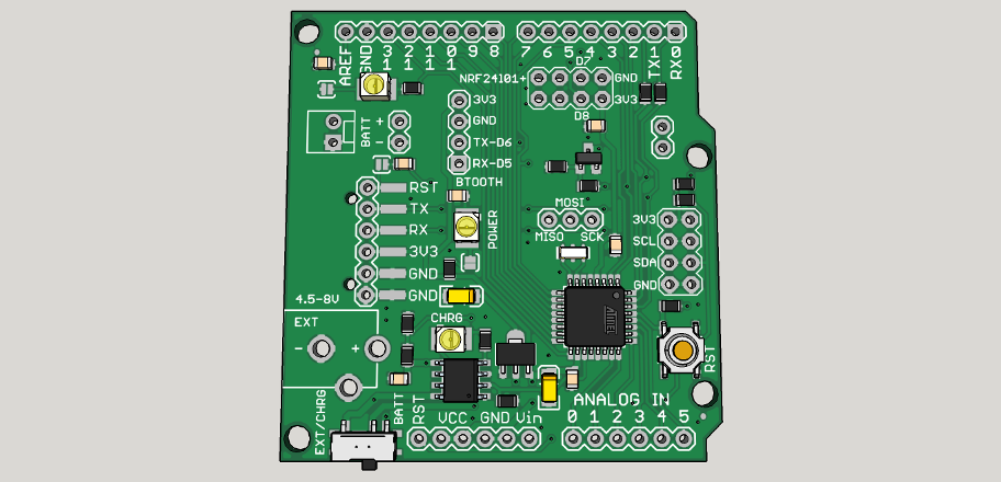
Charge current and battery voltage will be reported on ADC6 and ADC7.
Mosfet will be available for external load regulation. It is connected to D3.
There are three sockets for:
bluetooth
NRF24l01+ and
I2C modules. -
Energy harvesterHere are two new boards. Their purpose is to replace batteries in wireless sensor nodes in places where batteries are not appropriate, available or recommended for use.
The first one is a Thermal Energy Harvester which uses thermopile or thermoelectric generator as a power source:
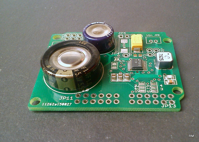
This board uses a transformer to step-up the voltage and works with voltages as low as 20mV. Here is an intended use:
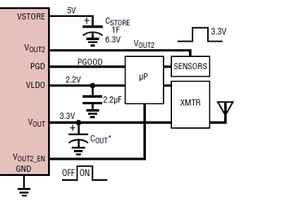
There are three outputs:
Vout
Vout2 and
VLDO
Vout and VLDO turn on as soon as the voltage on those pins is within regulation and Vout2 turns on when the Vout2_EN signal receives a high on its pin from a microcontroller, for example.And the second one is a Solar Energy Harvester which is powered by a small 5 - 20V solar cell:
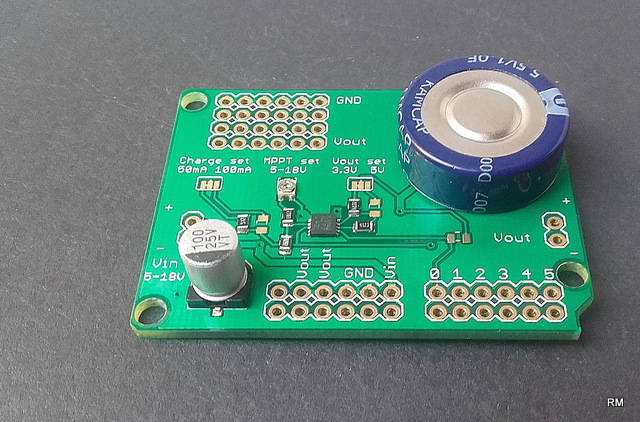
The IC can operate with up to 60V of input voltage and has a built-in CC and CV algorithm.
There are also some settings available for this one:
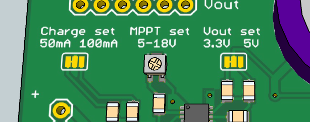
User can choose output voltage and charge current and also MPPT point of solar cell.
This power supply can act as a battery charger as well.Both boards are designed to fit on top of sensor board:
to help with connections -
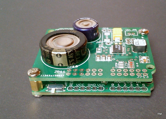
Sensor board w/ liPo charger and fuel gauge +BMP180 +HTU21Finally managed to put all things together and made the first two test boards. They look like this:
Main new features are LTC4067 lithium battery charger and XC6210, a low consumption voltage regulator.The board comes with a Torex XC6210 3.3V voltage regulator . It has low power consumption of 35μA, while delivering at least 700mA. Voltage drop is 50mV @ 100mA.
LTC4067 battery charger with Automatic Battery Charging/Load Switchover
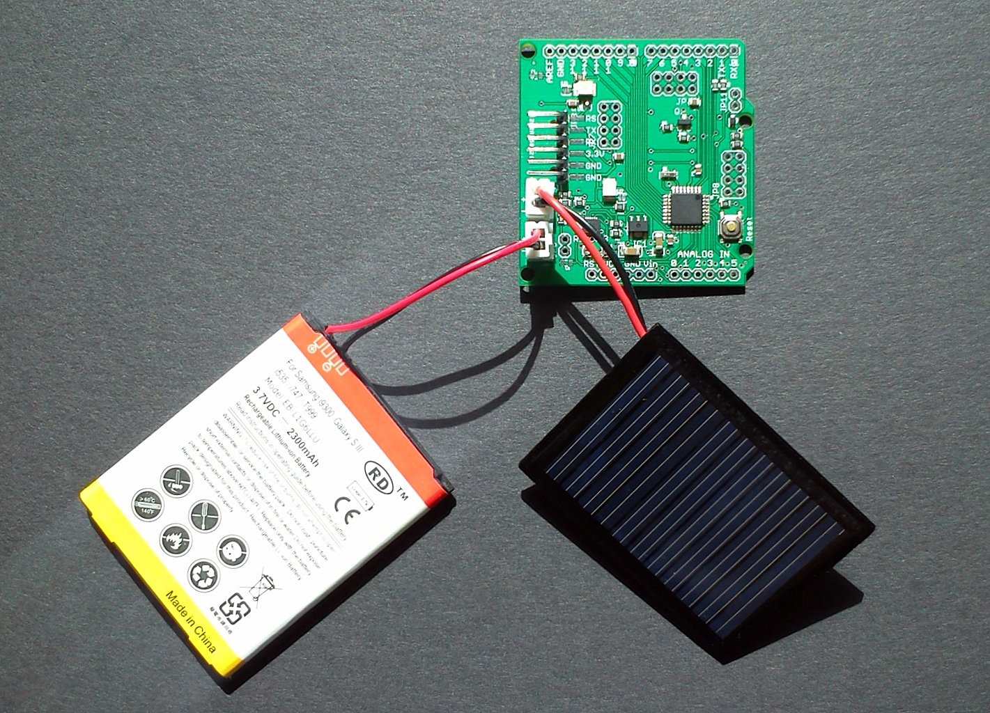
It provides power for the circuit and charges the backup single-cell lithium battery while greatly extends battery life. You can monitor the voltages and currents. It has suspend mode, which reduces current consumption to around 40μA. The power source is a small, 5V solar cell. Connections:
analog input A1 on ATmega 328 is FAULT signal from LTC4067
analog input A0 on ATmega328 is battery voltage
analog input A2 is solar cell voltage
analog input A6 is input current ( I=V/R x 1000 )
analog input A7 is battery charge current ( I=V/R x 1000 )
digital output A9 - drive it high to put LTC4067 in SUSPEND modeThe two trimmer potentiometers are used to determine the current for both the input side - to better match the internal resistance of the solar cell - and for the battery charge current. At shipping they are both set to about 2.5kOhm, which set both currents to about 75mA. Please refer to technical data sheet of LTC4067 for more information. It is available here:
Official web page for LTC4067Or, ask me.
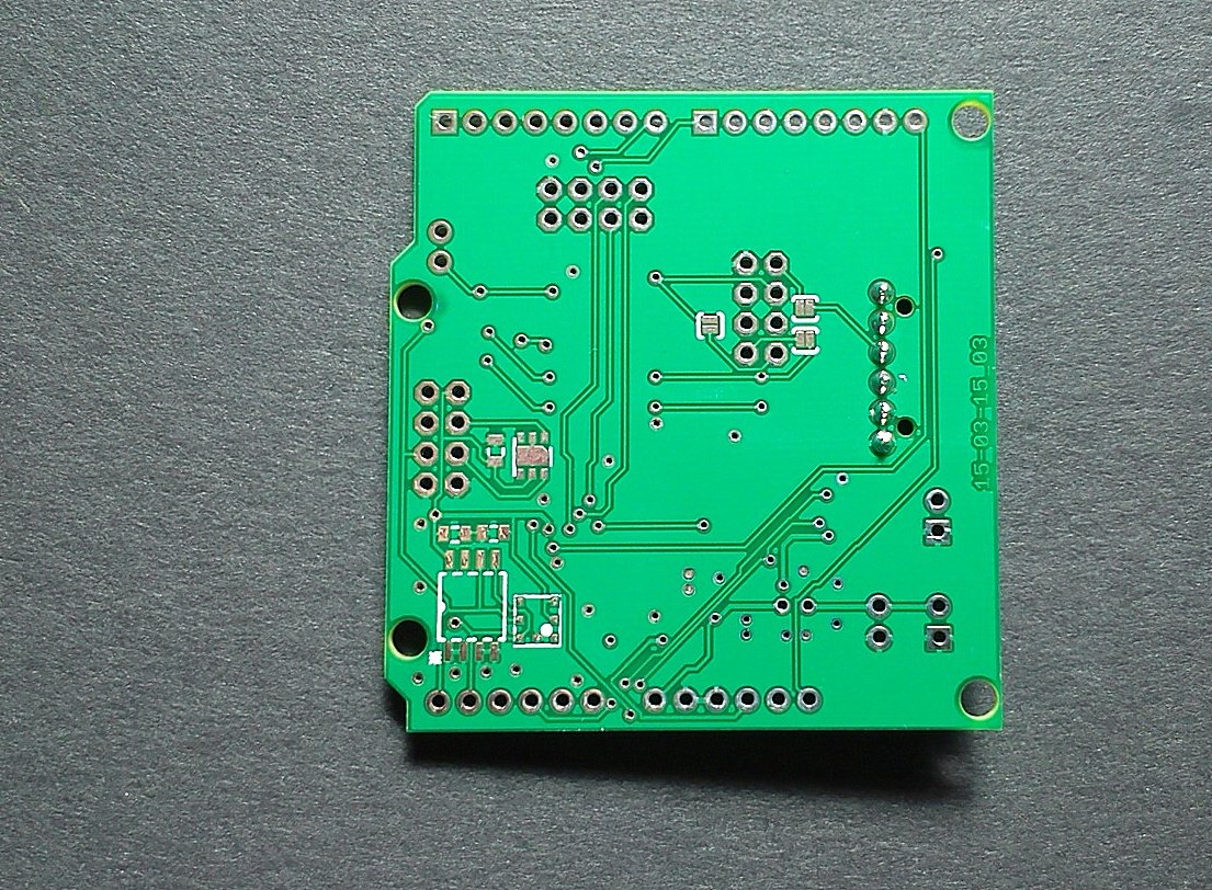
This is the back side of the board with place for BMP180, HTU21 and EEPROM chip:
-
110v-230v AC to Mysensors PCB boardThere is something similar I'm working on. Although mine is more like a solid state relay. And it can be used as an AC dimmer. But has the same concept with AC-DC converter. I used one from Vigortronix. It has a 3.3V output.
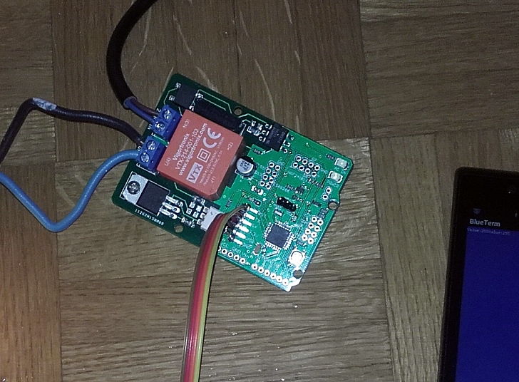
Here it is controlled with Bluetooth serial connection
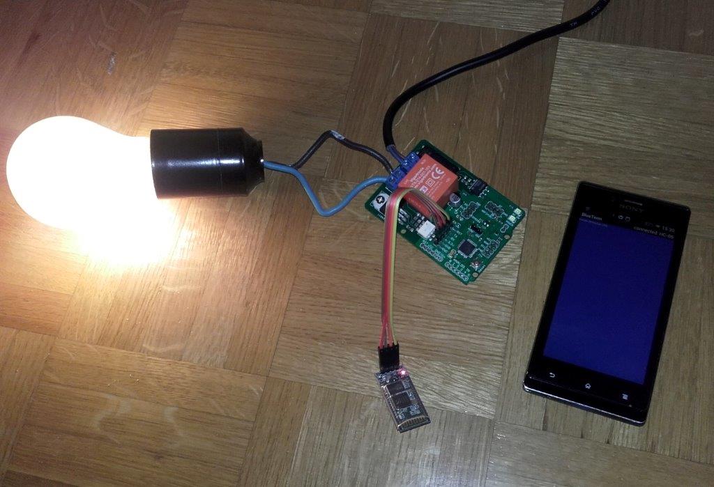
This is how the board looks like
If anyone wants it, let me know.@aproxx I like your form factor. Great find with that AC-DC converter.
-
Recommendation for 12V battery powerThe charger can be something like this one:
http://www.ebay.com/itm/LM2596-DC-DC-Step-down-Adjustable-CC-CV-Power-Supply-Module-Converter-LED-driver-/191673918658?hash=item2ca0a7e4c2:g:4H4AAOSwMmBVo4rQIt has a buck converter with constant current and constant voltage settings which is what batteries need. It can charge any kind of battery with proper float voltage and current settings. If you would go with 4 lithium cells in series you can use the same module to charge the batteries and use it to drive LEDs. Multiple cell lithium batteries normally also need a balancing circuit. Not absolutely necessary, although recommended.
Here is a link to a video on driving LEDs with this converter:
https://www.youtube.com/watch?v=piET0Biqo0I -
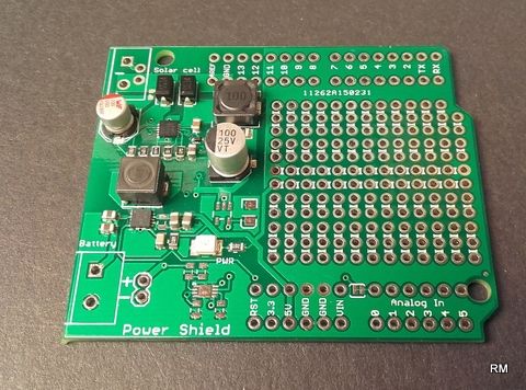
How best to find the "best" small solar panel of a particular size?Anyone interested in super capacitors.
I'm working on a backup super capacitor storage board. It connects directly to the power rail and charges and balances super capacitors bank. When and if power fails the board steps in and provides power to the circuit.
It is based on LTC3110 super capacitor bi-directional charging IC. -
Connecting Gateway to Domoticz@mfalkvidd Removing --my-controller-ip-address did in fact solve the issue.
Thank you for your help.
So, to sum up, these are commands to be used when configuring Gateway for Domoticz ethernet (LAN) connection:./configure --my-transport=nrf24 --my-gateway=ethernet make sudo make install sudo systemctl enable mysgw.service # << adding to boot sudo systemctl start mysgw.service # << starting -
EU flag development boardThere is a project I've been working on that I would like to share. It is not a sensor board for home automation, it is more like a development board. There are some sensors on it which can be used, though. It has BMP180 temperature sensor, a LSM9DS1 3D accelerometer, gyroscope & magnetometer and real time clock. This is how it looks like:
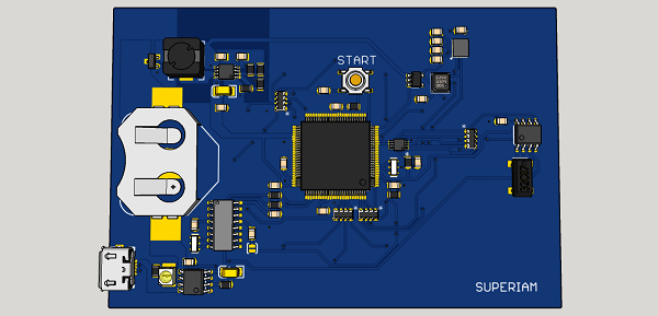

The idea is to use those sensors and display its values on the front of the board. Time for example. Microcontroller is an ATmega 2560 with mega bootloader and is Arduino compatible. It can be powered with a rechargeable coin battery or via USB. I'm working on a prototype at the moment and it will soon be ready.
I made it because I would like to show that Europeans are as much proud of their heritage as Americans and lately Britons.
Is there someone who would like to help write some code for it? And what do you think about it? -
Another possible board - ATMega328, nRF socket, DHT22 socket, MOSFET, Uno pinout@AWI
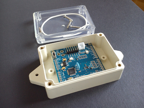
I normally use a 12V car battery, for monitoring different values in the car. When the board is used in single cell battery applications, I go with a different type of voltage regulator. Normally I use TC2117 3.3V voltage regulator. Unfortunately those regulators are not available for purchase either form Farnell nor Microchip at the moment. They will be available on the 9th of March. So a bit of a set back. As for the enclosure, I use this:
And a little 5V solar cell, when appropriate:
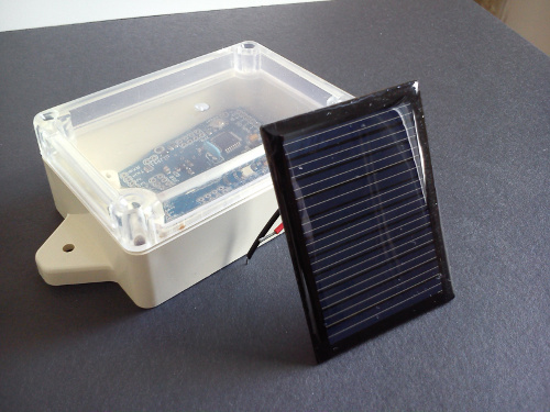
there is also a matter of battery charging, which I leave to this fellow:
http://www.ebay.com/itm/221533778016?_trksid=p2060778.m2749.l2649&ssPageName=STRK%3AMEBIDX%3AIT
I'm also preparing a new board, with integrated battery charger for LiPo, LiIon batteries and some other cool features.
-
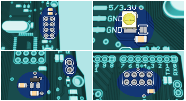
Another possible board - ATMega328, nRF socket, DHT22 socket, MOSFET, Uno pinout@AWI Here is a graphical explanation of the socket connections:
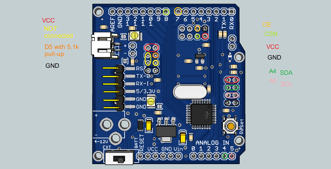
SDA and SCL lines also have pull-up resistors. They are 10k. -
Sensor board w/ liPo charger and fuel gauge +BMP180 +HTU21@lafleur The board is meant to be used with either NRF24l01+, or ESP8266 radio modules. @hawk_2050 The price will be around 14EUR for the version without sensors, and 19EUR for the fully populated one. @Sparkman and @sj44k some boards will be available as soon as next week. Those are the test ones and since everything seem to work excellent, I'll make them available for purchase.
-
Safe In-Wall AC to DC Transformers??@Fabien @DrJeff Here is a link to board and schematic files for the transformerless AC-DC converter:
https://github.com/ceech/AC_SR087 -
Ceech-Board Buyers@doesel33 Your board came back. No one claimed the package at your post office and after two weeks it came back. Take a look, I still have the envelope:
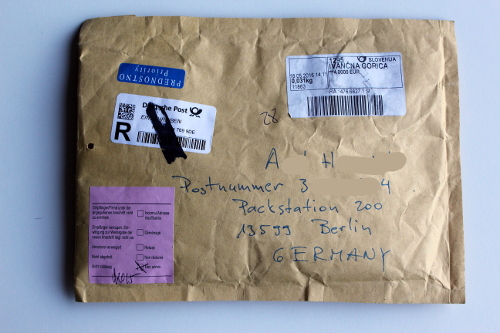
So, what do you want to do with it?
Maybe there is an error in your PaPay entered address or something similar. Would you check that? I'll be happy to send you a package again. -
Ceech board upgradeNew boards are ready and are being tested. Here is one connected to a Bluetooth module charging a battery:
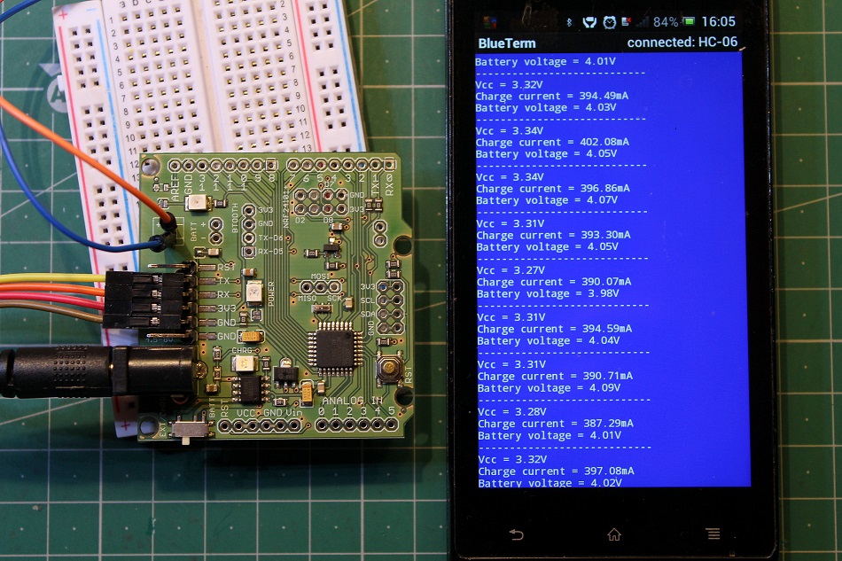
This is the code used in battery voltage and charge current monitoring:
float readVcc()
{
  signed long resultVcc;
  float resultVccFloat;
  // Read 1.1V reference against AVcc
  ADMUX = _BV(REFS0) | _BV(MUX3) | _BV(MUX2) | _BV(MUX1);
  delay(10);                           // Wait for Vref to settle
  ADCSRA |= _BV(ADSC);                 // Convert
  while (bit_is_set(ADCSRA,ADSC));
  resultVcc = ADCL;
  resultVcc |= ADCH<<8;
  resultVcc = 1126400L / resultVcc;    // Back-calculate AVcc in mV
  resultVccFloat = (float) resultVcc / 1000.0; // Convert to Float

  return resultVccFloat;
}

const int current = A6;
const int lipo = A7;


float vout = 0.0;
float vin = 0.0;
int value = 0;

void setup()
{
  Serial.begin(9600);
}

void loop()
{
  float napetost = readVcc();

  float tok = ((analogRead(current) * napetost / 1024 ) * 1200) / 3; // convert the ADC value of charge current to miliamps
  float baterija = ( analogRead(lipo) * napetost / 1024 ) * 2; // measuring battery voltage

  Serial.print("Vcc = ");
  Serial.print(napetost);
  Serial.println("V");
  delay(400);
  Serial.print("Charge current = ");
  Serial.print(tok);
  Serial.println("mA");
  delay(400);
  Serial.print("Battery voltage = ");
  Serial.print(baterija);
  Serial.println("V");
  delay(400);
  Serial.println("----------------------------");
  delay(2000);
}
/*
Improving accuracy:
To do so, simply measure your Vcc with a voltmeter and with our readVcc() function. Then, replace the constant 1107035L with a new constant:
scale_constant = internal1.1Ref * 1024 * 1000
where
internal1.1Ref = 1,1 * Vcc1 (per voltmeter) / Vcc2 (per readVcc() function)
Example:
For instance, I measure 3,43V from my FTDI, the calculated value of Vref is 1,081V.
So (1,081 x 1000 x 1024) = 1107034,95 or 1107035L rounded up.

Use smoothing example from IDE to smooth the data from ADC.
*/
Charge current is limited to 400mA and can be easily changed to another value by changing just one resistor.
-
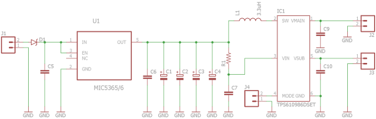
How best to find the "best" small solar panel of a particular size?@alexsh1 @NeverDie You can substitute the MAX8887 with MIC5365.
This whole thing got me so intrigued that I'm going to make a board myself. With charger, super capacitors and DC-DC converter. I'll use MIC5365 and for DC-DC conversion TPS610986. It has loads of options. And the whole thing will cost less than 10 bucks. I've made a schematic
-
💬 Super-capacitor-power-supply-for-wireless-sensors-w-chargerAdded. MIC5365/6's package is SC-70-5.
-
Energy harvester@epierre It's finished as well and tested working.
Next will be the particle one.
-
Connecting Gateway to Domoticz@mfalkvidd First thing one does is to follow instructions exactly and hope things will work out. They don't. You try a different type of connection. Which one? Why one or the other? Which option among the same type? It doesn't work, either. Now, you are thinking, ok this guide is for several controllers, so how do I adapt it for my specific case.
The point being, you can't adapt the instructions on your own. You have to ask someone who's done it before and knows what commands to use in order to make Gateway connect to the specific controller.
For example: using
--my-gateway=ethernet --my-controller-url-address=YOUR-CONTROLLER-ADDRESS
will never connect your Gateway to Domoticz. How can one know that this is the line to be modified?