@mfalkvidd First thing one does is to follow instructions exactly and hope things will work out. They don't. You try a different type of connection. Which one? Why one or the other? Which option among the same type? It doesn't work, either. Now, you are thinking, ok this guide is for several controllers, so how do I adapt it for my specific case.
The point being, you can't adapt the instructions on your own. You have to ask someone who's done it before and knows what commands to use in order to make Gateway connect to the specific controller.
For example: using
--my-gateway=ethernet --my-controller-url-address=YOUR-CONTROLLER-ADDRESS
will never connect your Gateway to Domoticz. How can one know that this is the line to be modified?
C
ceech
@ceech
Posts
-
Connecting Gateway to Domoticz -
Connecting Gateway to Domoticz@mfalkvidd Of course. Skipping test is a bad idea. It is obvious, though that people who resort to asking questions on the forum have tried the test step several times to try and figure things out for themselves. Maybe if the https://www.mysensors.org/build/raspberry wasn't misleading they would even succeed.
-
Connecting Gateway to Domoticz@mfalkvidd Removing --my-controller-ip-address did in fact solve the issue.
Thank you for your help.
So, to sum up, these are commands to be used when configuring Gateway for Domoticz ethernet (LAN) connection:./configure --my-transport=nrf24 --my-gateway=ethernet make sudo make install sudo systemctl enable mysgw.service # << adding to boot sudo systemctl start mysgw.service # << starting -
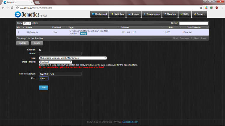
Connecting Gateway to Domoticz@mfalkvidd Right. This is the Domoticz's part of the setting
And I configured Gateway like this:
./configure --my-transport=nrf24 --my-gateway=ethernet --my-controller-ip-address=192.168.1.120make
sudo make installsudo systemctl enable mysgw.service # << adding to boot
sudo systemctl start mysgw.service # << starting -
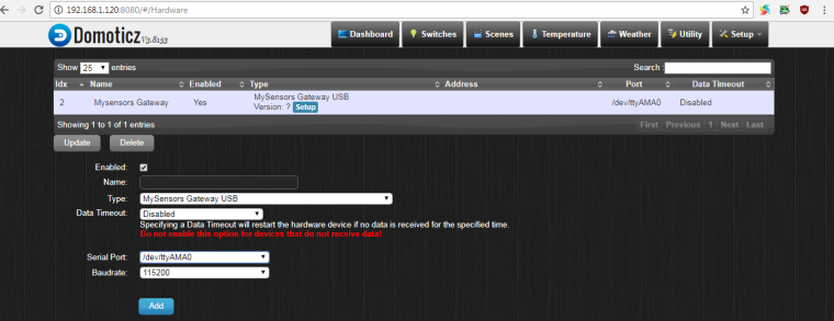
Connecting Gateway to Domoticz@NeverDie There are two serial ports available in Domoticz. Right? And you have to specify which one you are using in Gateway configuration. Right?
-
Connecting Gateway to Domoticz@mfalkvidd It's a good advice, unfortunately it didn't resolve the problem.
-
Connecting Gateway to Domoticz@NeverDie I have no idea.
-
Connecting Gateway to Domoticz@mfalkvidd @NeverDie I tried all sorts of combinations. Like for example:
./configure --my-transport=nrf24
./configure --my-gateway=serial
./configure --my-serial-is-pty
./configure --my-serial-pty=/dev/ttyMySensorsGatewayand in Domoticz MySensors Gateway USB with dev/ttyAMA0
then
./configure --my-transport=nrf24
./configure --my-gateway=ethernet
./configure --my-controller-ip-address=192.168.1.120
and in Domoticz MySensors Gateway with LANI used other different combinations and this is as close to the connection as I could get
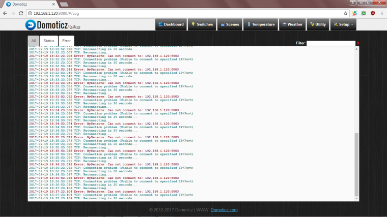
I feel like I'm missing something. -
Connecting Gateway to DomoticzI tried
sudo ./bin/mysgw -dand the Gateway seems to be listening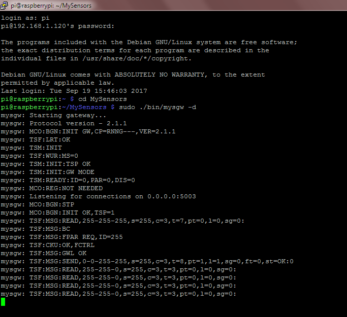
What can I do next? -
Connecting Gateway to DomoticzDecided to switch to Domoticz, ran into problem.
So, Domoticz
and Gateway
https://www.mysensors.org/build/raspberry
got installed.
How does one make them talk to each other? Any help is appreciated. -
Super capacitor charger/balancer with system backup -
How best to find the "best" small solar panel of a particular size?@alexsh1 Manufacturers are probably not very keen on making them, since the production costs are higher.
-
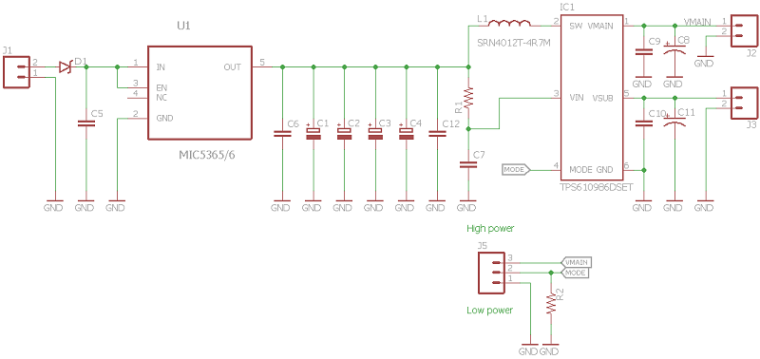
💬 Super-capacitor-power-supply-for-wireless-sensors-w-chargerAdded. MIC5365/6's package is SC-70-5.
-
How best to find the "best" small solar panel of a particular size?@alexsh1 I think they are being discontinued.
-
How best to find the "best" small solar panel of a particular size?Here is a link to openhardware page.
-
How best to find the "best" small solar panel of a particular size?@alexsh1 Normally I use AVX brand.
-
How best to find the "best" small solar panel of a particular size?@alexsh1 Yes, the boost converter works down to 180mV. In other words, it can almost completely discharge capacitors.
-
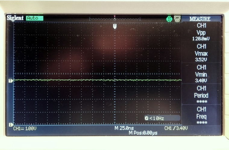
How best to find the "best" small solar panel of a particular size?Noise isn't bad at all. Surprisingly. It is no bigger than the background noise when no input is connected.
-
How best to find the "best" small solar panel of a particular size?A few boards arrived and a couple are assembled
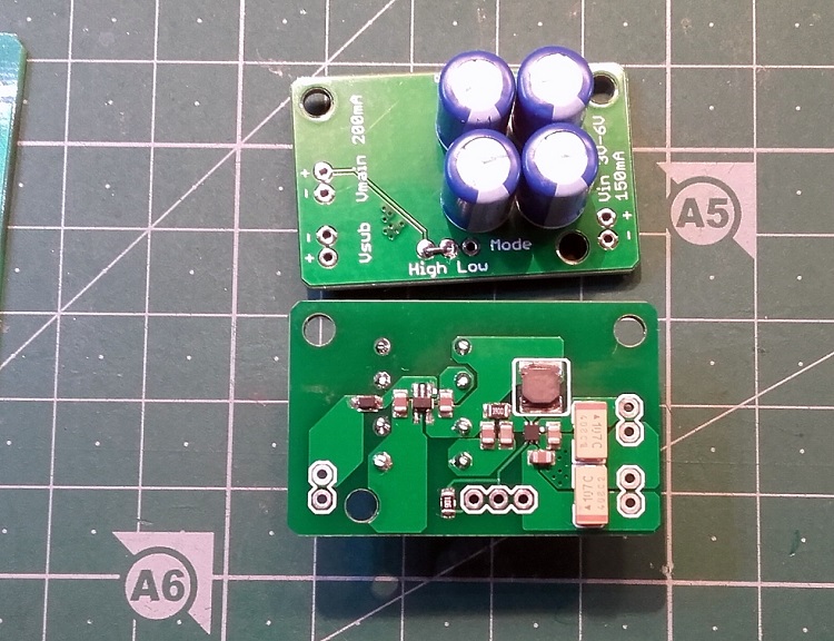
The board charges four 1.5F 2.7V super capacitors. It also provides a boost circuit with 3.45V output on main and sub outputs. It works down to 180mV and provides 3.5mA for 30 minutes. I'll report on leakage.
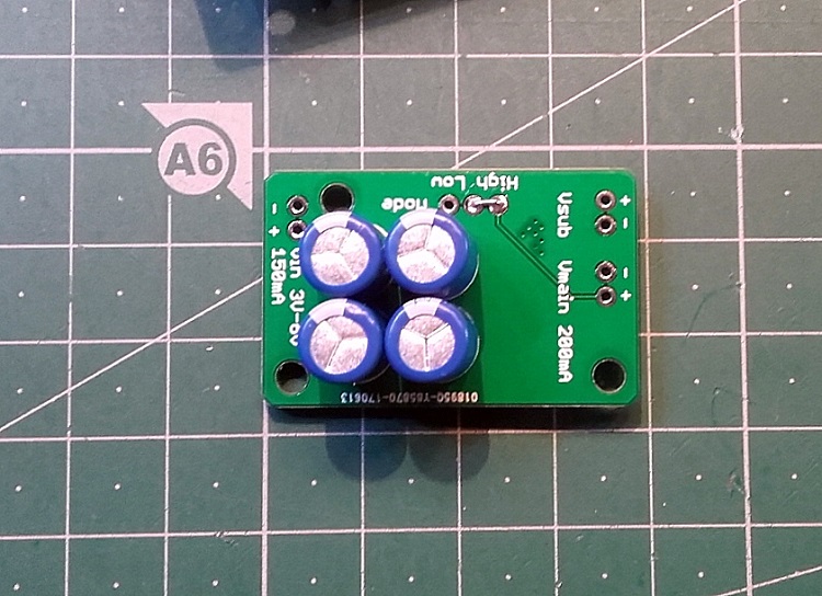
There are two outputs main and sub. Main is on all the time and sub is switched with high signal on the mode connector.
-
MyS not working on solar sensor boardI can't say what's wrong. Can you send it back and I'll take a look at it?