Great Work!
I too am trying something similar- http://forum.mysensors.org/topic/2601/dimmable-led-with-rotary-encoder-example-for-rgb/5. Only my aim is to use the encoder to control full size RGB lighting zones via Home-Assistant and MiLight. Any tips would be greatly appreciated!
H
humblehacker
@humblehacker
Posts
-
5 Channel (RGBWW) LED Dimmer With Rotary Encoder -
Dimmable LED With Rotary Encoder example for RGB?Another MYS RGB Encoder example- http://forum.mysensors.org/topic/1626/5-channel-rgbww-led-dimmer-with-rotary-encoder/3
I might just have enough to work with now:)/*** * This program is free software; you can redistribute it and/or * modify it under the terms of the GNU General Public License * version 2 as published by the Free Software Foundation. * * DESCRIPTION * This sketch provides 4 channels of Dimmable LED Lights using PWM for the MySensors.org project * Inspired by the PWM example sketcy by <henrik.ekblad@gmail.com> and Bruce Lacey. * * REVISION HISTORY * Version 0.1 - Sept 5, 2014 John Soward <soward@soward.net> -- Initial implementation based on example scripts. * Version 0.2 - Sept 7, 2014 -- <soward@soward.net> -- Adjust Timer resolution, neaten up, separate debugging output * Version 0.3 - July 5, 2015 -- <soward@soward.net> Pin changes, use Bounce2, update encoder state when brightness changed via mySensors net * ***/ #define DEBUG 0 #define SN "RGBWW DIM + ENC" #define SV "0.3" #include <Encoder.h> // Using https://www.pjrc.com/teensy/arduino_libraries/Encoder.zip #include <Bounce2.h> #include <MySensor.h> #include <SPI.h> // Ardunio pro mini's have PWM only on 3,5,6,9,10,11 // See http://arduino.cc/en/Main/ArduinoBoardProMini #define RED 3 // Arduino pin attached to MOSFET Gate pin #define GREEN 5 #define BLUE 6 #define WHT 9 #define WHT2 10 //WHT2 is a pure white strip, distinct from the RGBW strip for over stove use // Rotary Encoder connections // Better response if one or both of the encoder triggers is on an interrupt pin #define ENC_SWITCH 8 #define ENC_A 2 #define ENC_B A2 #define ENC_SCALE 2.56 // scaling encoder 256 steps to 100% #define FADE_DELAY 5 // Delay in ms #define FADE_DELAY_FACTOR 16 // MySenor uses pin 9 for CE by default, , can be changed here. // Pin 10 used for CS can also be changed. MySensor gw(4,7); Encoder myEnc(ENC_A, ENC_B); Bounce PowerButton = Bounce(); static int levels[5]; // Current dim levels... MyMessage dimMsgs[5]; MyMessage lightMsgs[5]; int rotValue = 0; // encoder position (for WHT2) int lastBrightness; // last 'on' brightness (for WHT2) void setup() { //Increase Timer frequency to prevent flicker in Pins 5,6 PWM // This alters the performance of millis(), micros() & delay() (basically by 1/16) Unless wiring.c is modified. // See http://playground.arduino.cc/Main/TimerPWMCheatsheet // W/O this change, a low frequency 'beat' or flicker was exhibited when PWM'ing Pin 5 or 6 and another other pin (on Pro Mini 8Mhz clone) TCCR0A = _BV(COM0A1) | _BV(COM0B1) | _BV(WGM00); pinMode(RED,OUTPUT); pinMode(GREEN,OUTPUT); pinMode(BLUE,OUTPUT); pinMode(WHT,OUTPUT); pinMode(WHT2,OUTPUT); pinMode(ENC_SWITCH,INPUT); digitalWrite(ENC_SWITCH,HIGH); PowerButton.attach(ENC_SWITCH); PowerButton.interval(80); // FIXME Mnemonics for the colors/names/locations of the lights could be useful here. for (int i = 0; i < 5; i++) { dimMsgs[i] = MyMessage(i,V_DIMMER); lightMsgs[i] = MyMessage(i,V_LIGHT); levels[i] = 20; } startupDance(); analogWrite(WHT2,0); #ifdef DEBUG Serial.println( SN ); #endif gw.begin( incomingMessage ); // Register each color LED Dimmable Light with the gateway gw.present( 0, S_DIMMER ); gw.present( 1, S_DIMMER ); gw.present( 2, S_DIMMER ); gw.present( 3, S_DIMMER ); gw.present( 4, S_DIMMER ); gw.sendSketchInfo(SN, SV); // Pull the gateway's current dim level - restore light level upon sendor node power-up gw.request( 0, V_DIMMER ); gw.request( 1, V_DIMMER ); gw.request( 2, V_DIMMER ); gw.request( 3, V_DIMMER ); gw.request( 4, V_DIMMER ); } void loop() { // Encoder and button handling. // In this implemenation the Encoder and button control the 2nd White strip, position 4 in the array of strips) // The encoder will brighten/dim the strip from it's current value. // The button will turn off the strip if it is on, or return it to it's last known brightness if it is off bool needsUpdate = false; int newRotValue = myEnc.read(); if (newRotValue != rotValue) { // I guess it really has changed Serial.print("Encoder update:"); Serial.println(newRotValue); if (newRotValue > 255 || newRotValue < 0) { myEnc.write(rotValue); // Enforce max/min } else { rotValue = newRotValue; needsUpdate = true; } } if (PowerButton.update()) { if (!PowerButton.read()) { Serial.println("Button pushed"); Serial.print("lastBrightness: ");Serial.println(lastBrightness); Serial.print("rotValue: ");Serial.println(rotValue); if (rotValue) { // we are on, need to go off lastBrightness = rotValue; rotValue = 0; } else { rotValue = lastBrightness; } myEnc.write(rotValue); needsUpdate = true; } } if (needsUpdate) { int normalizedValue = rotValue / ENC_SCALE; fadeLEDToLevel(4,normalizedValue,0); gw.send(dimMsgs[4].set(normalizedValue)); gw.send(lightMsgs[4].set(normalizedValue > 0 ? 1 : 0)); } // Standard mySensors message processing (no sleep) gw.process(); } void incomingMessage(const MyMessage &message) { if (message.type == V_LIGHT || message.type == V_DIMMER) { // Retrieve the power or dim level from the incoming request message int requestedLevel = atoi( message.data ); // Adjust incoming level if this is a V_LIGHT variable update [0 == off, 1 == on] requestedLevel *= ( message.type == V_LIGHT ? 100 : 1 ); // Clip incoming level to valid range of 0 to 100 requestedLevel = requestedLevel > 100 ? 100 : requestedLevel; requestedLevel = requestedLevel < 0 ? 0 : requestedLevel; #ifdef DEBUG Serial.print( "On child id "); Serial.print(message.sensor); Serial.print( " Changing level to " ); Serial.print( requestedLevel ); Serial.print( ", from " ); Serial.println( levels[message.sensor]); #endif fadeLEDToLevel( message.sensor,requestedLevel,FADE_DELAY*FADE_DELAY_FACTOR ); // Sensor 4 is the strip attached the the encoder, update the encoders value, using the scaling factor // FIXME Mnemonics might make this more readable/extensible. if (message.sensor == 4) { myEnc.write(requestedLevel*ENC_SCALE); } // Inform the gateway of the current DimmableLED's SwitchPower1 and LoadLevelStatus value... gw.send(lightMsgs[message.sensor].set(levels[message.sensor] > 0 ? 1 : 0)); // hek comment: Is this really nessesary? // soward: Probably not, unless there exists some reason why the requested value does not equal // the set value gw.send( dimMsgs[message.sensor].set(levels[message.sensor]) ); } } void startupDance() { int i,j; // Bring each color up and down independently for (i=0;i<5;i++) { fadeLEDToLevel(i,100,1); delay(50*FADE_DELAY_FACTOR); fadeLEDToLevel(i,0,1); } //Bringing each color up sequentially, then back down to 2 for (i=0;i<5;i++) { fadeLEDToLevel(i,100,1); } delay(50*FADE_DELAY_FACTOR); for (i=0;i<5;i++) { fadeLEDToLevel(i,2,1); } } // Helper function to map controller pins to names for strips int pinForID(int ledID) { switch (ledID) { case 0: return RED; case 1: return GREEN; case 2: return BLUE; case 3: return WHT; case 4: return WHT2; return 0; // Default to Red } } /*** * This method provides a graceful fade up/down effect */ void fadeLEDToLevel( int theLED, int toLevel, int wait ) { int delta = ( toLevel - levels[theLED] ) < 0 ? -1 : 1; while ( levels[theLED] != toLevel ) { levels[theLED] += delta; analogWrite( pinForID(theLED), (int)(levels[theLED] / 100. * 255) ); delay( wait ); } } 7 POSTS 1.1k VIEWS Reply -
Arduino IDE Library ManagerThat's an interesting approach! I also maintain my Arduino Sketchbook using Git. In fact, I even created a little tutorial about it on- https://www.hackster.io/humblehacker/cloud-based-arduino-development-workflow-using-github-8f9d77?ref=user&ref_id=3916&offset=2
Are you on Hackster.io? If so would you mind reposting the above mentioned steps to the tutorial comments? I think it would add a whole new dimension to the concept of sketchbook management using git... -
Dimmable LED With Rotary Encoder example for RGB?There's also the following sketch for controlling an RGB LED strip from PiDome-
// Example sketch showing how to control an RGB Led Strip. // This example will not remember the last rgb color set after power failure. #include <MySensor.h> #include <SPI.h> #define RED 3 // Arduino PWM pin for Red #define GREEN 5 // Arduino PWM pin for Green #define BLUE 6 // Arduino PWM pin for Blue #define node 1 // Assigning the node (this will be the address for Pidome) #define strip 1 // sensor number needed in the custom devices set up int RGB_pins[3] = {RED,GREEN,BLUE}; long RGB_values[3] = {0,0,0}; MySensor gw; void setup() { // Initialize library and add callback for incoming messages gw.begin(incomingMessage, node, true); // Send the sketch version information to the gateway and Controller gw.sendSketchInfo("RGB Node", "1.0"); // Register the sensor to gw gw.present(strip, S_CUSTOM); // Set the rgb pins in output mode for (int i = 0; i<3; i++) { pinMode(RGB_pins[i], OUTPUT); } } void loop() { // Alway process incoming messages whenever possible gw.process(); } void incomingMessage(const MyMessage &message) { // We only expect one type of message from controller. But we better check anyway. if (message.type==V_VAR1) { // starting to process the hex code String hexstring = message.getString(); //here goes the hex color code coming from Pidome through MySensors (like FF9A00) long number = (long) strtol( &hexstring[0], NULL, 16); RGB_values[0] = number >> 16; RGB_values[1] = number >> 8 & 0xFF; RGB_values[2] = number & 0xFF; for (int i = 0; i<3; i++) { analogWrite(RGB_pins[i],RGB_values[i]); } // Write some debug info Serial.print("Red is " ); Serial.println(RGB_values[0]); Serial.print("Green is " ); Serial.println(RGB_values[1]); Serial.print("Blue is " ); Serial.println(RGB_values[2]); //if you want to convert it again from rgb to hex long rgb = 0; rgb = ((long)RGB_values[0] << 16) | ((long)RGB_values[1] << 8 ) | (long)RGB_values[2]; Serial.print("This is the reconverted HEX value: #" ); Serial.println(String(rgb, HEX)); } }``` -
Dimmable LED With Rotary Encoder example for RGB?For reference- This is the code for the DIMMABLELIGHTWITHROTARYENCODER example in the MYS Library-
/** * The MySensors Arduino library handles the wireless radio link and protocol * between your home built sensors/actuators and HA controller of choice. * The sensors forms a self healing radio network with optional repeaters. Each * repeater and gateway builds a routing tables in EEPROM which keeps track of the * network topology allowing messages to be routed to nodes. * * Created by Henrik Ekblad <henrik.ekblad@mysensors.org> * Copyright (C) 2013-2015 Sensnology AB * Full contributor list: https://github.com/mysensors/Arduino/graphs/contributors * * Documentation: http://www.mysensors.org * Support Forum: http://forum.mysensors.org * * This program is free software; you can redistribute it and/or * modify it under the terms of the GNU General Public License * version 2 as published by the Free Software Foundation. * ******************************* * * REVISION HISTORY * Version 1.0 - Developed by Bruce Lacey and GizMoCuz (Domoticz) * Version 1.1 - Modified by hek to incorporate a rotary encode to adjust * light level locally at node * * DESCRIPTION * This sketch provides an example how to implement a dimmable led light node with a rotary * encoder connected for adjusting light level. * The encoder has a click button which turns on/off the light (and remembers last dim-level) * The sketch fades the light (non-blocking) to the desired level. * * Default MOSFET pin is 3 * * Arduino Encoder module * --------------------------- * 5V 5V (+) * GND GND (-) * 4 CLK (or putput 1) * 5 DT (or output 1) * 6 SW (Switch/Click) */ #include <SPI.h> #include <Encoder.h> #include <MySensor.h> #include <Bounce2.h> #define LED_PIN 3 // Arduino pin attached to MOSFET Gate pin #define KNOB_ENC_PIN_1 4 // Rotary encoder input pin 1 #define KNOB_ENC_PIN_2 5 // Rotary encoder input pin 2 #define KNOB_BUTTON_PIN 6 // Rotary encoder button pin #define FADE_DELAY 10 // Delay in ms for each percentage fade up/down (10ms = 1s full-range dim) #define SEND_THROTTLE_DELAY 400 // Number of milliseconds before sending after user stops turning knob #define SN "DimmableLED /w button" #define SV "1.2" #define CHILD_ID_LIGHT 1 #define EEPROM_DIM_LEVEL_LAST 1 #define EEPROM_DIM_LEVEL_SAVE 2 #define LIGHT_OFF 0 #define LIGHT_ON 1 int dimValue; int fadeTo; int fadeDelta; byte oldButtonVal; bool changedByKnob=false; bool sendDimValue=false; unsigned long lastFadeStep; unsigned long sendDimTimeout; char convBuffer[10]; MySensor gw; MyMessage dimmerMsg(CHILD_ID_LIGHT, V_DIMMER); Encoder knob(KNOB_ENC_PIN_1, KNOB_ENC_PIN_2); Bounce debouncer = Bounce(); void setup() { // Set knob button pin as input (with debounce) pinMode(KNOB_BUTTON_PIN, INPUT); digitalWrite(KNOB_BUTTON_PIN, HIGH); debouncer.attach(KNOB_BUTTON_PIN); debouncer.interval(5); oldButtonVal = debouncer.read(); // Set analog led pin to off analogWrite( LED_PIN, 0); // Init mysensors library gw.begin(incomingMessage, AUTO, false); // Send the Sketch Version Information to the Gateway gw.present(CHILD_ID_LIGHT, S_DIMMER); gw.sendSketchInfo(SN, SV); // Retreive our last dim levels from the eprom fadeTo = dimValue = 0; byte oldLevel = loadLevelState(EEPROM_DIM_LEVEL_LAST); Serial.print("Sending in last known light level to controller: "); Serial.println(oldLevel); gw.send(dimmerMsg.set(oldLevel), true); Serial.println("Ready to receive messages..."); } void loop() { // Process incoming messages (like config and light state from controller) gw.process(); // Check if someone turned the rotary encode checkRotaryEncoder(); // Check if someone has pressed the knob button checkButtonClick(); // Fade light to new dim value fadeStep(); } void incomingMessage(const MyMessage &message) { if (message.type == V_LIGHT) { // Incoming on/off command sent from controller ("1" or "0") int lightState = message.getString()[0] == '1'; int newLevel = 0; if (lightState==LIGHT_ON) { // Pick up last saved dimmer level from the eeprom newLevel = loadLevelState(EEPROM_DIM_LEVEL_SAVE); } // Send dimmer level back to controller with ack enabled gw.send(dimmerMsg.set(newLevel), true); // We do not change any levels here until ack comes back from gateway return; } else if (message.type == V_DIMMER) { // Incoming dim-level command sent from controller (or ack message) fadeTo = atoi(message.getString(convBuffer)); // Save received dim value to eeprom (unless turned off). Will be // retreived when a on command comes in if (fadeTo != 0) saveLevelState(EEPROM_DIM_LEVEL_SAVE, fadeTo); } saveLevelState(EEPROM_DIM_LEVEL_LAST, fadeTo); Serial.print("New light level received: "); Serial.println(fadeTo); if (!changedByKnob) knob.write(fadeTo); // Cancel send if user turns knob while message comes in changedByKnob = false; sendDimValue = false; // Stard fading to new light level startFade(); } void checkRotaryEncoder() { long encoderValue = knob.read(); if (encoderValue > 100) { encoderValue = 100; knob.write(100); } else if (encoderValue < 0) { encoderValue = 0; knob.write(0); } if (encoderValue != fadeTo) { fadeTo = encoderValue; changedByKnob = true; startFade(); } } void checkButtonClick() { debouncer.update(); byte buttonVal = debouncer.read(); byte newLevel = 0; if (buttonVal != oldButtonVal && buttonVal == LOW) { if (dimValue==0) { // Turn on light. Set the level to last saved dim value int saved = loadLevelState(EEPROM_DIM_LEVEL_SAVE); newLevel = saved > 0 ? saved : 100; } gw.send(dimmerMsg.set(newLevel),true); } oldButtonVal = buttonVal; } void startFade() { fadeDelta = ( fadeTo - dimValue ) < 0 ? -1 : 1; lastFadeStep = millis(); } // This method provides a graceful none-blocking fade up/down effect void fadeStep() { unsigned long currentTime = millis(); if ( dimValue != fadeTo && currentTime > lastFadeStep + FADE_DELAY) { dimValue += fadeDelta; analogWrite( LED_PIN, (int)(dimValue / 100. * 255) ); lastFadeStep = currentTime; Serial.print("Fading level: "); Serial.println(dimValue); if (fadeTo == dimValue && changedByKnob) { sendDimValue = true; sendDimTimeout = currentTime; } } // Wait a few millisecs before sending in new value (if user still turns the knob) if (sendDimValue && currentTime > sendDimTimeout + SEND_THROTTLE_DELAY) { // We're done fading.. send in new dim-value to controller. // Send in new dim value with ack (will be picked up in incomingMessage) gw.send(dimmerMsg.set(dimValue), true); // Send new dimmer value and request ack back sendDimValue = false; } } // Make sure only to store/fetch values in the range 0-100 from eeprom int loadLevelState(byte pos) { return min(max(gw.loadState(pos),0),100); } void saveLevelState(byte pos, byte data) { gw.saveState(pos,min(max(data,0),100)); } -
Arduino IDE Library ManagerIs there a recommended method for managing library conflicts in the meantime? Or do we have to use two separate versions of the Arduino IDE?
-
Arduino IDE Library ManagerHello,
My apologies if this subject has already been addressed but I have tried to search the help forums and nothing has turned up. I'm sure plenty users are aware that as of Arduino v1.6.2 the recommended method for installing new libraries is to use the Library Manager feature. Thus far, the feature has been a handy way of making sure various libraries are kept up-to-date while minimizing compatibility issues.
As far as I can tell, MySensors is still recommending users install the MYS library using the legacy method, which seems to cause some confusion with the current method for tracking changes within supported libraries in the manager. For example, the IDE seems to only recognize the default version of the Dallas Temperature library instead of the custom version bundled with MYS. This results in compile errors and I can't seem to simply replace the old library without updating through the manager... Is there any reason why MySensors needs to be installed using the legacy method? Are there any efforts underway to make it more compatible with the Arduino IDE. If not, how can we avoid conflicts without having to disable either the library manager or MySensors? -
Dimmable LED With Rotary Encoder example for RGB?Does the rgb LED in the rotary knob react automatically to the knob turning or does it respond to software direction for color change?
AFAIK the embedded RGB LED must be programmed like any other LED, which makes it much more complicated to augment the colors with the addition of something like a Neopixel ring. As of the present I've been able to control the embedded LED colors using this sketch but have yet to attempt any further modifications until I settle on how I want to actually handle communicating with the remote server. I'm most likely going to be using Home-Assistant to handle the overall automations so any communications will need to be a supported HASS component. As a result, I have been attempting to build the sketch around the MQTT protocol but this may prove more complicated than its worth. However, if I'm able to successfully modify the original MySensors example, then much of the hard work will have already be prepared in the MYS API...
I could envision turning the knob to desired color per the rgb LED, push to set color (send to controller) which would also toggle the knob function to a dimmer control, possibly by using the LED brightness (without color change) as feedback and pushing the knob to set dim state and toggle back knob function to color control.
If I am able to use the original example as my template, then your suggestion might be much easier to incorporate since the the dimmer component already exists without modification. The task therefore is to figure out which elements within the original sketch can be modified to trigger RGB events. This of course requires a certain familiarity with the MySensors framework for which I must confess a certain ignorance. So again, if others are more familiar with MYS have any suggestions while I'm catching up on the docs, please do speak up and I'll be sure to credit your participation.
Besides writing the actual source code, much work remains on the Home-Assistant end to ensure proper integration. As of the present, MySensors support officially only extends to raw analog sensor data via the serial gateway. Additionally, as of Home-Assistant version 0.10, raw sensor data now requires the use of a new templating engine. Some progress has also been made in incorporating the experimental MQTTClientGateway to HA. Both developments are likely positive indications as I could envision MySensors support would be enhanced greatly with a community curated template and MQTT support.
-
Dimmable LED With Rotary Encoder example for RGB?Hello,
I'm trying to modify the "Dimmable LED With Rotary Encoder" example to use as an RGB LED actuator rather than a dimmer. The key for making this work however is the Illuminated RGB Rotary Encoder from Sparkfun which conveniently includes an RGB LED inside the knob itself.
The goal is to be able to find a desired color by twisting the knob and to select it with the pushbutton. The color values will then be transmitted to a controller which in turn signals the RGB Light Bulbs (e.g HUE,LIFX, LimitlessLED) to reflect the chosen color.
I had originally planned to use a simple trim pot with a Neopixel Ring and an ESP8266 transmitting via MQTT, but the RGB Rotary Encoder seemed to simplify matters considerably. I should've guessed that nothing ever ends up being that easy as it turns out no two people seem to agree on a standard approach to programming rotary encoders with Arduino... Some say you need to use interrupts, others insist on adding resistors or capacitors... Luckily my research led me full circle back to MySensors where the DimmableLED sketch ALMOST accomplishes my goal... But not quite...
If others have had experience with either the DimmableLEDRotaryEncoder example and/or the RGB Encoder from Sparkfun, I would greatly appreciate suggestions.
When I'm able to complete a proof of concept I'm planning to author a detailed tutorial on hackster.io, and I'll be sure to credit anyone who helps!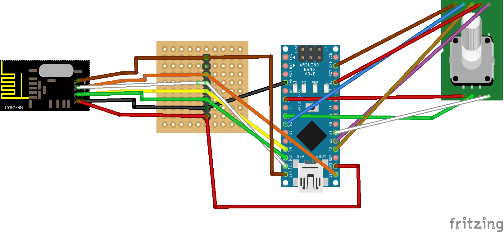
-
Home Assistant - How to recognize MySensors nodesNever mind then... As long as your using Mosquitto as your broker and the MQTT CLIENT Gateway (from the development branch) rather than the default MQTT Gateway sketch from- http://www.mysensors.org/build/mqtt_gateway then none of my earlier comments should apply... Basically I was saying that the default MYSensors MQTT Gateway is set up to function as a broker and would therefore conflict with any Mosquitto server running on the same port. The MQTT CLIENT Gateway (emphasis on CLIENT) from the development branch isnt set up as a broker so it shouldnt conflict with a Mosquitto installation.
-
Home Assistant - How to recognize MySensors nodes@martinhjelmare said:
FYI, my fifo_queue pull request has been merged with dev branch at pymysensors, so I'm hoping to be able to implement switch support for the mysensors component in homeassistant very soon.
Thats great news! That should be a huge help with my plans for building an RGB Lighting controller based on the rotary_led_dimmer sketch! If I can ever figure out how to implement a simple toggle switch first...
-
Home Assistant - How to recognize MySensors nodesFor the time being, I'm thinking of taking a different approach with my toggle switch... I'm thinking of simply defining the button output as a binary sensor which can then toggle between two predefined scenes. At least in my case, input only needs to go in one direction so there's no need to receive any data from the controller....
-
Home Assistant - How to recognize MySensors nodes@drock1985 said:
I've been trying to get MQTT working using the Dev branch here (http://forum.mysensors.org/topic/2352/guide-setting-up-and-testing-mqtt-client-gateway/) and have my configuration.yaml file looking like this for my W5100MQTT broker:
#MySensors MQTT Test
mqtt 1:
  broker: 192.168.86.198
  port: 1883
#  client_id: home-assistant-1
  keepalive: 60
#  username: USERNAME
#  password: PASSWORD
Does anyone have any ideas? @humblehacker @martinhjelmare @hek ?
Does the IP address you defined in the config.yaml point to your Mosquitto Broker or the Arduino-Ethernet Shield? If it points to the Arduino afaik the point of the MQTTCLIENT Gateway is that it can be run as a client if you've already got a Mosquitto broker. Otherwise you would either need to remove mosquitto or forward it to a different port than the default 1883. If this was the case then HASS would be looking for a broker where none exists which is why it is missing configuration items...
-
Home Assistant - How to recognize MySensors nodes@drock1985
It looks like we're trying to do similar things with HA and MYS... I've been working on a rotary encoder switch for colored lights (eg Limitlessled/HUE etc...) and had been trying to program it through MQTT. However, I just now noticed the LEDDIMMERwithROTARYENCODER sketch in the MySensors examples so I thought I might try using MYS instead of MQTT. Of course that leads right back to the lack of support for MYS Switches in HASS... Perhaps there's a solution for both of our problems if we use an MQTT Gateway instead? I've worked with MQTT and NodeRED before and it was pretty straight forward, but then again I've been having a much harder time understanding the way its implemented in HASS... So I might need to work with it some more before I can be of any help testing the MQTT MYS Gateway with HA... -
Arduino Yun, Linino, OpenWRTI remember when the Yun first came out, everybody seemed to be using the Raspberry Pi as a microcontroller through its GPIO pins... Now with the ESP8266, we have a device which was originally designed to function like an RF module with wifi capabilities, being pushed into a role it wasn't designed for. As a major advoc ate of affordability, I see much to love in the ESP8266... Yet I still can't shake the thought that the Linino-Yun approach still makes the most efficient use of a CPU and MPU together.
If the ESP popularity has one important lesson however its that affordability can outweigh accessibility and capability. And unfortunately, at $70, its looking like the Yun is becoming the LEAST affordable IOT option... I wonder if there are more cost-effective means of deploying the Bridge Library and Linino/OpenWRT? The closest I have yet found are the Dragino HE Modules which at $21 each, are still pretty pricy for a bare surface mount component. My original idea was to make a custom Yun by mounting an HE Module with a Pro Micro. This would probably require a custom breakout design however. I did notice a new OpenWRT dev board called the WRTnode. While it also uses a MIPS CPU the WRTnode is based on an MTKMT7620N chipset instead of the AR9331... I wonder if Linino or the Bridge Library would run on this alternate chip? -
Home Assistant - How to recognize MySensors nodes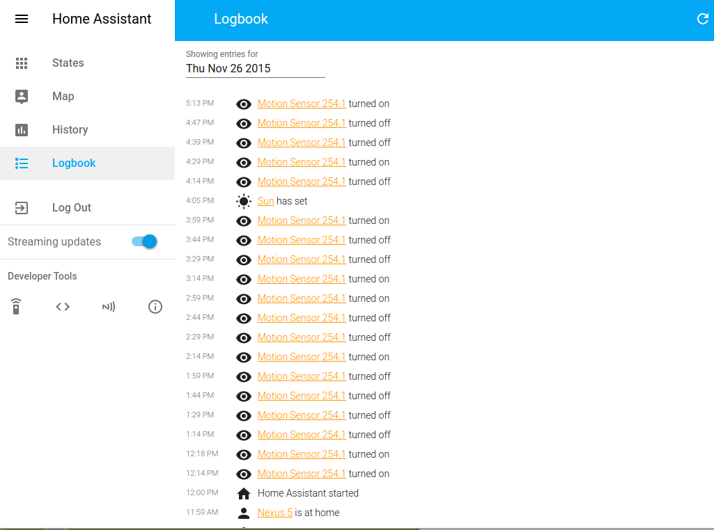
:smiley:
Other than the fact that my log seems to think its yesterday... I just need to find out why I can't use MySensors with Any ATMega32u4 devices... Attiny85/Trinket support would be nice too but I dont need to push my luck... -
ATtiny supported?I think Attiny85, especially in the form of the Adafruit Trinket/Flora 3.3v version would be a perfect match for MySensors! Especially now that the Arduino Boards Manager makes third party boards much easier to work with. How is the Attiny MYS fork coming along?
-
Home Assistant - How to recognize MySensors nodesSure enough-
WARNING:mysensors.mysensors:Error decoding message from gateway, probably received bad byte.@martinhjelmare- How do I create a new gateway instance? Simply restart?
-
Home Assistant - How to recognize MySensors nodesUPDATE:
YES!!! The Uno connected to the motion sensor is transmitting data to my Arduino Nano gateway and I can finally see the data on the serial monitor! Now I just need to reconnect the gateway to Home Assistant to see what it picks up.
Lesson learned as of the present is to only use ATMega328 processors like the Uno, Nano, Pro Mini etc... Most of my controllers at this point are based on the 32u4 so it would be good if we could figure out why the Leo boards don't work with MYS... Has anybody else experienced this problem? -
Home Assistant - How to recognize MySensors nodes@martinhjelmare said:
Yes, it should be enabled by default, that's why I didn't mention it in my first advice. But it's good to double check anyway.
Are you sure you have two different instances of the Arduino IDE running when you test? Only one serial monitor can be active at a time, per IDE. It's not enough to open a second sketch window. You have to start the IDE twice from the start menu, or however you start it. Also, check the ports. You should see different headings in the serial monitor window, specifying the port.
What hardware are you using?
I had replied to this a couple days ago but it must not have posted so I apologize for the tardy response...
I think I might've narrowed down to what my problem is but first I'll reply to your question. My first test used two different instances of the IDE running on two different systems.
The gateway controller sketch was compiled on Windows 10 w/Arduino 1.6.6 and ran successfully on an Arduino UNO. The sensor/sender sketch was compiled on my Ubuntu MATE 15.10 laptop with Arduino 1.6.6 on an Arduino Leonardo.Interestingly, I just tried swapping out the hardware so the Uno connected to Linux and the Leo connected to Windows. Sure enough, the Uno works as expected running both the sensor and the gateway sketch on Linux and Windows while the Leo won't work with any MySensors sketch on either Linux or Windows... So the problem may be related to the serial port on the ATMega32u4. As I mentioned earlier, I was able to get the Leo to work with the standard RF24 library, so it must be something about the Mysensors library that doesn't get along with the ATMega32u4 processors...
I'll try running my Arduino Nano now to see if it works with signals sent from my Uno.