Perhaps it would be good to update the example code. I mean the pull-up sequence:
"It is recommended to set the pinMode() to INPUT_PULLUP to enable the internal pull-up resistor." - https://www.arduino.cc/reference/en/language/functions/digital-io/digitalwrite/
The following seems to be obsolete:
// Setup the button
pinMode(BUTTON_PIN,INPUT);
// Activate internal pull-up
digitalWrite(BUTTON_PIN,HIGH);
I
iahim67
@iahim67
Posts
-
💬 Door, Window and Push-button Sensor -
Arduino ProMini 3.3V on 1MHz + RFM69W missing ACKsHi, as a side note - check the datasheet of the 100uf capacitor you have used for the leakage current as it could be as high a few uA which is comparable with the current of a sleeping ATMega328 / Arduino board. Make sure you use a low leakage capacitor for a longer battery life.
For a low current temperature sensor you can use a thermistor (like 4k7 @ 25 Celsius) in series with a resistor (4k7 1%). Connect one end of the th to the GND, one end of the resistor to a digital output of the Arduino and the common connection of the th and resistor to an analog input of Arduino. You will power on (make the output HIGH) the th+resistor string from the digital out shortly before making the measurement then make the output LOW after the measurement.
Means you will only use power to measure the temperature for a very short time.
Here is my code (I am not a professional firmware guy :smiley: ) for such a temperature sensor:// ver. v1.2 /* Mini v5 TH: Th=GND, Series Resistor=3, Middle=A0 check Radio connections/wires check power supply +5V */ //Enable debug prints to serial monitor //#define MY_DEBUG #define MY_RADIO_NRF24 #define MY_NODE_ID 9 #define DEBUG 0 #define BATTERY_SENSOR 1 #include <MySensors.h> #include <Vcc.h> #define TH_LIBRARY_CHILD_ID 1 #define VOLTAGE_CHILD_ID 2 #define TH_PIN 3 int _nominal_resistor = 4700; int _nominal_temperature = 25; int _b_coefficient = 3950; int _series_resistor = 4877; int _pin = 0; int batt_report_count = 120; const float VccMin = 1.8; const float VccMax = 3.0; const float VccCorrection = 1.0 / 1.0; // Measured Vcc by multimeter divided by reported Vcc Vcc vcc(VccCorrection); MyMessage msgTemp(TH_LIBRARY_CHILD_ID, V_TEMP); MyMessage msgVoltage(VOLTAGE_CHILD_ID, V_VOLTAGE); void setup() { //Serial.begin(115200); } void presentation() { // Send the sketch version information to the gateway and Controller sendSketchInfo("TH_LIBRARY@Mini_2xR6", "1.2_FOTA"); wait(1); present(TH_LIBRARY_CHILD_ID, S_TEMP, "TH_LIBRARY"); wait(1); present(VOLTAGE_CHILD_ID, S_MULTIMETER, "TH_LIBRARY_BATT"); wait(1); } void loop() { if (batt_report_count == 120) { batteryReport(); } batt_report_count--; if (batt_report_count == 0) { batt_report_count = 120; } tempReport(); smartSleep(180000); } //############################################################### // Send a battery level report to the controller void batteryReport() { // measure the board vcc float v = vcc.Read_Volts(); float p = vcc.Read_Perc(VccMin, VccMax); #if DEBUG Serial.print("VCC = "); Serial.print(v); Serial.println(" Volts"); Serial.print("VCC = "); Serial.print(p); Serial.println(" %"); #endif #if BATTERY_SENSOR // report battery voltage send(msgVoltage.set(v, 3)); wait(1); #endif // report battery level percentage sendBatteryLevel(p); wait(1); } //################################################################## void tempReport() { // set TH pin in output mode pinMode(TH_PIN, OUTPUT); // set TH_PIN HIGH digitalWrite(TH_PIN, HIGH); wait(1); // read the voltage across the thermistor float adc = analogRead(_pin); // set TH_PIN LOW digitalWrite(TH_PIN, LOW); // calculate the temperature float reading = (1023 / adc) - 1; reading = _series_resistor / reading; float temperature; temperature = reading / _nominal_resistor; // (R/Ro) temperature = log(temperature); // ln(R/Ro) temperature /= _b_coefficient; // 1/B * ln(R/Ro) temperature += 1.0 / (_nominal_temperature + 273.15); // + (1/To) temperature = 1.0 / temperature; // Invert temperature -= 273.15; // convert to C #if DEBUG == 1 Serial.print(F("THER I=")); Serial.print(TH1_CHILD_ID); Serial.print(F(" V=")); Serial.print(adc); Serial.print(F(" T=")); Serial.println(temperature); #endif send(msgTemp.set(temperature, 1)); wait(1); } -
How to send serial commands (v_var) from Domoticz to serial gateway@Inso - you can eventually register a few TEXT devices with one of your Arduino sensors, like:
present(LCD_LINE1_CHILD_ID, S_INFO, LCD_LINE1);then periodically ask data back from Domoticz like:
  if (!line1received) {
    request(LCD_LINE1_CHILD_ID, V_TEXT);
#if DEBUG == 1
    Serial.println("Requested line1 from gw !");
#endif
    wait(5000, 2, V_TEXT); // wait for 5s or until a message of type V_TEXT is received
  }
just define this first:
bool line1received = false;For more details on the DzVents (2.4x) side have a look in the Domoticz installation folder, there are a few good DzVents examples, this is the path in Windows7:
C:\Program Files (x86)\Domoticz\scripts\dzVents\examplesHope it helps ...
-
low voltage temperature sensor in tht package@rozpruwacz - one more thing you can do is to place a small ceramic capacitor (like 1nF to 10nF ... or just experiment with other values) in parallel to the thermistor, that will also filter noise.
-
low voltage temperature sensor in tht package@Nca78 - good to know, thanks!
@rozpruwacz - having a 4K7 thermistor at the end of a few meters of cable is OK ... unless the cable is an inch away from a power motor, fluorescent light, etc. Does not matter much what type of cable you use if you keep it short (a couple of meters).
Don't use large value thermistors like 1Meg.
Try to use twisted cable to connect the thermistor to Arduino if shielded is not an option, twisted cables can reduce some type of interference and noise.
These things may help you ... hopefully:smile: -
low voltage temperature sensor in tht package@rozpruwacz, have you considered a simple and cheap thermistor? If you need temperature measurement and nothing else then a thermistor in series with a resistor (connected to an Arduino output pin) works at any voltage and is very fast - means Arduino will spend more time sleeping. It will be the Arduino itself limiting the lower threshold of you voltage supply.
If you burn a 1MHz internal oscillator boot-loader you can use your rechargeable or non-rechargeable batteries down to 1.8V as you can see in the ATMega328P datasheet: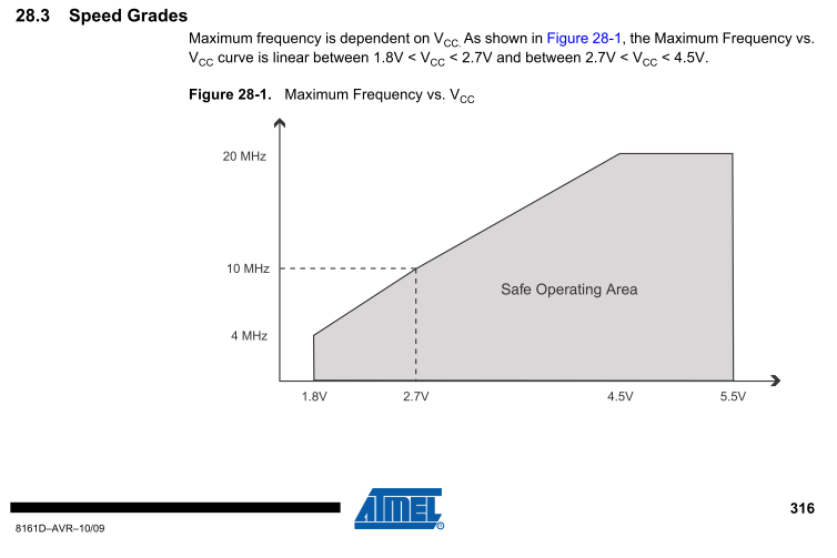
It may require more investigation however - I read on this forum that MySensors gives random faults when Arduino is running @ 1MHz internal oscillator!?
It would be useful if someone could validate / invalidate the issue or share experience about running @ 1MHz internal oscillator ... -
MySensors - Get Temperature value from another node through the Gateway@Joe13, I am new to DzVents too ... but it is a great opportunity to learn:smile:
Have a look into the Domoticz installation folder, can't remember now exactly where but there is a sub-folder with interesting examples, when you start reading these examples you may have a better overall understanding of how DzVents works.
Their wiki is also very usefull:
https://www.domoticz.com/wiki/DzVents:_next_generation_LUA_scripting
Have fun @Joe13 ... -
MySensors - Get Temperature value from another node through the GatewayHi @Joe13, I managed to request information from the Domoticz controller and put it on a LCD (LCD2004A in my case). My Arduino code below, not very polished nor optimized as I am not a programmer :smile: but it works nicely so far. This code running on the Arduino Nano will create 4 text devices on the Domoticz side: LCD1_LINE1, LCD1_LINE2, LCD1_LINE3 and LCD1_LINE4 then it will display what ever Domoticz will put (change) in these text devices. At the end of the Arduino sketch there is a DzVents code that will count both Mysensors devices (except text devices) and Domoticz devices (all) and will place this information in the text device LCD1_LINE3 which will be displayed on my LCD accordingly - on the third line. You can create DzVents (or LUA) code that will place in these text devices virtually anything available in Domoticz, temperature included of course.
Second DzVents code at the end of my Arduino code will display on the first line on my LCD the temperature set on a virtual TERMOSTAT device and the current temperature measured with a cheap thermistor on the same node as the LCD device.
Comment this line if you use the default radion channel: #define MY_RF24_CHANNEL 83
Hope it helps .../* LCD2004A 20x4 - LCD pin 1 --> GND - LCD pin 2 --> +5V - LCD pin 3 --> (1K - 10K) POTI - LCD pin 5 --> GND - LCD pin 15 --> to +5V in series with 100 OHM (Backlight "+") - LCD pin 16 --> GND (Backlight "-") - LCD function: RS, E, D4, D5, D6, D7 - LCD2004A pins: 4 , 6 ,11 ,12, 13, 14 - NANO pins: 3, 4, 5, 6, 7, 8 Thermistor: 4K7 / B57164K0472J000 in series with 4K7 resistor TH pin1 to GND TH pin2 to pin2 of the series resistor and together to A0 on the Arduino side Series resistor pin1 to +5V _nominal_resistor adjusted to 4660 (compared to Fluke TK80 thermocouple module + Fluke 87 multimeter) to get the same temperature as the Fluke thermocouple @ around 25 Celsius - each Thermistor requires individual "calibration" */ // Enable debug prints to serial monitor //#define MY_DEBUG #define MY_RADIO_NRF24 #define MY_NODE_ID 240 // Enable repeater functionality for this node #define MY_REPEATER_FEATURE #define MY_RF24_CHANNEL 83 #define DEBUG 1 #include <MySensors.h> // Node specific #define SKETCH_NAME "LCD2004A_1_Nano" #define SKETCH_VERSION "1.0_2.2.0" #define SENSOR_DESCRIPTION "LCD1_MySensors" #define LCD_TH "LCD1_TH" #define LCD_LINE1 "LCD1_LINE1" #define LCD_LINE2 "LCD1_LINE2" #define LCD_LINE3 "LCD1_LINE3" #define LCD_LINE4 "LCD1_LINE4" #define LCD_TH_CHILD_ID 241 #define LCD_LINE1_CHILD_ID 242 #define LCD_LINE2_CHILD_ID 243 #define LCD_LINE3_CHILD_ID 244 #define LCD_LINE4_CHILD_ID 245 // Node specific #include "LiquidCrystal.h" LiquidCrystal lcd(3, 4, 5, 6, 7, 8); int _nominal_resistor = 4660; int _nominal_temperature = 25; int _b_coefficient = 3950; int _series_resistor = 4697; int _pin = 0; String line1 = "line1 "; String line2 = "line2 "; String line3 = "line3 "; String line4 = "line4 "; bool line1received = false; bool line2received = false; bool line3received = false; bool line4received = false; MyMessage msgTemp(LCD_TH_CHILD_ID, V_TEMP); MyMessage msgLine1(LCD_LINE1_CHILD_ID, V_TEXT); MyMessage msgLine2(LCD_LINE2_CHILD_ID, V_TEXT); MyMessage msgLine3(LCD_LINE3_CHILD_ID, V_TEXT); MyMessage msgLine4(LCD_LINE1_CHILD_ID, V_TEXT); void setup() { Serial.begin(115200); // put your setup code here, to run once: // set up the LCD's number of columns and rows: lcd.begin(20, 4); lcd.clear(); lcd.home(); LCD_test(); } void presentation() { // Send the sketch version information to the gateway and Controller sendSketchInfo(SKETCH_NAME, SKETCH_VERSION); // Register all sensors to gw (they will be created as child devices) present(LCD_TH_CHILD_ID, S_TEMP, LCD_TH); present(LCD_LINE1_CHILD_ID, S_INFO, LCD_LINE1); present(LCD_LINE2_CHILD_ID, S_INFO, LCD_LINE2); present(LCD_LINE3_CHILD_ID, S_INFO, LCD_LINE3); present(LCD_LINE4_CHILD_ID, S_INFO, LCD_LINE4); } void loop() { line1received = false; line2received = false; line3received = false; line4received = false; tempReport(); if (!line1received) { request(LCD_LINE1_CHILD_ID, V_TEXT); #if DEBUG == 1 Serial.println("Requested line1 from gw !"); #endif wait(5000, 2, V_TEXT); // wait for 5s or until a message of type V_TEXT is received } if (!line2received) { request(LCD_LINE2_CHILD_ID, V_TEXT); #if DEBUG == 1 Serial.println("Requested line1 from gw !"); #endif wait(5000, 2, V_TEXT); // wait for 5s or until a message of type V_TEXT is received } if (!line3received) { request(LCD_LINE3_CHILD_ID, V_TEXT); #if DEBUG == 1 Serial.println("Requested line1 from gw !"); #endif wait(5000, 2, V_TEXT); // wait for 5s or until a message of type V_TEXT is received } if (!line4received) { request(LCD_LINE4_CHILD_ID, V_TEXT); #if DEBUG == 1 Serial.println("Requested line1 from gw !"); #endif wait(5000, 2, V_TEXT); // wait for 5s or until a message of type V_TEXT is received } wait(15000); } // Temperature report void tempReport() { wait(100); // read the voltage across the thermistor float adc = analogRead(_pin); // set TH_PIN LOW //digitalWrite(TH_PIN, LOW); // calculate the temperature float reading = (1023 / adc) - 1; reading = _series_resistor / reading; float temperature; temperature = reading / _nominal_resistor; // (R/Ro) temperature = log(temperature); // ln(R/Ro) temperature /= _b_coefficient; // 1/B * ln(R/Ro) temperature += 1.0 / (_nominal_temperature + 273.15); // + (1/To) temperature = 1.0 / temperature; // Invert temperature -= 273.15; // convert to C #if DEBUG == 1 Serial.print(F("THER I=")); Serial.print(LCD_TH_CHILD_ID); Serial.print(F(" V=")); Serial.print(adc); Serial.print(F(" T=")); Serial.println(temperature); #endif // Send temperature to the controller send(msgTemp.set(temperature, 1)); } void receive(const MyMessage &message) { int ID = message.sensor; if (ID == LCD_LINE1_CHILD_ID) { // Receive line1 if (message.type == V_TEXT) { line1 = message.getString(); #if DEBUG == 1 Serial.print("Sensor: "); Serial.println(ID); Serial.print("Received line1 from gw: "); Serial.println(line1); #endif line1received = true; printline1(); } } if (ID == LCD_LINE2_CHILD_ID) { // Receive line2 if (message.type == V_TEXT) { line2 = message.getString(); #if DEBUG == 1 Serial.print("Sensor: "); Serial.println(ID); Serial.print("Received line2 from gw: "); Serial.println(line2); #endif line2received = true; printline2(); } } if (ID == LCD_LINE3_CHILD_ID) { // Receive line3 if (message.type == V_TEXT) { line3 = message.getString(); #if DEBUG == 1 Serial.print("Sensor: "); Serial.println(ID); Serial.print("Received line3 from gw: "); Serial.println(line3); #endif line3received = true; printline3(); } } if (ID == LCD_LINE4_CHILD_ID) { // Receive line4 if (message.type == V_TEXT) { line4 = message.getString(); #if DEBUG == 1 Serial.print("Sensor: "); Serial.println(ID); Serial.print("Received line4 from gw: "); Serial.println(line4); #endif line4received = true; printline4(); } } } // Print line1 void printline1() { lcd.setCursor(0, 0); lcd.print(line1.substring(0, 20)); } // Print line2 void printline2() { lcd.setCursor(0, 1); lcd.print(line2.substring(0, 20)); } // Print line3 void printline3() { lcd.setCursor(0, 2); lcd.print(line3.substring(0, 20)); } // Print line4 void printline4() { lcd.setCursor(0, 3); lcd.print(line4.substring(0, 20)); } // LCD test void LCD_test(void) { // show some output lcd.setCursor(0, 0); lcd.print("hello world, line 1!"); lcd.setCursor(0, 1); lcd.print("hello world, line 2!"); lcd.setCursor(0, 2); lcd.print("hello world, line 3!"); lcd.setCursor(0, 3); lcd.print("hello world, line 4!"); } /* On the Domoticz side, this DzVents 2.4.x code will display MySensors devices and Domoticz devices on line 3 of the LCD. Replace MySensorsGW_CH83 with whatever you see in Setup/Devices under the Hardware column for your MySensors devices (i.e. not Domoticz dummy devices ... etc.) --------------------------------------------------------------------------------------------------------------------- return { on = { timer = {'every minute'} }, execute = function(domoticz) count_mys = domoticz.devices().reduce(function(mys, device) if (device.hardwareName == 'MySensorsGW_CH83') and (device.deviceSubType ~= 'Text') then mys = mys + 1 -- increase the accumulator --domoticz.log(device.hardwareName) end return mys -- return count of MySensors devices end, 0) count_domo = domoticz.devices().reduce(function(domo, device) domo = domo + 1 -- increase the accumulator --domoticz.log(device.name) --domoticz.log(device.idx .. " @ " .. device.name) return domo -- return count of Domoticz devices end, 0) domoticz.log("MySDom count " .. count_mys .. "/" .. count_domo) domoticz.devices('LCD1_LINE3').updateText("MySDom count " .. count_mys .. "/" .. count_domo .. " ") end } -------------------------------------------------------------------------------------------------------------------------- return { on = { devices = { 'LCD1_TH', 'TERMOSTAT' } }, execute = function(domoticz, LCD1_TH) domoticz.log(LCD1_TH.name) domoticz.log(LCD1_TH.state) domoticz.devices().forEach(function(device) if (device.name == 'TERMOSTAT') then domoticz.log(device.name) domoticz.log(device.state) domoticz.devices('LCD1_LINE1').updateText("SET " .. device.state .. " ACT " .. LCD1_TH.state .. "`C ") end end) end } */ -
LCD Node scanner@johnny-b-good do NOT give up please :smile:
This is very interesting, I'll try to study your code. It would be very useful if I could list all RF24 devices registered in the network on the same channel. I assume (as did not read your code yet) you're only listing the nodes transmitting to the scanner. I'll have a look to this by all means! Thank you. -
Unknown battery drain@Richard-van-der-Plas - you can use any Arduino Mini or Mini Pro for a battery powered sensor.
It does not matter much if you buy a 5V or a 3V3 Mini Pro version as you will better flash an internal 8MHz bootloader, remove the linear voltage regulator on these boards and the LED or LEDs as well. I use battery powered temperature sensors (with thermistors)since November 2017 and they still work fine -> I use 2xR6 batteries. Things you can do (like I did, after lots of reading on this forum):- important! remove the LDO (the low drop output voltage regulator) equipped on the Arduinos
- remove the LED or LEDs
- flash an 8MHz internal oscillator bootloader (I read in this forum that using 1MHz internal osc. may give you occasional faults, don't know if that is still valid!) - do you know how to do that?
- internal 8MHz could be precise enough to work with your Dallas temperature sensors, I'm not sure without checking the datasheet
- an 8MHz Arduino (ATMega328P in this case) can work down to about 2V4 according to the datasheet, while the radio works down to 1V9
- either use 2 x R6 batteries to power both the Arduino and the radio module
- or use 3 xR6 batteries to power the Arduino BUT (important!) get power for the radio only from two of the R6 batteries or you'll damage it
- I bought battery powered Christmas lights from LIDL and Kaufland, they had very cheap Christmas lights with both 2 and 3 R6 batteries - so I just use the very convenient battery plastic housing equipped with an ON/OFF switch. Or just look for some R6 or AAA battery holders ...
- make sure you connect the Ground of both the Arduino and the Radio to the "-" of the battery string
- NiMH rechargeable batteries have a much higher self discharge rate than alkaline non rechargeable batteries, NiMH would not be a good option to me as I would have to replace them quite often, but may fit your needs:-)
- ATMega328P can measure its internal 1V1 reference and by doing that you can calculate the battery voltage without a resistor divider that would drain a few more uA, use this library:
https://forum.mysensors.org/topic/186/new-library-to-read-arduino-vcc-supply-level-without-resistors-for-battery-powered-sensor-nodes-that-do-not-use-a-voltage-regulator-but-connect-directly-to-the-batteries - you can use thermistors to measure the temperature as they are very cheap and most important - you can power the thermistor from an Arduino pin by making it an OUTPUT and set it HIGH. After reading the temperature set it back to LOW and put the Arduino to sleep. You will conserve even more power this way. Hope it helps ...
- forgot to clarify, you are supposed to connect the "+" of the battery string to the 5V pin header on the Arduino (there are 2 such pins I think), not to the RAW pin header. 5V can be anything between 2V4 and 5V (for an 8MHz Arduino) and goes directly to the ATMega VCC pin while RAW connector goes to the input of the Linear Voltage Regulator you are supposed to remove
- while looking to your code I can see you have many delay() lines which means your Arduino is awake for many seconds, that's just not good enough for a battery powered sensor :-), try to remove these delays as much as possible, use different sensors that do not require delays eventually as the Arduino should be mostly sleeping. Use eventually a
#define DEBUG xstatement (x=1 if you like to have a serial debug output or x=0 if you don't) and only output the Serial.print when needed.Here is an example for a temperature sensor with a thermistor and 2xR6 batteries (not using here the VCC library I mentioned before but something similar):
// Enable debug prints to serial monitor //#define MY_DEBUG #define MY_RADIO_NRF24 #define MY_NODE_ID 10 #define DEBUG 0 #define BATTERY_SENSOR 1 #include <MySensors.h> #define TH1_CHILD_ID 11 #define VOLTAGE_CHILD_ID 12 #define TH_PIN 3 int _nominal_resistor = 4700; int _nominal_temperature = 25; int _b_coefficient = 3950; int _series_resistor = 4877; int _pin = 0; float BatteryMin = 2.4; float BatteryMax = 3.0; MyMessage msgTemp(TH1_CHILD_ID, V_TEMP); MyMessage msgVoltage(VOLTAGE_CHILD_ID, V_VOLTAGE); void setup() { //Serial.begin(115200); } void presentation() { // Send the sketch version information to the gateway and Controller sendSketchInfo("TH1_Mini_2xR6", "1.0"); present(TH1_CHILD_ID, S_TEMP, "TH1"); present(VOLTAGE_CHILD_ID, S_MULTIMETER, "TH1_Batt_Voltage"); } void loop() { tempReport(); batteryReport(); sleep(180000); } // Measure VCC float getVcc() { #ifndef MY_GATEWAY_ESP8266 // Measure Vcc against 1.1V Vref #if defined(__AVR_ATmega32U4__) || defined(__AVR_ATmega1280__) || defined(__AVR_ATmega2560__) ADMUX = (_BV(REFS0) | _BV(MUX4) | _BV(MUX3) | _BV(MUX2) | _BV(MUX1)); #elif defined (__AVR_ATtiny24__) || defined(__AVR_ATtiny44__) || defined(__AVR_ATtiny84__) ADMUX = (_BV(MUX5) | _BV(MUX0)); #elif defined (__AVR_ATtiny25__) || defined(__AVR_ATtiny45__) || defined(__AVR_ATtiny85__) ADMUX = (_BV(MUX3) | _BV(MUX2)); #else ADMUX = (_BV(REFS0) | _BV(MUX3) | _BV(MUX2) | _BV(MUX1)); #endif // Vref settle wait(70); // Do conversion ADCSRA |= _BV(ADSC); while (bit_is_set(ADCSRA, ADSC)) {}; // return Vcc in mV return (float)((1125300UL) / ADC) / 1000; #else return (float)0; #endif } // Send a battery level report to the controller void batteryReport() { // measure the board vcc float volt = getVcc(); // calculate the percentage int percentage = ((volt - BatteryMin) / (BatteryMax - BatteryMin)) * 100; if (percentage > 100) percentage = 100; if (percentage < 0) percentage = 0; #if DEBUG == 1 Serial.print(F("BATT V=")); Serial.print(volt); Serial.print(F(" P=")); Serial.println(percentage); #endif #if BATTERY_SENSOR == 1 // report battery voltage send(msgVoltage.set(volt, 3)); #endif // report battery level percentage sendBatteryLevel(percentage); } void tempReport() { // set TH pin in output mode pinMode(TH_PIN, OUTPUT); // set TH_PIN HIGH digitalWrite(TH_PIN, HIGH); wait(1); // read the voltage across the thermistor float adc = analogRead(_pin); // set TH_PIN LOW digitalWrite(TH_PIN, LOW); // calculate the temperature float reading = (1023 / adc) - 1; reading = _series_resistor / reading; float temperature; temperature = reading / _nominal_resistor; // (R/Ro) temperature = log(temperature); // ln(R/Ro) temperature /= _b_coefficient; // 1/B * ln(R/Ro) temperature += 1.0 / (_nominal_temperature + 273.15); // + (1/To) temperature = 1.0 / temperature; // Invert temperature -= 273.15; // convert to C #if DEBUG == 1 Serial.print(F("THER I=")); Serial.print(TH1_CHILD_ID); Serial.print(F(" V=")); Serial.print(adc); Serial.print(F(" T=")); Serial.println(temperature); #endif send(msgTemp.set(temperature, 1)); }``` -
Garage door status sensors ideasThat's right @gohan , if you place the "door closed"reed near the floor then only first interrupt should matter, first interrupt should tell you the door is closed. Same for a second reed placed high - the "door open" reed, that would tell you the door is open when interrupted the first time. @McQueen, could be close to you needs ...
-
Garage door status sensors ideasIf you get interrupted by the magnet several times during closing or opening the door then you can eventually debounce ...
-
Garage door status sensors ideas@dbemowsk Thank you :smile:
To be a bit more creative I think, @McQueen you can use the interrupt as RISING at the end of your code like this:sleep(digitalPinToInterrupt(DIGITAL_INPUT_SENSOR), RISING, SLEEP_TIME);The goal is to set a flag in your main loop every time you get an interrupt and then put this flag in the EEPROM, use the Relay Actuator sketch example again to see how to do that:
        // Store state in eeprom
        saveState(message.sensor, message.getBool());
And read the flag from the EEPROM like this:
        // Set relay to last known state (using eeprom storage)
        digitalWrite(pin, loadState(sensor)?RELAY_ON:RELAY_OFF);
This way you'll know the status of your door. This only works however is during the magnet slide you get just one interrupt trigger, that you can check for yourself, use Arduino itself to print out how many times you get interrupted while closing the door or opening the door. Hope it helps ...
-
Garage door status sensors ideasHi, maybe you can use the reed switch in a different way, I mean do not use it like contact closed or contact opened as this would cause you overshoot issues.
When the magnet attached to the door slides in front of the reed switch, then you'll have the reed switch closed for a short time at least, most likely, you can test that. You can use the reed just like you would use a motion detector.
I mean connect the reed to pin 3 - interrupt - and put this at the end of your code, so when an interrupt occurs you will know the door has moved (and you can keep track of movement of course so you would know if the door is open or close) ... just an idea ... :sleep(digitalPinToInterrupt(DIGITAL_INPUT_SENSOR), CHANGE, SLEEP_TIME); -
New library to read Arduino VCC supply level without resistors for battery powered sensor nodes that do not use a voltage regulator but connect directly to the batteries ;-)@gohan sorry, my bad, nothing to do with vcc library ... just realized that vcc lib allows me to measure vcc without resistor divider:-)
-
Merry X-mas and Happy New 2018Merry Christmas!!!
You're doing a really great job:smile: and I hope to do some cool projects with MySensors! -
New library to read Arduino VCC supply level without resistors for battery powered sensor nodes that do not use a voltage regulator but connect directly to the batteries ;-)Hi guys, I plan to use a battery powered temperature sensor - 2xAAA batteries i.e. 3V plus a cheap thermistor with a series resistor. I think I shall use the internal 1.1V reference with a resistor divider like 1Meg and 470K to measure the battery level.
But ... I think I can use two Arduino pins configured as outputs (one output would be HIGH and another would be LOW) to connect the resistor divider instead of connecting the divider directly to VCC and GND - this way the resistor divider would draw current only when the sensor is awake and thus saving power. It would be more simple than using an external transistor to enable the resistor divider.
Same goes for the temperature measurement, use another pair of pins configured as outputs to connect the thermistor and the series resistor.
I have tested this idea using the Nodemanager "setPowerPins" function, I can easily measure temperature this way and draw current only when the sensor is awake. After making the measurements all outputs are set LOW (no resistor divider can draw current) then I put sensor to sleep.
What is your opinion? Is there any "weakness" in this idea? -
💬 Battery Powered SensorsHi guys, if your Arduino is equipped with an ATMega 328P then it could go down to 1.8V at lower frequencies like 1MHz (8MHz internal RC oscillator / 8 by default).
Or you can use the internal low power 128KHz RC osc eventually ...
It means you could power both the Arduino and the radio directly from the battery string and consume even less current.
Just wondering if anyone tried these cases so far? -
NodeManager, Domoticz, SmartSleep - how to use?Hi, I have little experience with NodeManager (but like it) and I would like to use NodeManager with SmartSleep in Domoticz.
I konw Domoticz does not support SmartSleep, it support HeartBeat however as far as I know.
I have a NodeManager Thermistor sensor - it reports the temperature every 10 seconds for now, it works fine.
What I need but don't know how to do is a NodeManager Relay sensor (Latching Relay later on) with SmartSleep - battery powered.
I don't know how to send Relay OFF command from Domoticz when temperature is reported above 25 Celsius, immediately after Domoticz is receiving the Relay sensor HeartBeat.
Or to send Relay ON command when temperature is reported below 25 Celsius.
I read something about the Relay sensor sending a request just after sending its HeartBeat here but it is not clear to me how to modify the Relay sensor Arduino sketch:
https://forum.mysensors.org/topic/5452/requesting-value-from-domoticz/14?loggedinMy Relay NodeManager sketch:
/*
  NodeManager is intended to take care on your behalf of all those common tasks a MySensors node has to accomplish, speeding up the development cycle of your projects.

  NodeManager includes the following main components:
  - Sleep manager: allows managing automatically the complexity behind battery-powered sensors spending most of their time sleeping
  - Power manager: allows powering on your sensors only while the node is awake
  - Battery manager: provides common functionalities to read and report the battery level
  - Remote configuration: allows configuring remotely the node without the need to have physical access to it
  - Built-in personalities: for the most common sensors, provide embedded code so to allow their configuration with a single line

  Documentation available on: https://github.com/mysensors/NodeManager

  pin 5 - TH
  pin 6 - 4K7 series resistor
  pin 7 - LED
  pin 8 - LED
*/

// load user settings
#include "config.h"
// include supporting libraries
#ifdef MY_GATEWAY_ESP8266
#include <ESP8266WiFi.h>
#endif
// load MySensors library
#include <MySensors.h>
// load NodeManager library
#include "NodeManager.h"

// create a NodeManager instance
NodeManager nodeManager;

// before
void before() {
  // setup the serial port baud rate
  Serial.begin(MY_BAUD_RATE);
  /*
     Register below your sensors
  */
  // [8] send NodeManager's the version back to the controller
  nodeManager.version();
  // to save battery the sensor can be optionally connected to two pins which will act as ground and vcc and activated on demand
  //nodeManager.setPowerPins(7,6,100);
  // [23] if enabled the pins will be automatically powered on while awake and off during sleeping (default: true)
  //nodeManager.setAutoPowerPins("TRUE");
  // configure the interrupt pin and mode. Mode can be CHANGE, RISING, FALLING (default: MODE_NOT_DEFINED)
  //nodeManager.setInterrupt(3, 1, 1);
  // [11] the expected vcc when the batter is fully discharged, used to calculate the percentage (default: 2.7)
  nodeManager.setBatteryMin(1.8);
  // [12] the expected vcc when the batter is fully charged, used to calculate the percentage (default: 3.3)
  nodeManager.setBatteryMax(5.0);
  // [15] if true, the battery level will be evaluated by measuring the internal vcc without the need to connect any pin, if false the voltage divider methon will be used (default: true)
  nodeManager.setBatteryInternalVcc(1);
  // [17] After how many minutes the sensor will report back its measure (default: 10 minutes)
  nodeManager.setReportIntervalSeconds(10);
  // [40] after how many minutes report the battery level to the controller. When reset the battery is always reported (default: 60 minutes)
  nodeManager.setBatteryReportSeconds(30);
  // [3] set the duration (in seconds) of a sleep cycle
  nodeManager.setSleepSeconds(0);

  int relay = nodeManager.registerSensor(SENSOR_RELAY, 8);
  SensorRelay* relaySensor = ((SensorRelay*)nodeManager.getSensor(relay));

  /*
    int motion = nodeManager.registerSensor(SENSOR_MOTION, 3);
    SensorMotion* motionSensor = ((SensorMotion*)nodeManager.getSensor(motion));
    // [101] set the interrupt mode. Can be CHANGE, RISING, FALLING (default: CHANGE)
    motionSensor->setMode(3);
    motionSensor->setDebounce(500);
    motionSensor->setTriggerTime(3000);
  */

  /*
     Register above your sensors
  */
  nodeManager.before();
}

// presentation
void presentation() {
  // call NodeManager presentation routine
  nodeManager.presentation();

}

// setup
void setup() {
  // call NodeManager setup routine
  nodeManager.setup();
}

// loop
void loop() {
  // call NodeManager loop routine
  nodeManager.loop();
}

// receive
void receive(const MyMessage &message) {
  // call NodeManager receive routine
  nodeManager.receive(message);
}

// receiveTime
void receiveTime(unsigned long ts) {
  // call NodeManager receiveTime routine
  nodeManager.receiveTime(ts);
}
My NodeManager Thermistor sketch:
/* NodeManager is intended to take care on your behalf of all those common tasks a MySensors node has to accomplish, speeding up the development cycle of your projects. NodeManager includes the following main components: - Sleep manager: allows managing automatically the complexity behind battery-powered sensors spending most of their time sleeping - Power manager: allows powering on your sensors only while the node is awake - Battery manager: provides common functionalities to read and report the battery level - Remote configuration: allows configuring remotely the node without the need to have physical access to it - Built-in personalities: for the most common sensors, provide embedded code so to allow their configuration with a single line Documentation available on: https://github.com/mysensors/NodeManager pin 5 - TH pin 6 - 4K7 series resistor pin 7 - LED pin 8 - LED */ // load user settings #include "config.h" // include supporting libraries #ifdef MY_GATEWAY_ESP8266 #include <ESP8266WiFi.h> #endif // load MySensors library #include <MySensors.h> // load NodeManager library #include "NodeManager.h" // create a NodeManager instance NodeManager nodeManager; // before void before() { // setup the serial port baud rate Serial.begin(MY_BAUD_RATE); /* Register below your sensors */ // [8] send NodeManager's the version back to the controller //nodeManager.version(); // to save battery the sensor can be optionally connected to two pins which will act as ground and vcc and activated on demand nodeManager.setPowerPins(5,6,100); // [23] if enabled the pins will be automatically powered on while awake and off during sleeping (default: true) nodeManager.setAutoPowerPins("TRUE"); // configure the interrupt pin and mode. Mode can be CHANGE, RISING, FALLING (default: MODE_NOT_DEFINED) //nodeManager.setInterrupt(3, 1, 1); // [11] the expected vcc when the batter is fully discharged, used to calculate the percentage (default: 2.7) nodeManager.setBatteryMin(1.8); // [12] the expected vcc when the batter is fully charged, used to calculate the percentage (default: 3.3) nodeManager.setBatteryMax(5.0); // [15] if true, the battery level will be evaluated by measuring the internal vcc without the need to connect any pin, if false the voltage divider methon will be used (default: true) nodeManager.setBatteryInternalVcc(1); // [17] After how many minutes the sensor will report back its measure (default: 10 minutes) nodeManager.setReportIntervalSeconds(10); // [40] after how many minutes report the battery level to the controller. When reset the battery is always reported (default: 60 minutes) nodeManager.setBatteryReportSeconds(30); // [3] set the duration (in seconds) of a sleep cycle nodeManager.setSleepSeconds(10); int sensor_tmp = nodeManager.registerSensor(SENSOR_THERMISTOR, A0); ((SensorThermistor*)nodeManager.getSensor(sensor_tmp))->setPowerPins(5,6,100); ((SensorThermistor*)nodeManager.getSensor(sensor_tmp))->setSamples(3); // [101] resistance at 25 degrees C (default: 10000) ((SensorThermistor*)nodeManager.getSensor(sensor_tmp))->setNominalResistor(4700); // [102] temperature for nominal resistance (default: 25) ((SensorThermistor*)nodeManager.getSensor(sensor_tmp))->setNominalTemperature(25); // [103] The beta coefficient of the thermistor (default: 3950) ((SensorThermistor*)nodeManager.getSensor(sensor_tmp))->setBCoefficient(3950); // [104] the value of the resistor in series with the thermistor (default: 10000) ((SensorThermistor*)nodeManager.getSensor(sensor_tmp))->setSeriesResistor(4700); // [105] set a temperature offset //void setOffset(float value); //int relay = nodeManager.registerSensor(SENSOR_RELAY, 7); //SensorRelay* relaySensor = ((SensorRelay*)nodeManager.getSensor(relay)); /* int motion = nodeManager.registerSensor(SENSOR_MOTION, 3); SensorMotion* motionSensor = ((SensorMotion*)nodeManager.getSensor(motion)); // [101] set the interrupt mode. Can be CHANGE, RISING, FALLING (default: CHANGE) motionSensor->setMode(3); motionSensor->setDebounce(500); motionSensor->setTriggerTime(3000); */ /* Register above your sensors */ nodeManager.before(); } // presentation void presentation() { // call NodeManager presentation routine nodeManager.presentation(); } // setup void setup() { //pinMode(RED_LED, OUTPUT); //digitalWrite(RED_LED, HIGH); // call NodeManager setup routine nodeManager.setup(); } // loop void loop() { // call NodeManager loop routine nodeManager.loop(); } // receive void receive(const MyMessage &message) { // call NodeManager receive routine nodeManager.receive(message); } // receiveTime void receiveTime(unsigned long ts) { // call NodeManager receiveTime routine nodeManager.receiveTime(ts); }``` Can anyone help please? -
NodeManager Motion Sensor: how to use the SensorSwitch class?Thanks for your help, I'll start with Simon Monk's Programming Arduino :smile: !