@nca78 You can't really add one more battery, or you fry the radio which can handle only 3 and some Volts, right? If doing so, one needs to add step down regulator, so again loosing voltage. Or am I wrong?
ikkeT
@ikkeT
Posts
-
3dprint case for motion, temp and humidity sensors with radio and batteries -
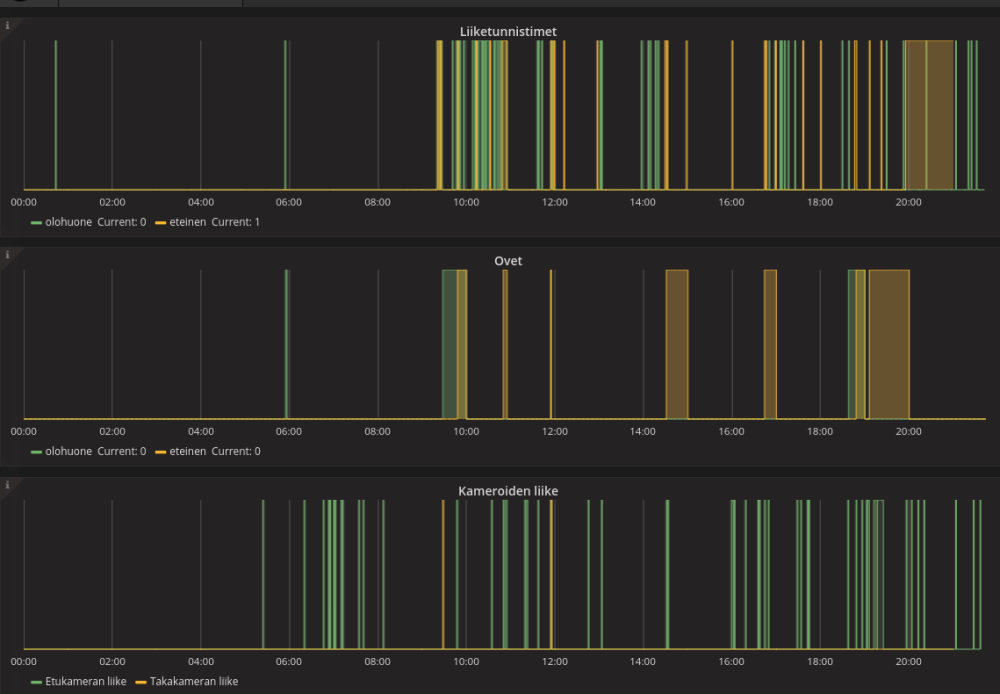
3dprint case for motion, temp and humidity sensors with radio and batteriesJust to give an update anyone building similar setup. I managed to find a day to fix the systems. I thought the step-up booster is causing noise, so I added a capasitor to step-up output. It stabilised it enough so PIR doesn't give false alarms any more. Pheeeew... Finally working properly.
-
RGB LED stripThanks a lot for sharing this! I already did the Arduino and MySensors stuff, and started thinking of writing program for it. I'm glad I found this, it fit exactly what I was doing. Here's your code a bit modified, and added some different kind of lamps for the next one looking for references: https://github.com/ikke-t/Arduino-RGB-leds-and-lightbulbs/blob/master/README.md
The additional piece here is how to command this from OpenHAB, as that's my controller. One needs to modify the RGB info via rules, it's there for reference:
https://github.com/ikke-t/Arduino-RGB-leds-and-lightbulbs/raw/master/src/rgb.rules
There are links within that file to references for how to create similar rules for RGB mangling.
-
3dprint case for motion, temp and humidity sensors with radio and batteries@Ngwpower after 10 months experience, I've modified things a bit. I never got to smaller batteries, as my access to 3D printer is quite rare. I have run into some problems with this setup.
-
PIR sensor is picky about the voltage. It starts soon creating false alarms after batteries get a bit lower on voltage. It expects good 3.3V. To fix this I added voltage boster to suck out all the power from batteries to keep it in steady 3.3V. It worked (for a while).
-
The 2.4Ghz radio is not a good idea in concrete house, along with neighbors wifis. I have lost signal from 1/3 sensors. I don't know really why, I suspect the radio signal strength and interference.
-
I think batteries won't last now for so long after putting in the voltage pump. I really don't know why, I haven't investigated, but devices disappear after some weeks. The one without voltage pump stays there for months.
-
PIR sensors again give false alerts. I don't know if it's due the heating during the winter, or dirty voltage that the voltage pump outputs.
It could be that I should just change the batteries and reboot all of them, but I haven't got around to do it now. But if you add the voltage pump, make sure to add capacitor to steady the radio power.
Temperature and door open/closed circuit works well. I wish I get the motivation to fix all the above one day soon :)
Good luck, and report back the enhancements!
-
-
How to convert received messages to integers? (MQTT)Excellent, thank you. It's too long since I've done serious coding, I didn't remember that. atoi -> atol fixed it.
-
How to convert received messages to integers? (MQTT) -
How to convert received messages to integers? (MQTT)Thanks, now it looks different, doesn't still work though. Perhaps the atoi doesn't do longs properly?
Received something of type: 32
V_IR_SEND command received...
V_IR_SEND data invalid: 16236607, ircode: 4294950975
that turns out to be:
echo "obase=16;4294950975"|bc
FFFFC03F
How does it come up with that? Need to hurry to work now, later...
-
How to convert received messages to integers? (MQTT)Hi,
I'm puzzled how message receive happens. I am building a infrared transmitter. I decoded the NEC signals from original remote, they look like this (hex): 0xF7C03F. This is power on command.
Now I want to send those signals over MQTT, which mysgw transfers over NRF24L01+ to arduino. But how to convert messages so that they look alike at both ends? is that number too big to send (3 bytes)?
As I send that exact command from arduino:
#define CMD_ON        0xF7C03F
...
send(msg_ir.set(CMD_ON));
it looks like this on MQTT looking from mosquitto_sub:
MySensorsGW/out/7/1/1/0/32 16236607When I send that back:
mosquitto_pub -h droidcam.ikenet -p 1883 -t MySensorsGW/in/7/1/1/0/32 -m 16236607the code:
uint32_t ircode;
ircode = atoi( message.data );
...
        Serial.print( "V_IR_SEND data invalid: " );
        Serial.print( message.data );
        Serial.print( ", ircode: " );
        Serial.println( ircode );
prints it out like this:
V_IR_SEND data invalid: 16236607, ircode: 4294950975the numbers don't match. 16236607 is not the original CMD_ON code.
This is the receive function:
// IR remote command codes
#define CMD_BRIGHTER  0xF700FF
#define CMD_DIMMER    0xF7807F
#define CMD_OFF       0xF740BF
#define CMD_ON        0xF7C03F
#define CMD_FLASH     0xF7D02F
#define CMD_STROBE    0xF7F00F
#define CMD_FADE      0xF7C837
#define CMD_SMOOTH    0xF7E817
#define CMD_RED       0xF720DF
#define CMD_RED1      0xF710EF
#define CMD_RED2      0xF730CF
#define CMD_RED3      0xF708F7
#define CMD_RED4      0xF728D7
#define CMD_GREEN     0xF7A05F
#define CMD_GREEN1    0xF7906F
#define CMD_GREEN2    0xF7B04F
#define CMD_GREEN3    0xF78877
#define CMD_GREEN4    0xF7A857
#define CMD_BLUE1     0xF7609F
#define CMD_BLUE      0xF750AF
#define CMD_BLUE2     0xF7708F
#define CMD_BLUE3     0xF748B7
#define CMD_BLUE4     0xF76897

void receive(const MyMessage &message)
{
  uint32_t ircode;
  Serial.print( "Received something of type: " );
  Serial.println( message.type );

	if (message.type == V_IR_SEND) {
		Serial.println( "V_IR_SEND command received..." );

		ircode = atoi( message.data );
    //ircode = message.data;
    switch (ircode) {
      case CMD_BRIGHTER:
      case CMD_DIMMER:
      case CMD_OFF:
      case CMD_ON:
      case CMD_FLASH:
      case CMD_STROBE:
      case CMD_FADE:
      case CMD_SMOOTH:
      case CMD_RED:
      case CMD_RED1:
      case CMD_RED2:
      case CMD_RED3:
      case CMD_RED4:
      case CMD_GREEN:
      case CMD_GREEN1:
      case CMD_GREEN2:
      case CMD_GREEN3:
      case CMD_GREEN4:
      case CMD_BLUE1:
      case CMD_BLUE:
      case CMD_BLUE2:
      case CMD_BLUE3:
      case CMD_BLUE4:
      {
        Serial.print( "V_IR_SEND code received: ");
        Serial.println( message.data );
        send_ircode(ircode);
        ack_ir_to_controller(ircode);
        break;
      }
      default:
      {
        Serial.print( "V_IR_SEND data invalid: " );
        Serial.print( message.data );
        Serial.print( ", ircode: " );
        Serial.println( ircode );
			  return;
		   }
    }
  }
  for (int i=0; i<5; i++) {
    digitalWrite(LED_PIN, HIGH);
    wait(100);
    digitalWrite(LED_PIN, LOW);
    wait(100);
  }
}
I suppose it has to do with data length and auto conversion of variables. It perhaps worked if I use smaller numbers to set the IR code value. But however, I'd like to understand how this is supposed to work?
BR,
-ikkePS, this is IR controlled LED light bulb from LIDL, and commands do work with the given codes.
-
3dprint case for motion, temp and humidity sensors with radio and batteriesI'm going to test how long such would work with button batteries (CR2032, 3V), and if it's long time, I could make smaller case. So far it's been on about half an year at least with two AA batteries.
One could actually stack e.g. three of those CR2032 batteries and wire them parallel in half of the size casing. Creating like "Shelves" for the batteries in the case, where they could slide in.
-
3dprint case for motion, temp and humidity sensors with radio and batteries -
3dprint case for motion, temp and humidity sensors with radio and batteriesHi home automators,
I thought I share back my case here from thingiverse for those who do want to monitor home with sensebenders and alike. I draw and 3d printed this case for my sensebender and motion + door trap sensors. One of them is running with arduino pro mini, as I didn't have sensebender for that. It's a bit tight for that, but does it's job. Feel free to modify it, and please notify me if you enhance it, so I'll get the enhancements as well :)
http://www.thingiverse.com/thing:2144946

The angle on the motion sensor allows me to point the PIR range to certain parts where I want it, by placing the case in different ways. Turn to left, right or put it above the door to aim all over.
It's not state of art, but my first 3d drawing and my first arduino job. Code is pretty much copy paste from here. The device sleeps until sleep timer hits, or motion or door trap interrupts the sleep. To get the interrupt for both, you need to leave arduino pin 2 unused from the NRF24L01+ radio, as that reserves the edge interrupt pin from sensebender. There are only 2 edge interrupt pins on those arduinos.
The code is here for the devices, like said mostly copy paste (fork): https://github.com/ikke-t/sensebender
Mysensors GW on raspi forwards the traffic as MQTT forward to my node-red. That then sends gtalk messages of events if alarm is on. I recently also added openhab to listen to MQTT bus just out of curiosity.
-
3-in-1 Humidity Temp and MotionMy sample is here, unfortunately I didn't see this thread before starting it :)
It works for temp, humidity, door and motion, and interrupts for door and motion, otherwise sleeps the intervals:https://github.com/ikke-t/sensebender
There is also pro-mini to code to monitor only door and motion.
This is also for 2.0 MySensors.
-
MQTT from RasPi MySensors GW to remote DomoticzHi,
please share your experience of setting MQTT to work with Domoticz and MS GW. Should the traffic be changed to json format or what's the deal?
I got the MySensors Raspi GW work ok, sending stuff to remote MQTT mosquitto server. The config is this:
./configure --my-gateway=mqtt --my-controller-ip-address=192,168,1,32 --my-port=1883 --my-mqtt-client-id=22 --my-mqtt-publish-topic-prefix=domoticz/in --my-mqtt-subscribe-topic-prefix=domoticz/out --my-rf24-pa-level=RF24_PA_LOWUnfortunately it won't show anything in Domoticz. I googled a bit and someone wrote Domoticz reads data in json format? Is that true? Sounds a bit weird in case of MQTT.
I'm rather close now getting things to work, please any tips welcome, too tired to google more tonight...
MQTT part is fine:
$ mosquitto_sub -t domoticz/in/# 23.0 40 -
[Solved] MQTT gateway problem -
[Solved] MQTT gateway problemafter upgrading to above mentioned 3.1.1 version from wheezy, the mysensors start to print out it sends stuff. can't see it on subs yet though.
-
[Solved] MQTT gateway problemMy mosquitto is mosquitto 3.1 - 0.15-2ubuntu1 (from ppa) and mysensors is up to date devel branch from github.
-
[Solved] MQTT gateway problemso this works:
MySensors $ mosquitto_pub -h 192.168.1.32 -t mysensors-from/0/1 -m "MySensors MQTT hello world from raspi to odroid"
mqtt-host $ mosquitto_sub -t mysensors-from/#
MySensors MQTT hello world from raspi to odroid -
[Solved] MQTT gateway problemI'm also trying mqtt. somehow I can't see the messages:
MySensors $ ./configure --my-gateway=mqtt --my-controller-ip-address=192,168,1,32 --my-port=1883 --my-mqtt-client-id=22 --my-mqtt-publish-topic-prefix=mysensors-from --my-mqtt-subscribe-topic-prefix=mysensors-to --my-rf24-pa-level=RF24_PA_LOW
MySensors $ sudo make install
...
MySensors $ sudo mysGateway -d
...
mysGateway: Attempting MQTT connection...
mysGateway: connected to 192.168.1.32
mysGateway: TSF:MSG:READ,8-8-0,s=255,c=3,t=15,pt=6,l=2,sg=0:0100
mysGateway: !TSF:MSG:SEND,0-0-8-8,s=255,c=3,t=15,pt=6,l=2,sg=0,ft=0,st=NACK:0100
mysGateway: TSF:MSG:READ,8-8-0,s=255,c=0,t=17,pt=0,l=10,sg=0:2.0.1-beta
mysGateway: TSF:MSG:READ,8-8-0,s=255,c=3,t=6,pt=1,l=1,sg=0:0
mysGateway: Attempting MQTT connection...
mysGateway: connected to 192.168.1.32
...
So GW attempts to send some stuff to mqtt server elsewhere, like that version string. But this on the server prints nothing:
$ mosquitto_sub -t mysensors-from/*I also tried with # instead of *
I've verified mqtt works, if I pub that from mqtt client, it works.
-
MY_NODE_ID AUTO doesn't work, what am I missing?@TimO ah, ok, explains as I don't have contoller configured yet. I assume it's then only such controller that speaks MySensors, not anything behind mqtt?
-
MY_NODE_ID AUTO doesn't work, what am I missing?hmmm.... this went accidentally to hardware section. I was aiming for troubleshooting. Oh well...