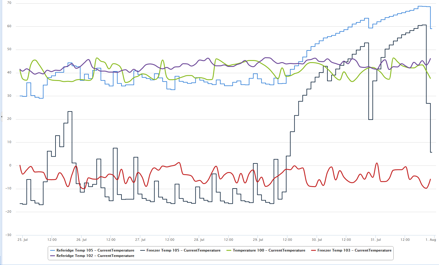
@TheoL Absolutely you can use it in a presentation. It might be useful (or not) to know that node 105 is a refrigerator/freezer combo, node 102 and 103 are in the same refrigerator/freezer, and node 100 is a chest freezer I have an external thermostat on and I use it as a refrigerator.
Posts made by Ironbar
-
RE: Refer Madness
-
Refer Madness
I have a refrigerator that has been acting funny lately. I have been watching it display non-normal temperatures for the last couple of weeks. I suspected that the thermostat in the refrigerator is going out. Thanks to mysensors, I am able to monitor the performance of several refrigerators and saw the problem early. I ordered the part I thought was at fault, moved all the vital items out of the refer, and waited (just for fun) for it to fail.
It went out Friday night. I replaced the thermostat tonight. Thanks again to Mysensors for saving 400+ dollars in meat I had in there.
-
RE: Arduino Nano and NRF24L01+PA+LNA
@Boots33 said:
NRF24L01+PA+LNA
Boots33, I completely agree. I have recently decided to rebuild my gateway and I am very pleased this thread came up so I can use the AMS1117. Any idea what the NRF24L01+PA+LNA has the potential to draw? I have looked through the data sheets but I have not came up with a definitive answer.
Although my mysensors network works very well, I am always looking for a way to improve it. I learn something new almost every day from this forum so thanks for your input.
-
RE: Gateway sketch for ENC28J60 for 2.0
Thank you. I'm not sure how I missed that.
-
RE: Arduino Nano and NRF24L01+PA+LNA
@Boots33 said:
AMS1117
I have nodes running off the LE33 and NRF24L01+PA+LNA shielded that are running on "HIGH" power. I have not had any problems with them although in theory they should not work.
I'm glad you cited the AMS1117. I will give them a try. It looks like they have a max output of 800mA. Is that correct?
-
RE: Arduino Nano and NRF24L01+PA+LNA
I'm not sure the difference in those two but check out the store page:
https://www.mysensors.org/store/#regulators
The LE33 does work with the NRF24L01+PA+LNA but I think the XC6206P332MR would be even better. The LE33 has a maximum output of 100 mA and the XC6206P332MR has a maximum output of 250mA.
-
RE: Arduino Nano and NRF24L01+PA+LNA
My experience is that it will work if you change myconfig.h to low power setting for the radio.
However, for best results I would suggest using a different power source and a LE33 or other regulator to provide significant power for the antenna. The nano only outputs 40mA.
There are a lot of threads that address this question if you dig. I am fairly new here but I use a 5 volt 2 amp power supply when I use the nano with the NRF24L01+PA+LNA. I wire the nano directly off the power supply and use a regular between the power supply and the radio.
-
Gateway sketch for ENC28J60 for 2.0
Has anyone already done a gateway sketch for the ENC28J60 for Mysensors 2.0? I did not see one in the github.
I am just trying to save a little time.
Thanks.
-
RE: Internet of Poultry - Fully automated chicken shed
First off, excellent design. Great job!
I have had one of these running for a while. I did not want mine to react to light levels because I did not want it to close during a thunderstorm, etc. and lock the chickens out. That being said, I have mine close 20 minutes after sunset and open 20 minutes after sunrise. The first couple of nights some of the chickens were locked out because they came home to late. I had to manually let them in. After a couple of days they learned quickly (despite not being very smart creatures) and they head to the house early before the door closes. After that, my camera alerts me to any movement in the house. I have only had one false alarm in a couple of months.
I have a pretty strong outdoor pen and I have still had multiple black snakes, one raccoon, and one possum get in. The raccoon ate a chicken and one snake bit one. After installing the door I have not had one injured chicken.
Mine is pretty low tech. I used a single push button and mysensored a relay board that turns a dc motor with a 3d printed gear that raises/lowers the door. I have had zero problems with it since installed. Thanks Hek!
The one big thing I learned, Transient Voltage Suppressor. I used a larger dc motor due to the weight of my door and every time the door opened it scrambled the Arduino with electric interference. Took me forever to figure out what the problem was and how to fix it.
Now if I can just figure out how to mysensor it to let me know when a chicken lays an egg.....
-
RE: my sensors and gateways will work with new versions vera firmware ?
Yes, it runs fine on the newest Vera versions. I run it on a Lite and an Edge.
-
RE: Cloud storage for home automation?
Look into the Vera. Although you do have to have Internet access to set it up, I believe the only thing stored there is your user information and a few minor things. I know you do not have to have Internet access to make it work. i. e. Power failure.
-
RE: Device Data Logging
I use an app for Vera called Datayours There is also Datamine. You can log anything you want with either app.
-
Understanding Current Requirements
Since I am new to all of this. Can someone tell me if this is even remotely correct?
From what I can find, current supply/requirements are as follows:
Arduino Nano - 500 mA total, no more than 40 ma supply to each I/O
LE33 - 100 mA supply max
SOT-23 XC6206 - 200 mA supply maxnrf24l01+ 60 mA draw max but looks like average is around 11 ma?
nrf24l01+pa+lna 115 mA draw maxIf this is correct, it would seem that using the USB powered Nano should work fine for the nrf24l01+. Does the LE33 supply enough current for the nrf24l01+pa+lna or should I use the SOT-23?
I'm sure this has been a previous thread but I am failing to find it.
Also, I noticed the Nano has a 6-12 volt recommended rating. Why? Would any performance be gained from giving it 12v?
-
RE: Which Lab Power Supply?
I am really considering this one:
EEVBlog has a little write up about it. It has a fan but it is variable and they say it is quite:
http://www.eevblog.com/forum/testgear/inside-the-new-korad-ka3305p-linear-psu/
-
RE: Repeater Node via Ethernet?
I have never tested this either but wouldn't it be better to make the second gateway and ID of 1. Both gateways could talk to the controller and remain on the same frequency. The nodes would pick whichever gateway they could talk to.
If you change frequency on the second gateway, if you had a portable device (such as a keyfob) it would only work with one of the gateways.
-
RE: NRF24L01+ range of only few meters
My guess is if the sensors work and suddenly stop, you have something else interfering with the radios. Could be a microwave, AC unit, etc.
I about gave up on this project last year. I had several units built that worked fine and then one day all of them quit. After several frustrating weeks, I discovered my wifi router somehow was interfering with the units. It was an old unit and I needed to replace it. After it was gone, everything went back to working correctly.
-
RE: My Gateway Project Box
It is the shielded nrf24l01+lna/pa. I do not have any scientific test for how well they work.
My real world test is that I was having trouble transmitting directly from my gateway to two out buildings near my house (~150m). In theory, the non-shielded should have worked but it is through several brick walls and they would only communicate about every fifth transmit. After switching the gateway and outbuildings to shielded radios, they receive every transmission.
I had to change the transmit power to low because they do indeed interfere with themselves.
Per our previous discussion, I believe you are correct and they are not completely shielded correctly. At some point this year, I want to be able to transmit from my home to my well house (~150m - brick structure) and then to my front gate (~800m). It is not LOS because of hills and trees.
Part of the design of this enclosure was the idea that you could wrap the interior of it with aluminum foil to shield the radio. Then you mentioned the shielded radios so I thought I would give them a try. Overall, I think the results between the two would be similar.
To most it would seem unimportant for radios to communicate directly with the gateway due to the mash network. The problem I have is, there are mission critical items in my network I want to work. For example, if power goes out: My gateway is running on battery backup as well as my router, modem, etc. If I have a battery operated sensor monitoring the temperature of my baby chicks, it will continue to monitor them. If I rely on a mesh network, and one of the relay sensors goes out, I could loose the sensor monitoring the chicks.
-
RE: My Gateway Project Box
Thank you.
Here is the enclosure on thingiverse:
http://www.thingiverse.com/thing:1410018
I have another version for non-shielded radios as well. I have not uploaded it to thingiverse yet though.
The logo is for open-source hardware. I didn't want to violate any copyrights by putting on the MySensors logo and uploading to thingiverse. Plus, the MySensors logo is hard to 3d print.
-
RE: Sensebender Micro Case
Sure. Here it is on thingiverse:
http://www.thingiverse.com/thing:1410004
The battery holder is a single holder with two AA batteries. The batteries are ran in series. To be honest, I can't remember where I bought the holders but I like them because they clip on like a 9 volt so you can easily disconnect the battery holder from your project.
-
My Gateway Project Box
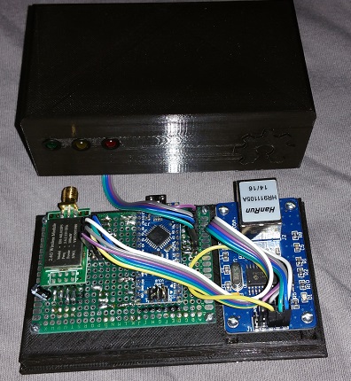
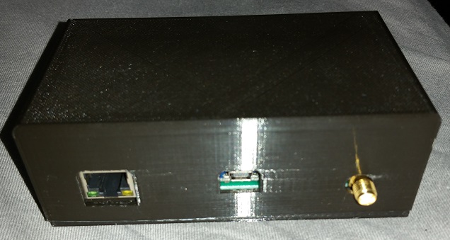
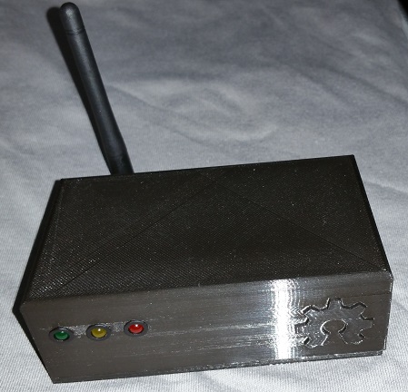
Here is my gateway enclosure. I know the solders are terrible but it works awesome.
-
Sensebender Micro Case
Here is my take on a case for the Sensebender Micro. I left space at the top so it could be adapted for a proxy sensor, etc. These are for my refrigerator and freezer so they don't need to hang.
They still need a little sanding...
Here is my attic sensor w/ a hanging tab:
-
RE: MySensors Micro - Other Suppliers
Sounds like your problem is a little different than mine but Itead offered to send me an invoice and pay directly with Paypal without using their site. I'm sure they will do the same for you. To my knowledge, there are no other suppliers.
-
RE: [SOLVED] ESP8266 fails to boot with NRF24L01+ connected
I also had one that would not change from 5v to 3.3v. I don't remember which brand it was but it had a switch instead of a jumper. It took me a long time to figure out that it was the problem.
-
Vera Controller Organization
Currently I have my home automation setup as a normal person would:
Main House
Bedrooms
Kitchen
Office
Den
etc.
Garage
Outside Lights
etc.I am about to merge my "sandbox" with all of MySensors with my main house as well as my Detatched Garage, Chicken House, Shop and Barn. I would like to hear any suggestions on how to organize them all to make sense in Vera.
I was thinking like this:
A-House
Master Bedroom
Guest Bedroom
Bathroom
etc.
B-Aparment
Bedroom
Office
Living Room
C-Barn
Stalls
Tack Room
etc
D-Shop
Outside Lights
Lights
etcHow do you organize your home automation controller? I would like to hear any/all suggestions.
Thanks.
-
GE Smart Fan Control
The new Smart Fan Control by GE is nice for ZWave. You can set your fan at any percentage fan speed.
I love it.
Nothing to do with MySensors but a very nice addition.
-
RE: Vera UI7 What if a sensor is not reporting?
I did manage to figure out a work around for this problem:
I created a virtual switch called Dead Node Alert. This gives me a visual switch that shows if all nodes are responding or if one has failed to report.
I then use PLEG and set two conditions: 1) compares last update vs. current time. If more than x seconds since ANY nodes have reported they flip the switch to off. 2) compares last update vs current time. If less than x seconds since ALL nodes have reported then its flips the switch on.
So now I don't have to worry about stuff in my freezer spoiling if my temperature sensor does not respond and my freezer quits. Sure beats looking at all the last updates to make sure they are responding.
If anyone needs example PLEG conditions or inputs let me know. It would be great if this were native to the plugin somehow!
-
RE: Long Range Transmission
@Oitzu said:
@Ironbar said:
I have not had much luck with the nrf24l01+ pa/lna modules. They only seem to transmit about 300m. I'm going to setup an outdoor test this summer to see if I can get them to transmit further.
Are you getting 1000m out of them?
I've never tried the shielded modules. I didn't even know they existed. I guess I will throw them in the test as well. I will still be highly surprised if I can get 800 meters out either one of them.
Thanks for the info!
I got 1000m on clear line of sight out of them, yes. Its a matter of shielding, clean power supply and correct antenna alignment.
Are you shielding the antennas on both ends to get the 1000m? I'm rebuilding my gateway now so I wonder if it would be worth waiting on a shielded antenna. The shielded antennas I bought say 1300m line of sight.
@Lawrence-Helm said:
I have wondered about putting a solar powered repeater in the middle...
Is doable, but you will probably need to use a rather big solar cell and battery. I'm currently building some nrf24l01+ nodes with 20 watt solar cells. I think i can give some results in about 1 month.
I would be very interested to see this project. My barn is about half way down my driveway at 400m so I may be able to put a repeating node in there. My problem is, I do not have clear line of sight to my mailbox because my property is hilly. I would have to put a antenna on my barn that sticks up in the air 15m and I do not want to do that.
-
RE: Long Range Transmission
I have not had much luck with the nrf24l01+ pa/lna modules. They only seem to transmit about 300m. I'm going to setup an outdoor test this summer to see if I can get them to transmit further.
Are you getting 1000m out of them?
I've never tried the shielded modules. I didn't even know they existed. I guess I will throw them in the test as well. I will still be highly surprised if I can get 800 meters out either one of them.
Thanks for the info!
-
Long Range Transmission
Has anyone tried to use any variants of the radios to cover a very long range ~800 meters? I ran across this:
I wonder if this could be used as a bridge between sensors to cover a longer range. Or am I reinventing the wheel here?
I have a gate that is 800m away that I would like to open/close via mysensors.
-
RE: 💬 Sensebender Micro
Crazy but there was a space after my city name that was preventing it from working. I would have never thought it was that picky. Ordered 5 and I cannot wait to see how well they work!
-
RE: 💬 Sensebender Micro
Let me know if you manage to order them. The IMALL website won't let me actually place an order due to it sending the wrong address to Paypal. I'm curious if it is just me...
-
Mystery Node ID
Can someone please explain this? I only have two nodes, 105 and 106 which are both hard coded into the sketches. I have this mystery node 32 that shows up on the gateway and I cannot figure out what it is.
from gateway:
0;0;3;0;9;read: 32-32-0 s=0,c=1,t=0,pt=7,l=0,sg=0:70
0;0;3;0;9;ver mismatch
0;0;3;0;9;read: 106-106-0 s=255,c=0,t=17,pt=0,l=5,sg=0:1.5.1
106;255;0;0;17;1.5.1
0;0;3;0;9;read: 106-106-0 s=255,c=3,t=6,pt=1,l=1,sg=0:0
106;255;3;0;6;0
Finished
106;255;3;0;6;I
0;0;3;0;9;send: 0-0-106-106 s=255,c=3,t=6,pt=0,l=1,sg=0,st=ok:I
0;0;3;0;9;read: 32-32-0 s=255,c=1,t=1,pt=0,l=16,sg=0:
0;0;3;0;9;ver mismatch
0;0;3;0;9;read: 32-32-0 s=255,c=1,t=1,pt=0,l=16,sg=0:
0;0;3;0;9;ver mismatch
0;0;3;0;9;read: 106-106-0 s=255,c=3,t=12,pt=0,l=3,sg=0:1.1
106;255;3;0;12;1.1
0;0;3;0;9;read: 106-106-0 s=0,c=0,t=6,pt=0,l=0,sg=0:
106;0;0;0;6;
0;0;3;0;9;read: 32-40-0 s=0,c=0,t=0,pt=7,l=0,sg=0: 0
0;0;3;0;9;ver mismatchfrom node:
send: 106-106-0-0 s=255,c=0,t=17,pt=0,l=5,sg=0,st=ok:1.5.1
send: 106-106-0-0 s=255,c=3,t=6,pt=1,l=1,sg=0,st=ok:0
read: 0-0-106 s=255,c=3,t=6,pt=0,l=1,sg=0:I
sensor started, id=106, parent=0, distance=1
send: 106-106-0-0 s=255,c=3,t=11,pt=0,l=18,sg=0,st=ok:Temperature Sensor
send: 106-106-0-0 s=255,c=3,t=12,pt=0,l=3,sg=0,st=ok:1.1
send: 106-106-0-0 s=0,c=0,t=6,pt=0,l=0,sg=0,st=ok:
send: 106-106-0-0 s=0,c=1,t=0,pt=7,l=5,sg=0,st=ok:70.5and node 105 looks the same.
Am I just reading this wrong or is something else going on?
Thanks for any help.
-
PCB Identity Please
Can someone please help me to identify this board? I'm pretty sure I bought if off a link from this forum. Been to long...
I am trying to find the specs/etc. Can't let a board go to waste!
Thank you.!
-
RE: ESP8266 Gateway can't Press start for inclusion
Try changing browsers. I've had that happen in other browsers but it seems to work fine with Chrome.
-
Node send fail - No return ack?
I built several temp sensors and a ENC28J60 nano gateway last year and they all worked pretty good. I had to put the project down for the summer and I picked it back up last week.
I noticed that MySensors had changed to 1.5 so I set everything back up and reflashed my gateway and a temp sensor to new version. I also completely restarted my Vera so I could completely start over.
Nodes send to gateway, gateway sends to Vera. Seems to all work except my nodes (I've tried several on static node ids and auto) all seems to st=fail. Every blue moon it will give a st=ok. The gateway is receiving the data and posting it to Vera but it does not seem to be sending back an ack to the node. Any idea what is going on here?
From node:
send: 105-105-0-0 s=255,c=0,t=17,pt=0,l=5,sg=0,st=fail:1.5.1 send: 105-105-0-0 s=255,c=3,t=6,pt=1,l=1,sg=0,st=fail:0 sensor started, id=105, parent=0, distance=1 send: 105-105-0-0 s=255,c=3,t=11,pt=0,l=18,sg=0,st=fail:Temperature Sensor send: 105-105-0-0 s=255,c=3,t=12,pt=0,l=3,sg=0,st=fail:1.1 send: 105-105-0-0 s=0,c=0,t=6,pt=0,l=0,sg=0,st=fail: send: 105-105-0-0 s=1,c=0,t=6,pt=0,l=0,sg=0,st=fail: find parent send: 105-105-255-255 s=255,c=3,t=7,pt=0,l=0,sg=0,st=bc: send: 105-105-0-0 s=0,c=1,t=0,pt=7,l=5,sg=0,st=fail:22.5 send: 105-105-0-0 s=1,c=1,t=0,pt=7,l=5,sg=0,st=fail:21.7 send: 105-105-0-0 s=1,c=1,t=0,pt=7,l=5,sg=0,st=fail:21.6
From gateway:
0;0;3;0;9;gateway started, id=0, parent=0, distance=0 0;0;3;0;9;read: 105-105-0 s=1,c=1,t=0,pt=7,l=5,sg=0:22.1 105;1;1;0;0;22.1 0;0;3;0;9;read: 105-105-0 s=1,c=1,t=0,pt=7,l=5,sg=0:22.0 105;1;1;0;0;22.0 0;0;3;0;9;read: 105-105-0 s=1,c=1,t=0,pt=7,l=5,sg=0:22.1 105;1;1;0;0;22.1 0;0;3;0;9;read: 105-105-0 s=1,c=1,t=0,pt=7,l=5,sg=0:22.0 105;1;1;0;0;22.0
These were not taken at the exact same time but it should give an idea of what is going on. I'm sure it is something simple I am missing from being out of the loop so long.
I thought I had a problem with the gateway so I changed out the nano and the antenna. Nothing changed.
Thank you for any help.
-
Vera UI7 What if a sensor is not reporting?
I finally have a couple of temperature sensors working correctly in my setup but I have a question. I've noticed that if the sensor stops reporting (unplugged, out of range, etc) that Vera simply reports its last state. So if I unplug one of my temperature sensors it always shows the last temperature it was at.
How are people dealing with this issue? Is there something I can add to the sketch to make it show in error or are people writing a scene that says "if sensor doesn't change in x hours send alert."
Thanks.
-
RE: What am I missing?
Thanks jeylites.
I stated with a Nano and a W5100 module but I think the W5100 module was bad because I never could even get it to run a web server sketch. I didn't fully understand the wiring back then so I gave up and bought the Uno and shield because I figured it can't be wired wrong.
I get 3.270 volts to the radio. I ordered some 9v adapters that I will try when they get here. In the mean time I guess I will order another W5100 and see if I can get the nano to work.
Anyone have any other ideas? It seems like there would be a way to see if the radios are actually even broadcasting anything.
-
What am I missing?
I'm new here and having trouble.
I built a gateway using UNO R3 Clone and genuine UNO Shield. Wired according to mysensors website. Removed SPI comment. Uploaded and added it to Vera UI7. This is what the serial monitor reads:
0;0;3;0;14;Gateway startup complete.
When I start the inclusion process:
0;0;3;0;2;Get Version
0;0;3;0;2;1.4.1
0;0;3;0;5;1I built a temperature sensor using a dallas temperature sensor based on a nano and wired it according to mysensors website and commented the SPI again. It works and reports the temperature corrects but reports:
send: 10-10-255-255 s=255,c=3,t=7,pt=0,l=0,st=fail:
sensor started, id 10
send: 10-10-255-0 s=255,c=0,t=17,pt=0,l=5,st=fail:1.4.1
send: 10-10-255-0 s=255,c=3,t=6,pt=1,l=1,st=fail:255
send: 10-10-255-0 s=255,c=3,t=11,pt=0,l=18,st=fail:Temperature Sensor
send: 10-10-255-0 s=255,c=3,t=12,pt=0,l=3,st=fail:1.0
send: 10-10-255-0 s=0,c=0,t=6,pt=0,l=5,st=fail:1.4.1
send: 10-10-255-0 s=0,c=1,t=0,pt=7,l=5,st=fail:26.6I tried to give it a static node number of 10 but still have the st=fails.
What am I doing wrong? Apparently the units are not talking to each other. I have worked through the mysensors trouble shooting. There are 4.7 uf capacitors on both radios. All parts are ordered from the links on mysensors.
I would appreciate any help anyone can give. Thanks.