Hi
Yes, it works for me.
You can read more about the json part here:
https://www.domoticz.com/wiki/Domoticz_API/JSON_URL's#Lights_and_switches
Br
Lemme
Hi
Yes, it works for me.
You can read more about the json part here:
https://www.domoticz.com/wiki/Domoticz_API/JSON_URL's#Lights_and_switches
Br
Lemme
@masmat
Just an idea...
As I recall, Domoticz only responds to changes. So if you send '1' to a switch that are already have '1' status, nothing happens. So I suggest that you first send '1' when the button is pressed. Then after for example 500ms you send '0'. That way the button switch will toggle.
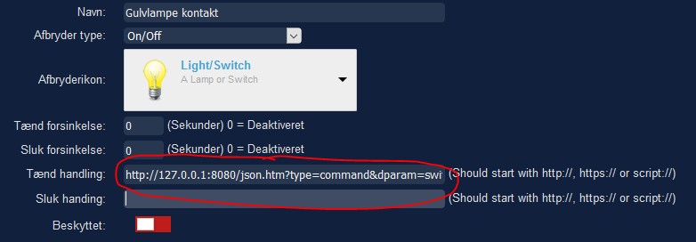
Now - in the switch settings, you can send a ‘Toggle’ command to the node that controls the relay:
http://127.0.0.1:8080/json.htm?type=command&dparam=switchlight&idx=42&switchcmd=Toggle
In your case the ‘idx=42’ should correspond to your relay node.
With this setup, you should be able to toggle your relay with single presses on your button.
Hi
I upgraded as well, and did not have any problems. So this is a wild guess....:
It seems that you use a using a different skin than standard. I remember that I have read somewhere that sometimes different skins can cause strange problems.
What if you revert back to the original skin and reboot - what happens then?
/F
In this use case, I need to control my Philips Hue light. The issue with Philips Hue lights bulbs are that they need to be connected to mains always for controlling them. If the light bulbs are turned off by the wall switch, you cannot turn them on again remotely. You have to go to activate the wall switch again. I don’t want to accidentally turn off the power to the light bulbs, so I cannot control them. And I do not want to use the separate switches sold by Philips. I want to use my existing wall switches only.
So, I have solved this issue in a combination with MySensors, Domoticz and the Philips Hue gateway. In this description I have only described the wall switch part.
The obvious choice is to build a self-contained MySensor switch into the wall. Complete with a DC power converter and a relay. The issue here is the Danish wall switches produced by LK. They are more or less a standard in DK. They have a very nice look, but the casing behind the switch are small, and leave not much room for electronics.
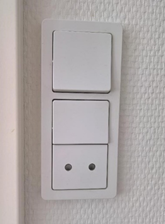
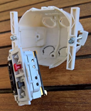
It would be impossible for me to create such a small self-contained relay unit, using standard components. Another issue is regulation and insurance. I am not quite sure if I would be covered, if the electronics – against all odds, should caught fire within the wall.
So I decided to create a battery driven MySensor switch, that would fit nicely inside the LK housing, using the existing LK switch.
I had these requirements for the switch:
• Should fit inside the LK casing, using the existing LK switch
• Long range
• Low power consumption
• Robust and self-healing
• Easy to perform reset and re-programming
• Follow regulations
Small housing
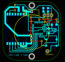
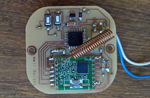
I made the PCB as small as I could, fitting it into the LK housing. As I develop and etch the PCB myself, I have to use single side print. All components are SMD to achieve the smallest possible footprint.
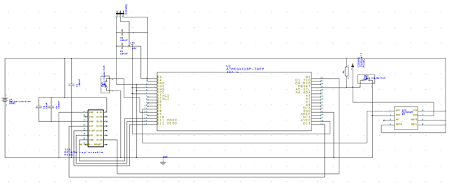
Long range
I have made several experiments with NRF24L01+ in the house. In my case they were not a good choice. The range are simply not good enough, and installing them inside walls make it worse. I need these things to work – every single time.
The choice was RFM69 using 433MHz. This frequency has an extreme good coverage, and I have not seen any lost packages using that radio.
Low power
To achieve low power for extending battery life, two main things can be addressed. Reduce the clock frequency of the Atmega328 and bring it to Sleep mode when not used.
In my experiments I first used 1MHz as the clock frequency. But when I did some analysis of the data packages sent, I could see that there were data loss. It worked, but it was not reliable or stable. I then tried the 8MHz clock frequency. And here all data packages came through. So I ended up with an 8MHz bootloader.
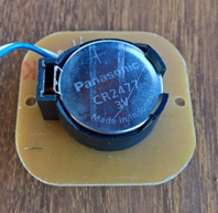
Also, I used a coin cell for a small foot print and for easy changing of battery. To achieve long life, I used the CR2477 type. It has the capacity of 1000mAh.
Self-healing
As the switch would be installed behind the wall switch, it would also mean that easy access to it would not be possible. So it has to be a robust design that requires no maintenance. Sometimes electronics can fail without any obvious cause. So I decided to implement a Watch Dog to reset the processor if it should fail. That should catch most problems. I use the MAX6369 for that.
Re-programming
New versions of MySensors emerge now and then. Maybe I need to upgrade to a version later in time. And maybe I need to reprogram the switch for other functions – who knows. It could also be that I need to clear the memory of the switch for some reason. So an easy way of doing this would be required.
When I program the switch, I use a USBasp programmer. I solder the wires to the same pads as where the RFM69 are placed. But as the RFM69 should not be applied with more than 3.3V, and the Atmega328 are programmed with a higher voltage, I need to remove the radio before programming. When the RFM69 first are soldered to the PCB, it is almost impossible to unmount. So I have made the PCB pads to just align with the radio, but not letting the copper parts touch each other. That way the radio can easily be de-soldered and the Atmega re-programmed.
I have applied two switches for Reset and Memory purposes. The Reset switch just resets the Atmega. But when the Memory switch are pressed at the same time as the Reset switch (or the battery inserted), a small code that clear the memory are executed.
Regulations
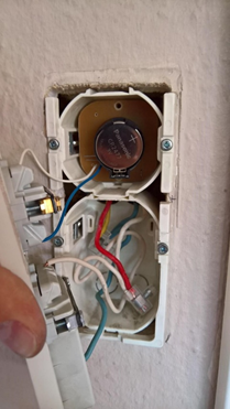
I need to have the power outlet on the ceiling to always carry 240V. This is for the Philips Hue light bulbs to be connected all the time. In order to do that, I assemble and connect the 240V wires in the LK housing, so that the power is always on. Doing this inside the LK housing is the right way as to avoid breaking any rules or regulations regarding high voltage installation. And it is completely safe.
As there is no way to do this assembly within the LK housing where the wall switch is, I drove the wires down into the second housing and assembled them there.
Conclusion
Everything works like a charm. All requirements are fulfilled, and the solution even have been accepted by the wife. The reason I know this, is that there have been no complaints or sarcastic comments. It is a complete wife transparent solution. It just works.
The Code
// 8MHz Bootloader
// Enable debug prints to serial monitor
//#define MY_DEBUG
//#define MY_BAUD_RATE 19200

//#define MY_RADIO_NRF24
#define MY_RADIO_RFM69
#define MY_RFM69_FREQUENCY RFM69_433MHZ
#define CHILD_ID_0 0
#define CHILD_ID_1 1
#define CLEAR_EEPROM_PIN 8  // Arduino Digital I/O pin for clear EEPROM

#include <MySensors.h>
#include <EEPROM.h>

volatile int batteryTimer = 1440;
volatile boolean ack = false;

MyMessage msg1(CHILD_ID_0, V_LOCK_STATUS);
MyMessage msg2(CHILD_ID_1, V_VOLTAGE);

void before()
{
  ///////////////////////////////// Clear EEPROM as the first thing, if butten is pressed /////////////////////////////////////////////////////
  pinMode(CLEAR_EEPROM_PIN, INPUT_PULLUP); // Setup the clear EEPROM button and activate internal pull-up
  int value = digitalRead(CLEAR_EEPROM_PIN);  // read input value
  if (value == LOW) {         // check if the input is LOW (button closed)
    for (int i = 0; i < 512; i++) {
      EEPROM.write(i, 0xff);
    }
  }
  ////////////////////////////////////////////////////////////////////////////////////////////////////////////////////////////////////////////
}

void presentation()
{
    sendSketchInfo("Wall switch - single", "2.2.0");
    wait(100);
    present(CHILD_ID_0, S_LOCK);
    wait(100);
    present(CHILD_ID_1, S_MULTIMETER);
    wait(100);
}

void setup()
{
  pinMode(7, OUTPUT);  // WatchDog pin. Initialize digital pin 7 as an output.
  digitalWrite(7, LOW); // Set pin to Low
  pinMode(3, INPUT_PULLUP);// Interrupt pin. Configure wake up pin 3 as Interrupt input with pullup.

  transmitValue(digitalRead(3));
  wait(100);
  batterystatus();
  wait(100);
}


void loop()
{
  int trigger = sleep(1, CHANGE, 50000); // Use Interrupt 1, wake up on 'Change' signal, sleep for 50 seconds or until interrupt. Returns interrupt number.

  if (trigger == 1) {  //Interrupt triggred by sensor;
      transmitValue(digitalRead(3));
      watchDog();
  } else { //Triggered by 50 seconds timer interrupt
    watchDog();
    batterystatus();
  }
}

////////////////////////////////////////////////// WatchDog trigger - keep alive signal ////////////////////////////////////
void watchDog()
{
  digitalWrite(7, HIGH);
  wait(1);
  digitalWrite(7, LOW);
}

////////////////////////////////////////////////// Send battery status every 24 hours ////////////////////////////////////
void batterystatus()
{
  if (batteryTimer == 1440) {
    float batteryPcnt = readVcc();
    send(msg2.set(batteryPcnt, 3));
    batteryTimer = 0;
  }
  ++batteryTimer;
}

////////////////////////////////////////////////// Transmit session ///////////////////////////////////////////////////
void transmitValue(int value)
{
  ack = false;
  int retries = 0;
  while (ack == false) { // Keep sending until 'ack' are recieved from GW
    send(msg1.set(value), true);
    wait(150);
    if (retries == 5) { // But stop after 5 retries. This saves battery.
      ack = true;
    }
    ++retries;
  }
}

void receive(const MyMessage &message) {
  if (message.isAck()) {
    ack = true;
  }
}


float readVcc() {
  // Read 1.1V reference against AVcc
  // set the reference to Vcc and the measurement to the internal 1.1V reference
#if defined(__AVR_ATmega32U4__) || defined(__AVR_ATmega1280__) || defined(__AVR_ATmega2560__)
  ADMUX = _BV(REFS0) | _BV(MUX4) | _BV(MUX3) | _BV(MUX2) | _BV(MUX1);
#elif defined (__AVR_ATtiny24__) || defined(__AVR_ATtiny44__) || defined(__AVR_ATtiny84__)
  ADMUX = _BV(MUX5) | _BV(MUX0);
#elif defined (__AVR_ATtiny25__) || defined(__AVR_ATtiny45__) || defined(__AVR_ATtiny85__)
  ADMUX = _BV(MUX3) | _BV(MUX2);
#else
  ADMUX = _BV(REFS0) | _BV(MUX3) | _BV(MUX2) | _BV(MUX1);
#endif

  delay(2); // Wait for Vref to settle
  ADCSRA |= _BV(ADSC); // Start conversion
  while (bit_is_set(ADCSRA, ADSC)); // measuring

  uint8_t low  = ADCL; // must read ADCL first - it then locks ADCH
  uint8_t high = ADCH; // unlocks both

  long result = (high << 8) | low;
  result = 1125300L / result; // Calculate Vcc (in mV); 1125300 = 1.1*1023*1000
  float battery = result / 1000.0;
return battery; // Vcc in volts```Try this:
gw.sleep(1, CHANGE, 0);
I cannot see that your code are handling ACK's. So if Domoticz are expecting ACK, and your code do not respond, it could cause the problem.
I have had an issu myself with the error "Error sending switch command, check device/hardware !". I first disabled the ACK - update, and then enabled ACK - update, and then it worked correctely.
You find it at the buttom of the screen.
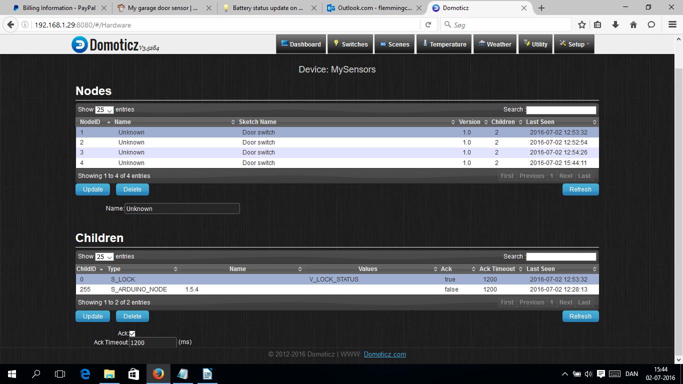
Hi dbemowsk
Regarding your first question - could it be that Domoticz are expecting an ACK from the node? ACK are enabled by default on all childs created. You could try to disable it.
Br
Lemme
Yes - you are right.
I have now done a whole series of tests, where I created nodes in different configurations, and read the debug information.
It is not the present() is I was thinking, that creates the node in the controller. At the Domoticz forum, gizmocuz said that it does not matter what comes first - present() or sendSketchInfo().
So the issue about creating nodes in a consistent way are not related to this. So far so good...
Last evening I tried the stable version 1.5.4. I created ten 100% identical nodes i an row, without any errors. It could be that there are still some issues with the v2 development version, or that the new version are handled differently, and that is not implemented in Domoticz yet.
It seems that I have to go with 1.5.4 for now, and wait until v.2 are released and these issues are sorted out between MySensors and Domoticz.
Thanks for the feedback!
Br
Lemme
Hi Nca78
I do not have the opportunity to see the debug information, as my node are on a custom PCB. But I think that you are onto something here. All the examples in the v2 development version, are presenting like this:
void presentation() {
  sendSketchInfo("Door switch", "1.0");
  present(CHILD_ID, S_LOCK);
}
But is this the correct sequence? I would assume that present() should be initiated first, to let the controller create the node. Only then should sendSketchInfo() be sent, to fill in the 'nice to have' information. In the MySensor documentation it is stated that sendSketchInfo() is optional, so it is not needed for the controller to create the node. So I can simply not understand why the examples start with sendSketchInfo() to create the node. It should/could make some strange results in the controller.
I would assume that this is the right sequence. The node are first presented for the controller and created. The node are the updated with the sketch info.
void presentation() {
  present(CHILD_ID, S_LOCK);
  sendSketchInfo("Door switch", "1.0");
}
Again, maybe this is for a developer to answer. Does it matter what comes first during the ‘presentation’ - what is the correct sequence?
Br
Lemme
I posted this on the Domoticz site as well...
It seems that things are partly begin to work correctly. I found out that all examples had 'sendSketchInfo' first. I also found delays in one of the examples, and I implemented that as well. This is how it looks like now:
void presentation() {
  sendSketchInfo("Door switch", "1.0");
  wait(500);
  present(CHILD_ID, S_LOCK);
  wait(500);
}
I also updated MySensors library, there were som TransportProcess cleanup yesterday, and it seems that some of those changes included some changes to the presentation as well.
All nodes are now created with only 1 child of 0. So I must conclude that creating child_id of 255 is wrong.
As this seems to work now, there are now another problem. Only one of the nodes are identified correctly as an S_LOCK node. The variable V_LOCK_STATUS are identified correctly on all nodes.
All nodes now have 1 child:

This node have both S_LOCK node the variable V_LOCK_STATUS identified correctly

The remaining nodes are missing the S_LOCK, but the variable V_LOCK_STATUS identified correctly

Any clue why this is happening?
Br
Lemme
Still - I think this question is relevant in this forum, and maybe for a developer to answer:
Does it matter what comes first during the ‘presentation’ (present/sendSketchInfo or the other way around)? What is the correct sequence?
This is how I do the presentation:
void presentation() {
  present(CHILD_ID, S_LOCK);
  sendSketchInfo("Door switch", "1.0");
}
Br
Lemme
@AWI
Thanks - I will try the Domoticz forum to see if I can get closer to an answer.
Br
Lemme
As I wrote, I use the latest v.2 beta version of MySensors, and latest development version of Domoticz. Both HW and SW are 100% identical on the 3 nodes. This issue was seen with other versions of Domoticz also.
I should add that I use a serial gateway based on the RFM69 radio.
Hi all
First, I use the latest v.2 beta version of MySensors, and latest development version of Domoticz.
When I add my 3 identical Door Switches, they are created with either 1 or 2 children. All children are created with a child ID of 0 (S_LOCK ). But some of them are also created with a child ID of 255 (S_ARDUINO_NODE ).
What is the normal behaviour – 1 or 2 children created?
Should I just ignore it and delete the 255, S_ARDUINO_NODE – would there be any implications in doing this?
Should I contact the Domoticz forum, as this is a flaw?
This is my 3 Nodes:

Here the node are created with only 1 Child:

Here are a similar node created with 2 Children:

I have been looking in MyConfig.h for the different levels to set for RF24_PA_LEVEL and RF24_PA_LEVEL_GW, but could not find it in the documentation. Only RF24_PA_MAX and RF24_PA_LOW was shown as options.
In the forum I found that all these options can be used - RF24_PA_MIN, RF24_PA_LOW, RF24_PA_HIGH or RF24_PA_MAX.
I suggest that these options are added as remarks in MyConfig.h.
OK - I deleted 'MySensors' folder in the library, and downloaded the ZIP once again, and copied the new 'MySensors' into it.
Now it works!
I am using the NFR24 radio. So I did not change anything in the sketch. But I still get the error.
The only thing I did was to copy the whole ZIP file from Github to the Arduino library, and compiling the sketch. Should it be done in another way?
But just to be clear, the sketch that I am supposed to be using for the gateway are now called 'GatewaySerial.ino' and do not contain a 'GatewayUtil.h' - right?
Hi
I was about to test the hartbeat function in development branch v.2. To start with I wanted to update the gateway (Serial gateway - Arduino Nano).
I could not find 'SerialGateway.ino' so I was assuming that I was to use the sketch 'GatewaySerial.ino'.
But it does not compile, and come with this error:
#error No forward link or gateway feature activated. This means nowhere to send messages! Pretty pointless.
The code seems also different, and in the old sketch there was also this file - GatewayUtil.h.
How do I update the gateway to the new development v2?
Hi again
Thanks - I tried to clean up using a YAML translator, and using Notepad2.
I forgot to set the baudrate to 115200 in Windows, changed that, but still no luck.
I give up, and continue with Domoticz.
Thanks for helping.
OK - I will check the formatting.
But the example file are Linux based, I use Windows, and my serial port are Com 5.
I would be nice if someone with a Windows configuration would share their working config. One thing is the formatting, but I am not sure that I have written the correct com5 statement.
Br
Flemming