I have started to use ESP8266 for some of my devices with my Vera. So a combination of mysensors and esp's.
How would I go around reading values via WIFI only(esp8266) ? I can do a HTTP request to put values but how would I do a READ ?
/M
I have started to use ESP8266 for some of my devices with my Vera. So a combination of mysensors and esp's.
How would I go around reading values via WIFI only(esp8266) ? I can do a HTTP request to put values but how would I do a READ ?
/M
@ferpando You can enable a watchdog timer on your Arduino. If your code hangs your Arduino, it should reset/reboot it. But not sure that would reset the radio.
Found good description -> http://www.megunolink.com/how-to-detect-lockups-using-the-arduino-watchdog/
@Andreas-Maurer Nice looking board!!
How often do you read from the DHT11, might not be an issue. But think you need to wait 1-2 sec pr. poll. (Depending on DHT11/22)
Just add blink code or add an ekstra led to see if the code is running..
And you have added a cap for the radio ?
Try to add a blink, just to see if the board crashed/freezes. If not it's properly the radio.
What are you powering it with ?? 5v usb or battery ??
I was looking for the same thing. I need to implement a status on the node depending on the status of a device on my Vera. But from what I can read we "only" can read last reported value from the controller. That does not guarantee that it's valid compared too current status in the Vera.
Guess you might need to create a script on the vera that updates the status to the controller ?
Ran the nRF24 GettingStarted and got this from two different nRF24's
Standard nRF24L01+
STATUS = 0x0e RX_DR=0 TX_DS=0 MAX_RT=0 RX_P_NO=7 TX_FULL=0
RX_ADDR_P0-1 = 0xa8a8e1fc62 0xf0f0f0f0d2
RX_ADDR_P2-5 = 0xff 0xc4 0xc5 0xc6
TX_ADDR = 0xa8a8e1fc00
RX_PW_P0-6 = 0x20 0x20 0x20 0x00 0x00 0x00
EN_AA = 0x3b
EN_RXADDR = 0x07
RF_CH = 0x4c
RF_SETUP = 0x07
CONFIG = 0x0f
DYNPD/FEATURE = 0x00 0x06
Data Rate = 1MBPS
Model = nRF24L01+
CRC Length = 16 bits
PA Power = PA_HIGH
nRF24L01+ with Antenna
STATUS = 0x0e RX_DR=0 TX_DS=0 MAX_RT=0 RX_P_NO=7 TX_FULL=0
RX_ADDR_P0-1 = 0xe7e7e7e7e7 0xf0f0f0f0d2
RX_ADDR_P2-5 = 0xc3 0xc4 0xc5 0xc6
TX_ADDR = 0xe7e7e7e7e7
RX_PW_P0-6 = 0x00 0x20 0x00 0x00 0x00 0x00
EN_AA = 0x3f
EN_RXADDR = 0x03
RF_CH = 0x4c
RF_SETUP = 0x07
CONFIG = 0x0f
DYNPD/FEATURE = 0x00 0x00
Data Rate = 1MBPS
Model = nRF24L01+
CRC Length = 16 bits
PA Power = PA_HIGH
The one with antenna's adresse looks kind of "strange", but don't know if we can read anything out of this ????
So can we identify the "fakes" vs "real fakes" by dumping chip info or is that 100% faked to?
Yes, Nano is a bit bigger, but have own usb-serial chip so you can program it directly and have onboard 5-3.3 output. Keep forgetting that:) So if size is not an issue, got with the Nano...
Check the connecting radio and Connecting Ethernet Gateway. And get some 5.0->3.3v voltage regulators. Dirt cheap on ebay.
For ease of use I would go with the Uno + W5100 shield. Not that much more expensive vs using a Pro Mini, you will have less wiring. And then use Pro Mini's for sensors..
Check this, very good take Dave have on it.. FTDI Gate
I got hit hard at the time, had 5 chips that stopped working, was going MAD until I figure it out.
Was looking into the same and ordered 2 different 230/110v to 5v of ebay to get a cheap 5v powersource. Just got them today.
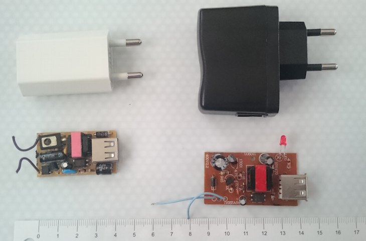
The White around $1.5 and the Black was $1.0
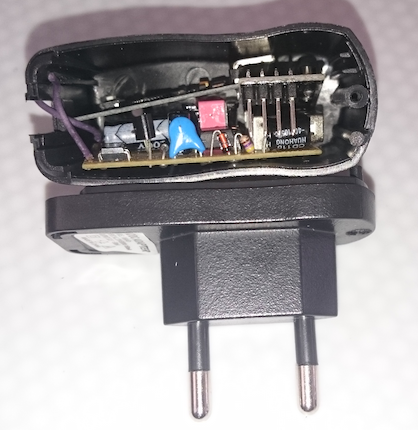
Before wirering everything up, I just added the smaller white's pcb to the black case incl. radio and pro mini. And there is room for a bit more.
So unless it goes up in flames I will try to create a default sensor node.
Can't remember the specs. "Normally" 3.3v is something like 3.0-3.6v..
Just did the google thingy.. 3v-5v:)
@dakky Well you can do the gateway for around $13ish and thats easy. Adding the gateway module to the running OpenHab could be easy if they can coexist. I have not done that, so again, it could be easy. But since you are just starting out, keep it easy.
And afterwards, you can reuse the uno for other projects..
OpenHab on a pi is a good choice.
I would use an Arduino Uno with an ethernet shield for the MQTT gateway, so much easier to setup.
A good 18650 3.7v battery should give you more than 6 months if you power trim you sensors.
And the transmission would be by using NRF24L01+'s.
So all about making it easy for yourself:)
So to answer you question.. Yes, should be easy to achieve fairly fast.
That lib only supports HW SPI(from what I can see) and I would need it for Pro Mini's. But tried it on a mega, almost same issue.
Did some more testing with same result. I checked the datasheets , and from what I can see, it is depending on a stabel reference voltage.
Was driving my pro mini with 5v and then regulating it to 3.3v for the MAX31855. So dataline was 5v and max31855 was 3.3. Even if this is within spec the macx31855 board I got was as cheap one, so it did not filter the voltage/data input for the chip.(Looks like the Adafruit board does?) Moving the regulator in front of it all, driving everything with 3.3v it's as stabel as could be expected.
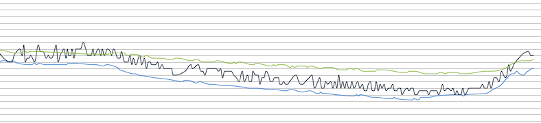
Green is a DS18B20, Blue a DHT21 and the black is the ThermoCoupler.
Nope, using the Adafruit.. Will try this !!