After 4 months of finishing the new house, i finally started to build in my sensors :)
Do need to build a new repeater, since a part of the sensors are out of reach.
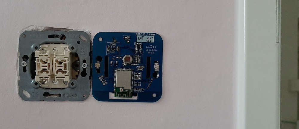
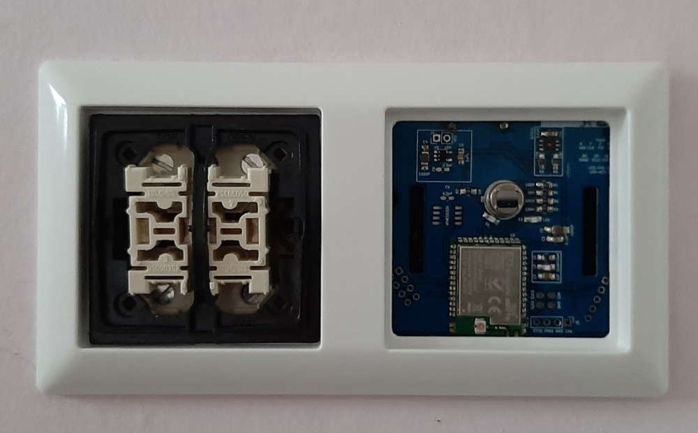
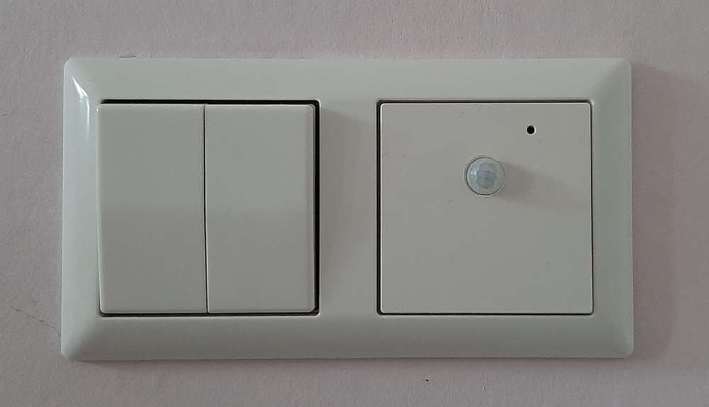
After 4 months of finishing the new house, i finally started to build in my sensors :)
Do need to build a new repeater, since a part of the sensors are out of reach.


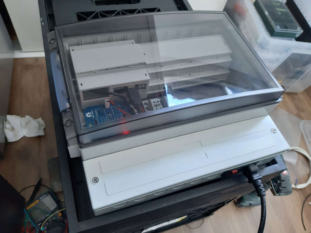
After months of slow painstaking work (day job is somewhat busy, o and the kids ;) ) I finally completed my Domoticz server(case) with Dashticz as frontend.
The Endgame; when my new house is finished every room is monitored for motion, RH and Temperature using my MySensors PCB's. (Jung AS500 Node)
Everything is monitored using a raspberry with a MySensors serial gateway (NRF52) and an RFLink controller for my KAKU switches.
To make everything nice and shiny I use Dasticz to interface the data in a proper way using a tablet that somehow will be mounted on a wall or something.
So far the introduction;
To put everything away nice and tidy I used a box to install everything using 2 pieces of din-rail.
It has a 230V inlet that is converted to 5V using an off the shelf (safety sake) MeanWell RS-15-5 converter. This powers everything using a couple of din-Rail terminals.
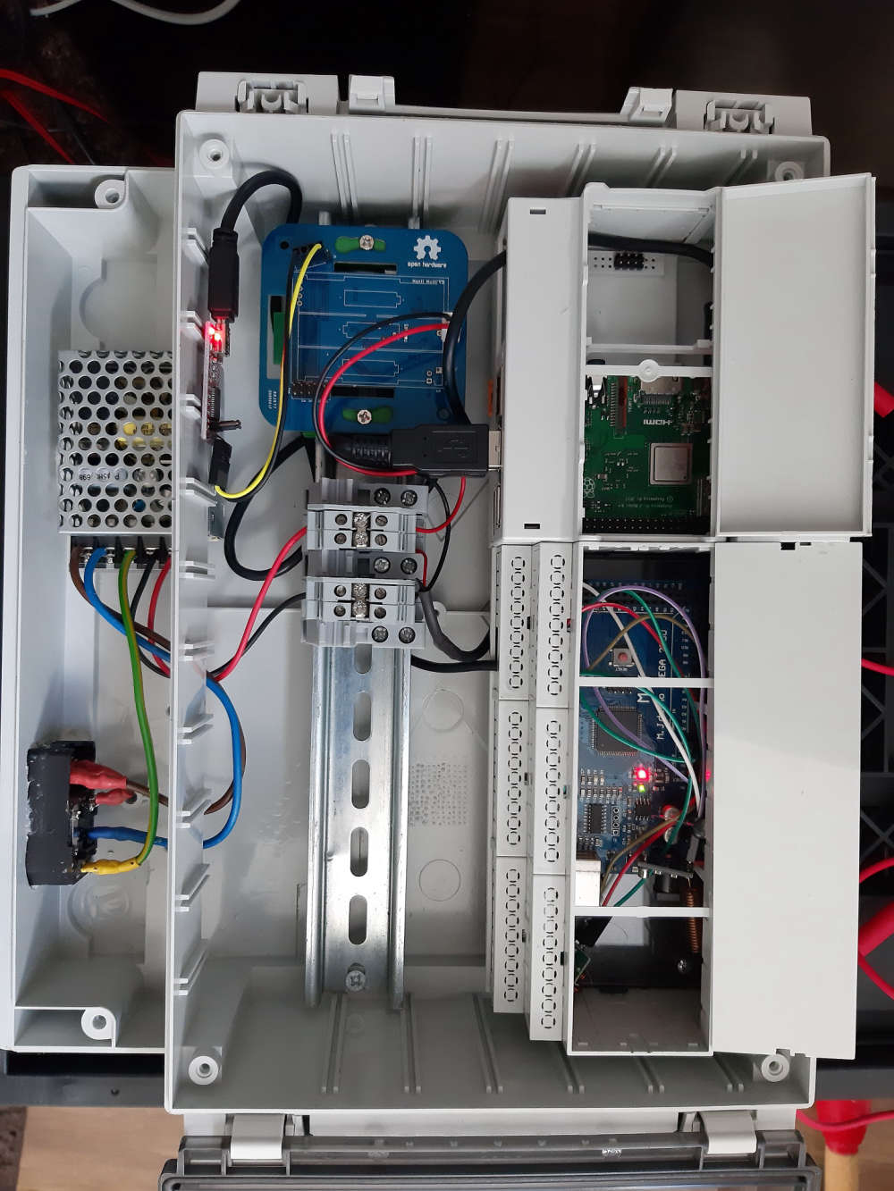
Since the Raspberry has Wifi no other cable then power is needed to operate
Second part: the 2 screenshots of dasthicsz.
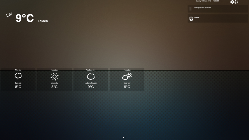
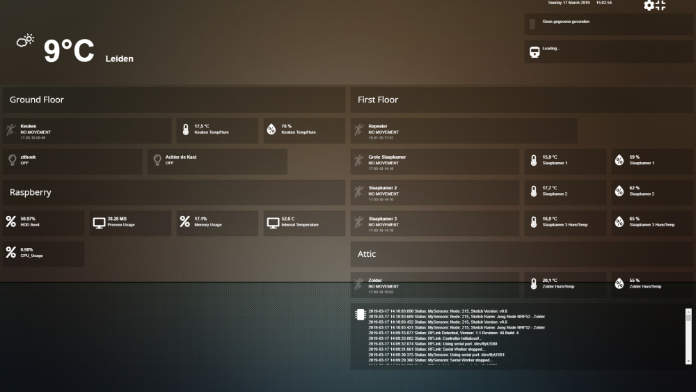
The best part, it took some work, but the WAF incread big time, because everything looks clean :)
For those who are, just like me, trying to switch form Eagle to KiCad.
I found : https://www.snapeda.com/parts/add/
You can upload Eagle parts etc, and convert them to their KiCad counterparts.
Its not flawless, as far as I can see it seems OK to give it a try.
For anyone interested, and to correct my mistakes, I just put up an NRF52 node that is powered by an off the shelf ac/dc converter to be used as a repeater node.. feel free to comment
https://www.openhardware.io/view/613/NRF52-Wall-Node-ACDC
This topic did most of the research for me, so thank you :)
Today I finally assembled some of my new PCB's
2 New front PCB's (a repeater and a LED-Dimmer)
1 New Back PCB that can be used as just an AC/DC power supply or as part of the AC current side of the LED-Dimmer
The last inwall repeater I made was just one PCB, and during installation, I got zapped :cry: , so I tried to make a 3D design to counter that.
The part that is the furthest in the wall is the AC side, and the microcontrollers, etc (DC-side) are at the front. Both are connected using 4 pins and are fastened by 4, 3m standoffs
I think this is much safer when, for instance, the front cover is taken off. (i use the same design as: LINK)
Pictures show the FL5150 dimmer at the front and its compatible backside.
When the testing is done, I also want to connect a touch sensor to it, so the dimmer can be controlled remotely as well by touch.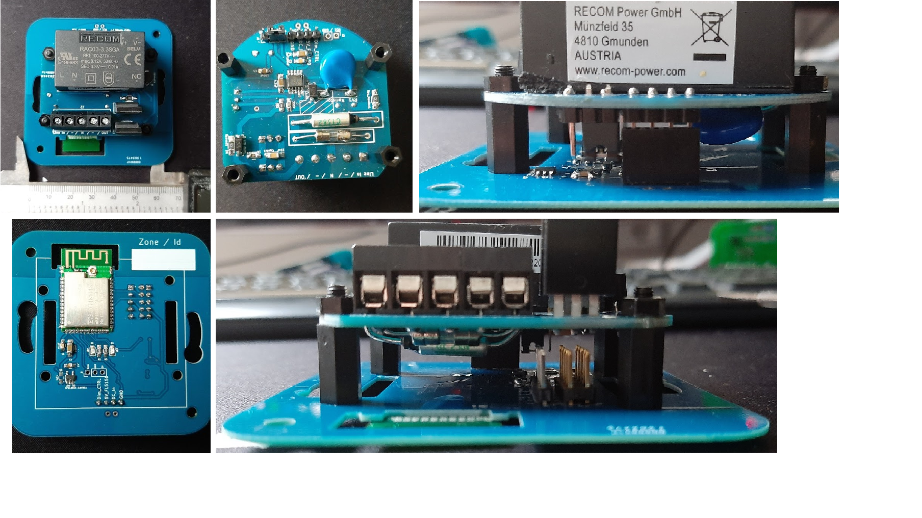
https://forum.mysensors.org/topic/6961/nrf5-action/1659
That fixed it.
@sundberg84 "well, it seems like I can only get KiCad to make 45dgr tracks"
References => General Settings => Limit graphics lines to 45 degrees
@neverdie it's the AM612, and in the little tests I did so far, it did great.
Here in the Netherlands, schools and daycares are closed for a week now, and stays so at least until the 6th of April. Only people with vital occupations can drop their kids off (hospital personal, and people who work for food companies etc. )
For the rest, they advise to stay at home and if you need to go out, stay at least 1,5m away from one another. No lockdown yet, they hope these measures will help flatten the curve.
But people are so very stupid atm. "hey its sunny, let's all go to the park/beach/(fill in crowded place)". I fear that for this reason, they will have a lockdown anytime soon.
@Nca78 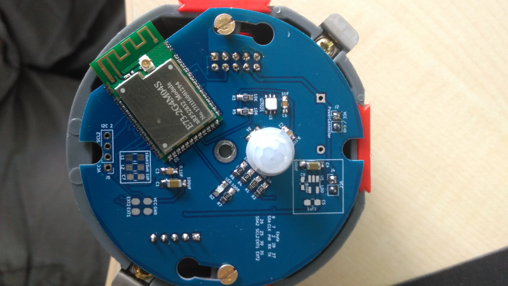
Getting rid of the ground plains around the entire module hugely improved the range. Had to stap back to AAA batteries to fit on the board. But I'm happy with the way it's going (AA is still possible but not soldered on it just doesn't fit enough in the wall socket)
@maciekczwa said in nRF5 action!:
Licensed under GNU GPL v2
For bug reports, read
http://openocd.org/doc/doxygen/bugs.html
debug_level: 2
0x4000
Info : The selected transport took over low-level target control. The results might differ compared to plain JTAG/SWD
adapter speed: 10000 kHz
Info : Unable to match requested speed 10000 kHz, using 4000 kHz
Info : Unable to match requested speed 10000 kHz, using 4000 kHz
Info : clock speed 4000 kHz
Info : STLINK v2 JTAG v17 API v2 SWIM v4 VID 0x0483 PID 0x3748
Info : using stlink api v2
Info : Target voltage: 3.241270
Info : nrf52.cpu: hardware has 0 breakpoints, 2 watchpoints
Error: timed out while waiting for target halted
TARGET: nrf52.cpu - Not halted
in procedure 'program'
in procedure 'reset' called at file "embedded:startup.tcl", line 478
in procedure 'ocd_bouncer'**embedded:startup.tcl:454: Error: ** Unable to reset target ****
in procedure 'program'
in procedure 'program_error' called at file "embedded:startup.tcl", line 479
at file "embedded:startup.tcl", line 454
wybrany port szeregowy at file "embedded:startup.tcl", line 454
maybe someone else already found the solution, but it took me a while to figure it out for myself.
So for documentation sake:
Just had the exact same things with new Ebyte NRF52832 modules, ST-Link v2 couldn't erase it. (the old once did erase without a single problem )
After some digging, I found the following:
(I'm using my NRF52832-DK for it, maybe other devices work as well, just tested this one)
DK => Ebyte module
GND(detect) => GND
SWDIO => SWDIO
SWDCLK => SWCLK
VTG => 3,3V
3,3V => 3,3V
GND =>GND
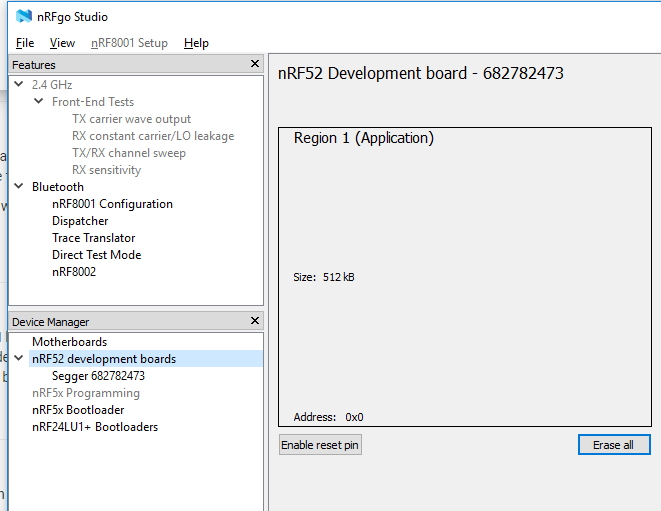
you can erase the protection using nRFgo Studio
@gohan said in Help: Some explanation requested regarding NACK:
the node can't receive the ack message so it assumes it's lost: could the the gateway did
mjah, ofcourse,
Well I'll build me some more of these, see If the same things happen with some other nodes.
thnx for the help so far!
@mfalkvidd oké, clear!
Unfortunate.
Guess a couple esp8266 couldn't hurt. 😀
@NeverDie said in nRF5 Bluetooth action!:
From the view count, it does seem that people are reading this thread, even if not many are posting.
I follow your journey with great interest, one day Ill find the time to do something with it :)
Hey, Welcome,
If you just want to get started, prepare for some trial and error (that's almost half the fun if you ask me :)).
I suggest you start with a serial monitor and use myscontroller as a controller.
If you ask me this is the easiest way to test if everything is working.
when you are confident on your progress, hook up a wifi gateway and link that to whatever you like (I only have experiences with domotics + dachticz in combination with a wifi-gateway ( ESP8266+NRF52832))
@neverdie, Indeed, I checked and it was false. well goes to show that late-night prototyping has some disadvantages, my bad, :)
Deleted Following up question..
DK =>Ebyte module
GND(detect) => GND
SWDIO => SWDIO
SWDCLK => SWCLK
VTG => 3,3V
3,3V => 3,3V
GND =>GND
Does this give me more information compared to the normal #MY_DEBUG? Skip that, had to change things in MyConig.. lets see what happens
to be complete; I used: #define MY_DEBUG_VERBOSE_NRF5_ESB
@sundberg84 that board looks nice and crisp 👍
@gohan LOL, i need to stop buying these things, got 12 just waiting to be used.. but at this price, its almost impossible to not buy them :)