@waspie said in High power consumption NRF52832 & SI7021:
1455 is the latest and greatest
so would it be a good idea to flash all my nodes? got 10 laying around..:)
@waspie said in High power consumption NRF52832 & SI7021:
1455 is the latest and greatest
so would it be a good idea to flash all my nodes? got 10 laying around..:)
After a year of nearly having no problems, I got nodes that started crashing.
I let my repeater up for the night and monitored his behavour.
I got this again:
08:47:27.607 -> 22440 NRF5:SND:TO=0,LEN=16,PID=0,NOACK=0
08:47:27.641 -> 22447 NRF5:SND:END=1,ACK=1,RTRY=2,RSSI=-45,WAKE=8
08:47:27.641 -> 22452 TSF:MSG:SEND,78-78-0-0,s=1,c=1,t=0,pt=7,l=5,sg=0,ft=0,st=OK:24.3
08:47:27.707 -> 22508 NRF5:SND:TO=0,LEN=16,PID=1,NOACK=0
08:47:27.707 -> 22515 NRF5:SND:END=1,ACK=1,RTRY=2,RSSI=-45,WAKE=7
08:47:27.707 -> 22520 TSF:MSG:SEND,78-78-0-0,s=0,c=1,t=1,pt=7,l=5,sg=0,ft=0,st=OK:45.2
08:47:28.435 -> 23226 NRF5:SND:TO=0,LEN=16,PID=2,NOACK=0
08:47:28.435 -> 23233 NRF5:SND:END=1,ACK=1,RTRY=2,RSSI=-45,WAKE=7
08:47:28.435 -> 23237 TSF:MSG:SEND,78-78-0-0,s=2,c=1,t=16,pt=1,l=1,sg=0,ft=0,st=OK:1
08:47:28.766 -> Si7021 Found
08:47:29.331 -> 24145 NRF5:SND:TO=0,LEN=16,PID=3,NOACK=0
08:47:29.331 -> 24152 NRF5:SND:END=1,ACK=1,RTRY=2,RSSI=-45,WAKE=7
08:47:29.331 -> 24157 TSF:MSG:SEND,78-78-0-0,s=1,c=1,t=0,pt=7,l=5,sg=0,ft=0,st=OK:24.3
08:47:29.397 -> 24213 NRF5:SND:TO=0,LEN=16,PID=0,NOACK=0
08:47:29.397 -> 24220 NRF5:SND:END=1,ACK=1,RTRY=2,RSSI=-45,WAKE=7
08:47:29.397 -> 24225 TSF:MSG:SEND,78-78-0-0,s=0,c=1,t=1,pt=7,l=5,sg=0,ft=0,st=OK:45.2
08:47:32.310 -> 27131 NRF5:SND:TO=0,LEN=16,PID=1,NOACK=0
anyone got an Idea what this message means,
it crashes after the last line.
@mfalkvidd for the thing I'm working on, I'd like to pass this string into another function. Do know how I can get this information into a variable? Preferably char[].
Hey,
maybe someone can help me out easy on this.
I got a gateway, and just want to print the message that comes in into a serial monitor. (or maybe strip it down the road)
Is there an easy way to just serial print a message like: 219;2;1;0;16;1. Instead of having the debug doing it.
Here in the Netherlands, schools and daycares are closed for a week now, and stays so at least until the 6th of April. Only people with vital occupations can drop their kids off (hospital personal, and people who work for food companies etc. )
For the rest, they advise to stay at home and if you need to go out, stay at least 1,5m away from one another. No lockdown yet, they hope these measures will help flatten the curve.
But people are so very stupid atm. "hey its sunny, let's all go to the park/beach/(fill in crowded place)". I fear that for this reason, they will have a lockdown anytime soon.
Hey all,
I want to upgrade my system to be able to use MQTT.
ATM, I'm using a ESP8266 (ESP-link) with an Ebyte NRF52832 as a mysensors gateway (LINK)
Can anyone point me on how to achieve this.
So my goal is:
Let all my NRF52832 mysensor nodes report to an MQTT broker (preferably bound to an ESP8266)
Who can point me in the right direction, or even better, tell me how to achieve this.
This is amazing, and comes at the right time!
I just finished my kitchen and forgot to put a neutral line in for my remote switch.
This sounds very promising.
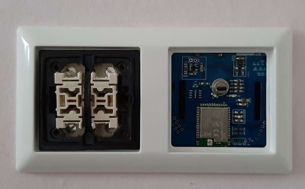
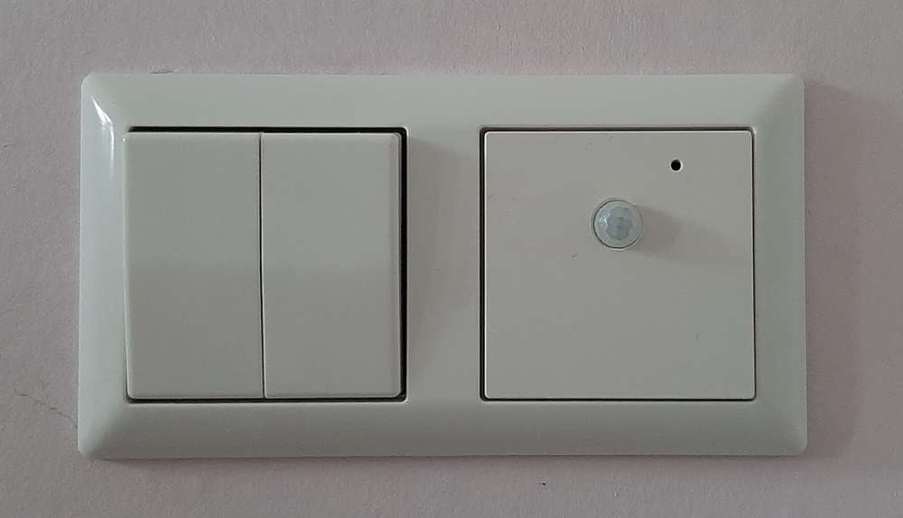
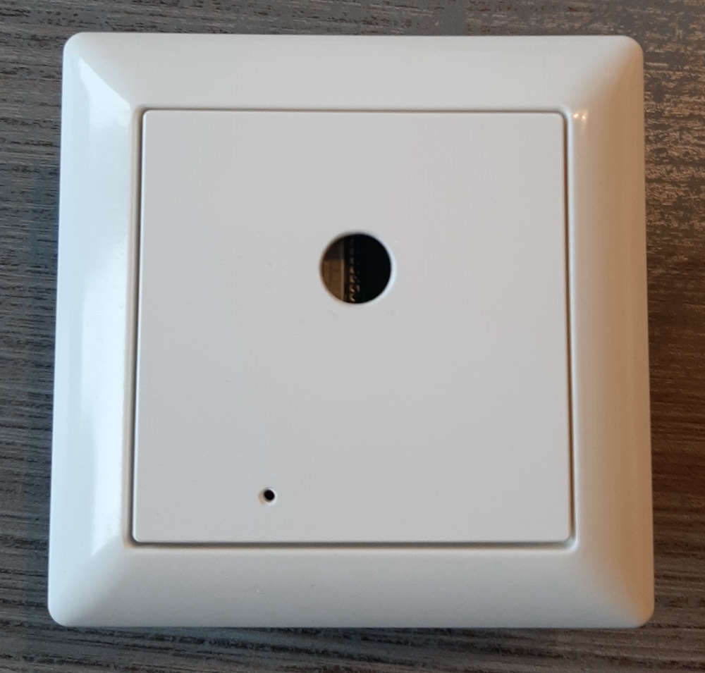
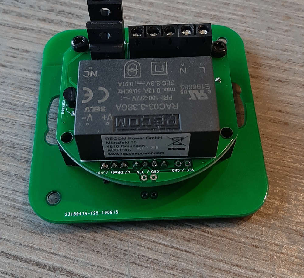
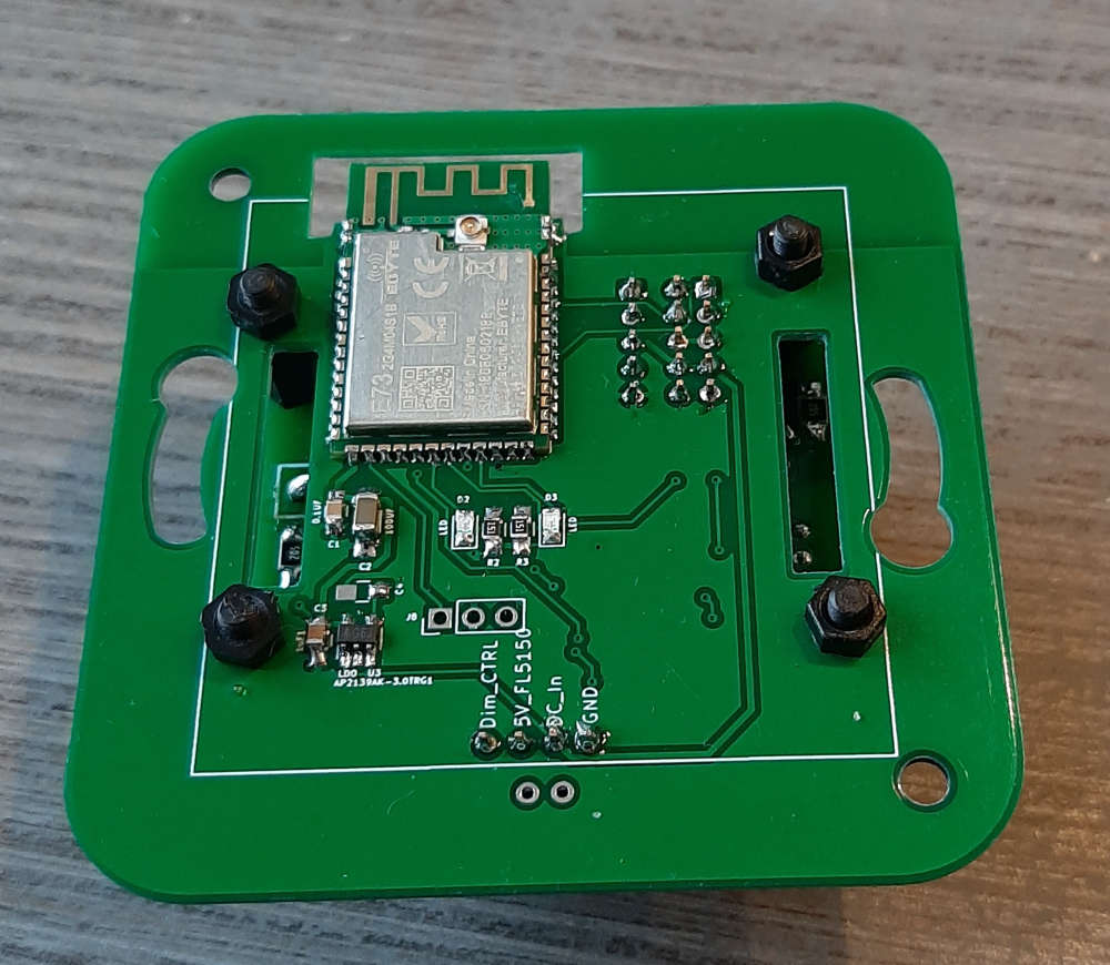
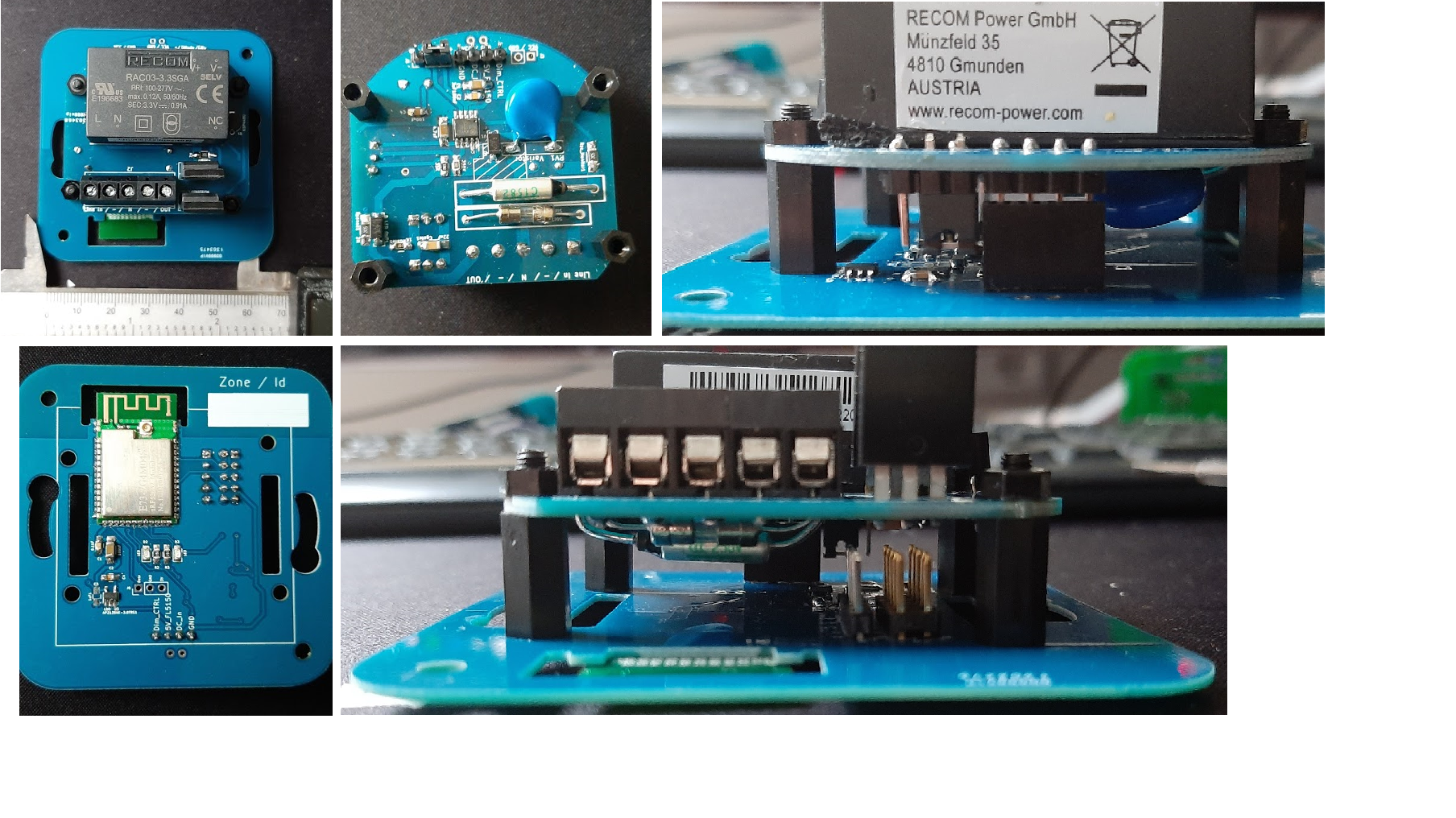
Today I finally assembled some of my new PCB's
2 New front PCB's (a repeater and a LED-Dimmer)
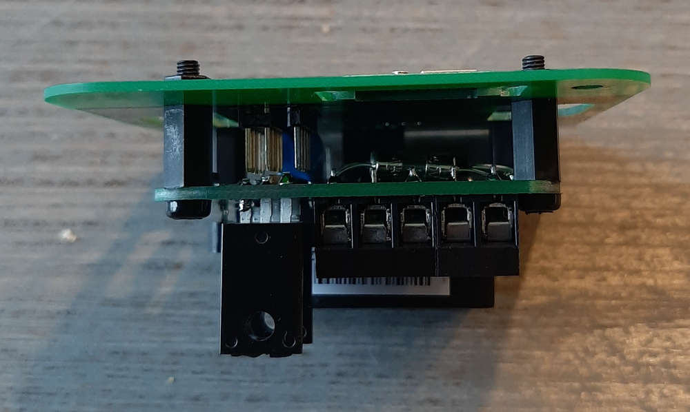
1 New Back PCB that can be used as just an AC/DC power supply or as part of the AC current side of the LED-Dimmer
The last inwall repeater I made was just one PCB, and during installation, I got zapped , so I tried to make a 3D design to counter that.
The part that is the furthest in the wall is the AC side, and the microcontrollers, etc (DC-side) are at the front. Both are connected using 4 pins and are fastened by 4, 3m standoffs
I think this is much safer when, for instance, the front cover is taken off. (i use the same design as: LINK)
Pictures show the FL5150 dimmer at the front and its compatible backside.
When the testing is done, I also want to connect a touch sensor to it, so the dimmer can be controlled remotely as well by touch.
@kiesel said in Help: Some explanation requested regarding NACK:
e you able to solve this? I am also experiencing a lot of NACKs in my rfm69 network (868mhz)
Nope, not that I can remember.
BTW: I ditched the rfm69 and moved over to the NRF52.
@nagelc Its al from jung. Series AS500. Its hard for me to search for sellers in the US.. Google forces me to search in the Netherlands.
My understanding that the standard inwall boxes in North America are pretty different than in Europe /Netherlands . The types I use always look like this
But I'll share my kicad files on openhardware.io, only thing you have to do is change the backplate.
This sensor : link
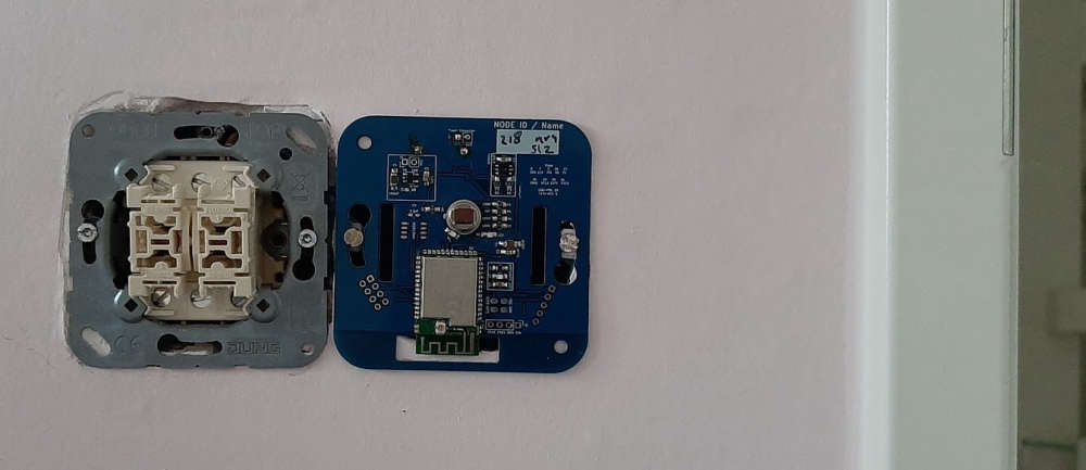
Also made a repeater, but this one is fairly unsafe( I got zapped installing it ). I just got the PCB's for a safer version I hope I can post pictures when everything works.
After 4 months of finishing the new house, i finally started to build in my sensors
Do need to build a new repeater, since a part of the sensors are out of reach.
@jimmyjames said in Question: FL5150 LED Dimmer - replace a analog potentiometer with a digital one:
a great looking design you've made there it looks very g
Thnx,
yesterday I finally installed my things after 2 months of moving. Going to try and make a new PCB using a NRF52 and the DAC you used. hopefully it will finally succeed to make a safe inwall socket.
I use a MCP4017T digital pot. the 50K one. I tested it, it worked. the dimming range isnt that great, but i think I have between 10% and 75% . To turn it off I have a mosfet to pull the DIMcontrol to GND and a mosfet to let DIMcontrol float (full on).
since the range that I have is limited, im curious how the DAC will operate.
When I look at the schematic from @jimmyjames, I see that he uses the mcp4716a0t-e/ch as DAC.
@jimmyjames Cool, I tried a DAC, but since my inexperience, I didn't get it to work with the FL5150.
I just received the PCB's I ordered and use a 50K digi-Pot. But now I want to use the DAC..
Sofar:
it's been a while. A short status update. I made a PCB and I'm testing the principals, but since I lack the time it will take a couple of months more .
First impressions, I can control the chip with a digital potentiometer. I use a 100K for dimming, and pull it to ground for shutdown.
The 100K pot cost a couple of cents. Preferably you would use a 250K but those cost around 9 euros.
I made some new PCB's for testing, I made some booboos with the first tests. But as I said, I'll be busy the next couple of months.
Since the dimmerpin needs a resistor to ground. I placed a 1M ohm digital potentiometer and used it to controll the dimmer. so far it works (a bit).
1M ohm is to much, so maybe I can get is working with just one or two 100k ohm.
I solderen together a very rough setup, and I can dim the light using a pro-mini 3,3v.
It still has some flickering, and I think I need to get a MOSFET or something to pull it to ground to turn the light off.
But so far so good.
@nagelc just bought some things to get me started, I have a fallback, just use digital resistors, in series, if needed.
After reading the datasheet again, im not so sure the DAC will do the trick, it's the pull-down resistors that determine the voltage, so I think a DAC won't work.
@omemanti i did some digging, looks like a DAC will solve my problem. If it works I'll close this request. Fingers crossed.
Hello,
I need some help,
I'm trying to figure out how to build a remote led dimmer.
Now I saw great Scott, and he build one with an FL5150.
I thought this would be a chance to combine it with an nrf52 module that I use for my other nodes.
The question is, can I replace the potentiometer with a digital one.
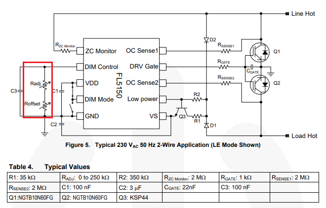
I looked at a AD5241BRZ1M it has 256 steps from 0 to 1mio (it only needs 0 to 250 though, but the 200ohm seems to be too little, correct me if I'm wrong and the 250ohm are too expensive to my liking.
Or is there another way of doing this?
thnx!
@olision said in Choosing the right NRF chip for MySensors:
think the only advantages choosing a nrf52840 over the nrf52832 is the range according to the spec sheets and the possibility to connect a LiPo battery directly without using a voltage regulator. On that later, is it more energy efficient to use the LiPo battery directly than using an external LDO?
Has anyone tried those chips on a MySensor sketch or built their own sensors using those chips? Any other recommendations or one I should go with for my custom PCB?
Thanks for your help making that component choice!
hey,
I don't think the NRF52840 is working with MySensors yet.. But I don't know what happened in de last months on the development side. I believe @NeverDie was working with those chips in combination with micropython.
I personally stuck with the NRF52832, I have a couple of nodes working with Ebyte modules. It suits my needs and I stockpiled some modules for future projects.. Just browse openhardware.io and you can find a couple of examples. @berkseo made also some things you want to take a look at.
@nca78 I don't use ATAES132A. I put it in just in case I wanted to invest some more time using it.
I now just use SimpleEncryption, it's secure enough for my purpose atm.
(since the area I live in uses KAKU a lot, an insecure 433MHz lightswitch, I don't think anyone would be bothered to hack my temperature sensors. I found 163 433Mhz devices when I left domoticz logging for a couple of days.)
If someone would be interested:
Enclosure
Ard. Mega enclosure
Raspberry enclosure
Had to do some modifications for the mega, but the cost of this enclosure was more than worth it.
Hmz.. normaly don't buy stuff at conrad but apparently they have good prices on cases...
@canossa Sorry for the late response.
yeah, since is so compact and you can get it for relatively cheap I opted in for the NRF52.
For home automation, I merged MySensors with Domoticz and it works for months now.
https://forum.mysensors.org/topic/7836/what-did-you-build-today-pictures/738
@kisse66 have you reset it (on/off) after uploading it uses to much power, but after a reset, it drops. my modules drop to 30uA or something. So it should be possible to hit a low powerconsumption.
After months of slow painstaking work (day job is somewhat busy, o and the kids ) I finally completed my Domoticz server(case) with Dashticz as frontend.
The Endgame; when my new house is finished every room is monitored for motion, RH and Temperature using my MySensors PCB's. (Jung AS500 Node)
Everything is monitored using a raspberry with a MySensors serial gateway (NRF52) and an RFLink controller for my KAKU switches.
To make everything nice and shiny I use Dasticz to interface the data in a proper way using a tablet that somehow will be mounted on a wall or something.
So far the introduction;
To put everything away nice and tidy I used a box to install everything using 2 pieces of din-rail.
It has a 230V inlet that is converted to 5V using an off the shelf (safety sake) MeanWell RS-15-5 converter. This powers everything using a couple of din-Rail terminals.
Since the Raspberry has Wifi no other cable then power is needed to operate
Second part: the 2 screenshots of dasthicsz.
The best part, it took some work, but the WAF incread big time, because everything looks clean
@sundberg84 that board looks nice and crisp
@nagelc I also use normal interrupts. No problems here. Up to 22uA while sleeping, that's fine by me. (3 AAA will last a long time)
@waspie you might want to look at one of my projects on openhardware. It has a sketch on it. It also uses the am612
A quick Google pointed me to https://github.com/AndruPol/nrf52832-recover/blob/master/README.md
I do have a STM32F103C8T6 laying around. But ATM no time to play with it.
Maybe that's the €3 solution for unlocking.
@smilvert do you have some more information? like some serial output?
I had some issues with statements that uses millis(), in about 1,5 up to 2 days (much shorter the normaly I suppose) it did its rollover back to 0. This messed some waiting times for me.
FYI:
Yesterday I tried to use the MY_ENCRYPTION_SIMPLE_PASSWD and SIGNING (so not MY_SECURITY, everything separate), the gateway also crashes after a couple of hours.
So reverted all my sketches and now only have MY_ENCRYPTION_SIMPLE_PASSWD on all my nodes. Since that time I've been receiving everything and had no crashes.
I posted a Log of the gateway from boot (around 2 hours ago) to last crash.
https://github.com/Omemanti/Paste/blob/master/Gateway_log_01-01-2019_security.txt
everything seems normal (to me) except de crash in the end.
@anticimex said in Nrf52 gateway crashes:
@omemanti it is not clear from your message what actually happened. Did something stop working?
like posted a month ago; it "sometimes" stops working at the following line:
0;255;3;0;9;759816 TSF:MSG:READ,215-215-0,s=2,c=3,t=16,pt=0,l=0,sg=1:
0;255;3;0;9;759818 NRF5:SND:TO=215,LEN=32,PID=2,NOACK=0
All nodes in the network are sending in data every 5 to 10 minutes (depending on the node) it all runs smoothly up until the line like above comes around. So all nodes send data and are using the same password etc.
All went oke when I changed to only encryption, when I went back to security it starts breaking again.
Average time form rebooting the gateway up until crashing averages from 30 minutes up until 15 hours. (yesterday I rebooted the gateway at 8:00 and it stopped working at 23:30)
A month ago, I changed my sketch.
I replaced "MY_SECURITY_SIMPLE_PASSWD" to "MY_ENCRYPTION_SIMPLE_PASSWD" because this was most important to me. Nothing bad happened, I received everything in perfect order.
for the sake of testing, I switched back to "MY_SECURITY_SIMPLE_PASSWD" a couple of days ago, Guess what is happening since that time.
So there are to options to consider, or the implementation of MY_SECURITY_SIMPLE_PASSWD has a bug, or the Simple Signing is messing with my gateway.
Can you tell something about the range of this node?
And do you see a chance to post the schematic?
@ileneken3 sorry, can't help you anymore.
I can only tell that I installed the segger drivers, and everything as described by @d00616
Most issues I have, happen when I did some soldering wrong or when I've been messing around with drivers. A clean setup almost always solve my problems
I used both old and new ebyte modules and they work like a charm.
the difference between E73-2G4M04S and E73-2G4M04S1B is that the last one seems to be from a new batch. I got both, the only difference was that the last one I needed to recover and the other one (old) I only had to "burn bootloader".
your problem with the Arduino IDE seems to have something to do with the Sandeep installation, see the comment of @Toyman: https://forum.mysensors.org/topic/6961/nrf5-action/1749
@ileneken3 Have you considered building a new gateway with a nrf52?
You know now that the IDE is programming correctly. Try combining a ftdi and nrf52 to get a serial gateway.
Also I would hook up the gateway and prototype board to a serial monitor. ( So both boards onto my PC)
You can both monitor the node and the gateway directly from the RX and use https://www.mysensors.org/controller/myscontroller to act as controller.
I find it handy to cut out things like domoticz when troubleshooting (the less variables the better)
@ileneken3 1. how did you wire the DK tot the target module?
https://forum.mysensors.org/topic/6961/nrf5-action/1744
FYI, I both use the stlink and nrf52832-DK for programming. And I'm pretty sure the stlink I use is not so original. 2 dollar each.
@rozpruwacz o really, yeah me I guess .
I'm on my phone atm, but a similar sketch should be in my openhardware.io projects. (Have been playing around with it, but those where minor changes)
@rozpruwacz seems about what I get aswell. I get 18 /19 uA on my boars with a si7021 and am612 PIR sensor.
However, I have not yet looked at lowering this for instance with dc/dc mode.
Also I don't know what and how a wdt (really don't have a clue how to use it) would work and impact the consumption.
But all things considered, my nodes are powered with 3 AAA batteries, that would take it past 5 years.
@spanners to give you some assurance about these modules, I programmed 15 units by now, eventually all were working at the end.
Upload looks fine indeed,
I'm not sure if they hang, I just think the pinout wasn't right.
Whenever Pins are not working correctly I check the files again (to be sure), then close down the Arduino IDE. And open the sketch you want to upload. somehow it looks like the pinout isn't coming through correctly when a different version is also opened.
@berkseo great, I'm going to try it soon, I have 5 nrf52832 chips laying around (got them with the nrf52832-DK). Would be a shame if I didn't use them
Great work, this looks interesting.
How did you solder the nrf5? Can you also put in a schematic in PDF?
tonight, I let a node send data to the gateway, this one hangs after a couple of hours, but this time, I also hooked up an FTDI to the node, to have some readout as well from it.
It also broke down at the same stage like all the others did:
45381108 TSF:MSG:SEND,215-215-0-0,s=1,c=1,t=0,pt=7,l=5,sg=1,ft=0,st=OK:13.3
45381165 NRF5:SND:TO=0,LEN=32,PID=1,NOACK=0
Why would it always hang on that this same line?
-- while operation, the node stays at a solid 3,0 V during all operations.
ill take a look at it, yup, a 100nf and 100uf next to the nrf52832. One setup had a 470uf for good measure..
It an assumption but I guess so, its an ST-Link V2 as power for the Ebyte module.
I use it to test my nodes with. So far none broke down.
The Weemos has its own USB power
I've been troubleshooting for the last couple of days now;
so far:
2 things that came up "positive"
I don't know if it makes any sense, but when I combine the weemos with a nrf52832 (using Serial Gateway) is get bumps in the road. separate they work like charm.
every time it crashes, it at this line:
0;255;3;0;9;1268917 NRF5:SND:TO=216,LEN=32,PID=0,NOACK=0
The "good" part, it happens to all nodes.
Could it have something to do with power? because the next line should be also an "SND"
Or can it be an encryption thing, that it happens before the SND part?
i got 3 crashes, every one of them happened within the 20 minutes:
all ended like:
0;255;3;0;9;759816 TSF:MSG:READ,215-215-0,s=2,c=3,t=16,pt=0,l=0,sg=1:
0;255;3;0;9;759818 NRF5:SND:TO=215,LEN=32,PID=2,NOACK=0
the strange part, its now node 215 instead of 114, both are located in a room somewhat distance from the gateway
average communication looks like:
0;255;3;0;9;750507 NRF5:RX:LEN=32,NOACK=0,PID=0,RSSI=-34,RX=0
0;255;3;0;9;750508 TSF:MSG:READ,216-216-0,s=0,c=3,t=16,pt=0,l=0,sg=1:
0;255;3;0;9;750510 NRF5:SND:TO=216,LEN=32,PID=1,NOACK=0
0;255;3;0;9;750514 NRF5:SND:END=1,ACK=1,RTRY=1,RSSI=-35,WAKE=5
0;255;3;0;9;750515 TSF:MSG:SEND,0-0-216-216,s=255,c=3,t=17,pt=6,l=25,sg=1,ft=0,st=OK:<NONCE>
0;255;3;0;9;750535 NRF5:RX:LEN=32,NOACK=0,PID=1,RSSI=-34,RX=0
0;255;3;0;9;750537 TSF:MSG:READ,216-216-0,s=0,c=1,t=1,pt=7,l=5,sg=1:60.9
Does this give me more information compared to the normal #MY_DEBUG? Skip that, had to change things in MyConig.. lets see what happens
to be complete; I used: #define MY_DEBUG_VERBOSE_NRF5_ESB
@electrik yup, switche the esp. I use esplink, and when the gateway crashes I can still reach the web-interface. So my guess is that the nrf is the problem, it somehow crashes or refuses to send/read data through the RX/TX.
It just crashed again: same node..
0;255;3;0;9;11077691 TSF:MSG:READ,114-114-0,s=0,c=3,t=16,pt=0,l=0,sg=1:
Hey There,
Something annoying is happening;
My setup:
a nrf52832+ ESP8266 as a gateway.
Several nodes, all have a nrf52832. most run the same sketch, everything is fine with those.
However, there is one node that is throwing a curveball once in a while. I need to cut the power off the gateway to reset. (the nrf needs to get powered down I assume)
I've been working on it for a couple of days now but haven't found the answer yet, maybe some of you will.
The last2 lines of the 4 instances the gateway crashes;
0;255;3;0;22;2665656
0;255;3;0;9;2674632 TSF:MSG:READ,114-114-0,s=0,c=3,t=16,pt=0,l=0,sg=1:
216;0;1;0;1;67.6
0;255;3;0;9;10584601 TSF:MSG:READ,114-114-0,s=0,c=3,t=16,pt=0,l=0,sg=1:
216;0;1;0;1;67.0
0;255;3;0;9;2311492 TSF:MSG:READ,114-114-0,s=0,c=3,t=16,pt=0,l=0,sg=1:
216;0;1;0;1;59.4
0;255;3;0;9;11077691 TSF:MSG:READ,114-114-0,s=0,c=3,t=16,pt=0,l=0,sg=1:
Its node 114 that always does this, but sometimes all goes well. I have some good readings from it, so it seems that not every entry makes my gateway crash.
the sketch for this node is similar to: https://www.mysensors.org/build/temp and im using: MY_SECURITY_SIMPLE_PASSWD since a couple of weeks.
Can anyone tell me why this is happing?
Hey, Welcome,
If you just want to get started, prepare for some trial and error (that's almost half the fun if you ask me :)).
I suggest you start with a serial monitor and use myscontroller as a controller.
If you ask me this is the easiest way to test if everything is working.
when you are confident on your progress, hook up a wifi gateway and link that to whatever you like (I only have experiences with domotics + dachticz in combination with a wifi-gateway ( ESP8266+NRF52832))
@nca78 @rozpruwacz indeed the nrf52dk will cost you a bit more, but will save you the troubleshooting. It's all ready and setup, so you only need to worry about the software side.
I have one myself and I'm pleased I did buy one when I started this journey.
@just4-electronics In also using the setup(am612) from NeverDie, and I'm pretty pleased with it. I mapped an extra cap to the setup but that's just for my pease of mind.
@rozpruwacz it looks pretty workable for testing purposes. For a final product my choice is something lika fanstel or ebyte module. Those are just easier to get into smaller cases etc. (Just my personal preference)
@toyman yup, I tried that one, but all it kept saying was something like; can't find programmer.. and this method, which has a GUI, worked without incident
@maciekczwa said in nRF5 action!:
Licensed under GNU GPL v2
For bug reports, read
http://openocd.org/doc/doxygen/bugs.html
debug_level: 2
0x4000
Info : The selected transport took over low-level target control. The results might differ compared to plain JTAG/SWD
adapter speed: 10000 kHz
Info : Unable to match requested speed 10000 kHz, using 4000 kHz
Info : clock speed 4000 kHz
Info : STLINK v2 JTAG v17 API v2 SWIM v4 VID 0x0483 PID 0x3748
Info : using stlink api v2
Info : Target voltage: 3.241270
Info : nrf52.cpu: hardware has 0 breakpoints, 2 watchpoints
Error: timed out while waiting for target halted
TARGET: nrf52.cpu - Not halted
in procedure 'program'
in procedure 'reset' called at file "embedded:startup.tcl", line 478
in procedure 'ocd_bouncer'**embedded:startup.tcl:454: Error: ** Unable to reset target ****
in procedure 'program'
in procedure 'program_error' called at file "embedded:startup.tcl", line 479
at file "embedded:startup.tcl", line 454
wybrany port szeregowy at file "embedded:startup.tcl", line 454
maybe someone else already found the solution, but it took me a while to figure it out for myself.
So for documentation sake:
Just had the exact same things with new Ebyte NRF52832 modules, ST-Link v2 couldn't erase it. (the old once did erase without a single problem )
After some digging, I found the following:
(I'm using my NRF52832-DK for it, maybe other devices work as well, just tested this one)
DK => Ebyte module
GND(detect) => GND
SWDIO => SWDIO
SWDCLK => SWCLK
VTG => 3,3V
3,3V => 3,3V
GND =>GND
you can erase the protection using nRFgo Studio
@ileneken3 said in GUIDE - NRF5 / NRF51 / NRF52 for beginners:
hat - although without an led it’s hard to know if the board really is getting power. I will check with a multimeter.
did you use zadig to install the drivers for the ST-Link?
@reinhold I'm not sure if this helps, but I had 450uA drain when sleeping and shut down I2C everytime I'm done reading:
void i2c_off() // Shut i2c down, power consumption rises up to 450uA instead of 11 ua - https://github.com/sandeepmistry/arduino-nRF5/issues/291#issuecomment-407492282
{
NRF_TWI1->ENABLE=TWI_ENABLE_ENABLE_Disabled << TWI_ENABLE_ENABLE_Pos;
*(volatile uint32_t *)0x40004FFC = 0;
*(volatile uint32_t *)0x40004FFC;
*(volatile uint32_t *)0x40004FFC = 1;
}```
@neverdie would this also be usable for the nrf52832? (Not asking for an ETA here :))
@sundberg84 "well, it seems like I can only get KiCad to make 45dgr tracks"
References => General Settings => Limit graphics lines to 45 degrees
I see somewhat strange behaviour when using millis() for intervals.
I'm not sure it's my mistake, but one thing is that it seems that the millis rollover is around; 131.068.570 (36 hours)
When the rollover happens, it looks like it interrupts my sleep. Does that make sense?
sleep(digitalPinToInterrupt(PIR_Pin), CHANGE, LongSleep);
Debug lines => (Temp / RH - Millis)
21.44 / 61.15 - 130977952
21.43 / 61.16 - 131008158
21.42 / 61.15 - 131038364
21.44 / 61.14 - 131068570
I woke up because I saw movement at: 26576
Sleep Duration : -131042000 Im going back to sleep for 150000
21.43 / 61.16 - 176822
20-10-2018 => its been ±36 hours laters, and he woke up again at the same moment.
18.57 / 56.88 - 131007553
18.56 / 56.86 - 131037759
18.58 / 56.85 - 131067965
I woke up because I saw movement at: 25971
Sleep duration : -131042000 => Rollover??
18.55 / 56.89 - 206423
18.53 / 56.89 - 236628
18.54 / 56.90 - 266834
18.55 / 56.89 - 297040
18.54 / 56.90 - 327246
@xmonika I use the ST-Link, mine is always greyed out. The only time im able to select a port, it's when I'm using an FTDI to use the serial monitor. So I think everything looks normal.
@xmonika have you tried to erase it? In most cases if is start with a new module I first need to erase is once.
Shortcut => burn bootloader, this will give an error but you should be good to go from there.
@vladimir hey, but for safety reasons, how do you counter the fact that if there is no water in it, you just don't burn your house down. I did some quick calculations but the advantages of remotely setting the kettle on versus burning the house down, don't seem that favourable ;).
What are the options of getting OTA working? Is it supported? Or is it still work in progress? (If so, ia there an ETA?)
@nca78 yeah I noticed that, what is the downside of the NRF52810?
@neverdie well, July 2017 they were €4,15. So they went up around 1 euro in a year. FYI the last one I bought was about 5 months ago since then they went up from version 1,1 to 1,3.
Also, the item number changed a bit (but the datasheet checks out).
It went from E73-2G4M04S to E73-2G4M04S1B, and the introduced a nrf52810 E73-2G4M04S1A with the same footprint and pinout.
Not sure if it is allowed, else I remove this post, but the nrf52832's at ebyte are for sale (50% off)the coming 2 days.cdebyte AliExpress I sure grab myself some (max 2 at a time, but last time I ordered multiple times :)) only €2,62 a piece
Hey,
I got an issue with getting my custom board with SI7021 under 450uA.
I use the Sparkfun library to read data from it
I did some deductions.
When I insert sensor.begin(); it starts using quite an amount of power when sleeping.
When I remove this line it shoots down to around the 10ua.
I tried 2 board, that are identical, with exactly the same results
This happens also when I use this code on a board that doesn't have a SI7021 soldered onto it. So I don't think it is the SI7021.
SDA/SCL are both connected with a 10K pull-up.
My guess is that is has something to do with it being a thing with the NRF.
the readings from the SI7021 seem legit, so it works, but the sleep current wrecks my battery life.
Is there someone that can help me with this?
The same old story, when you finally go looking for help, you find your answer.
It indeed looks like it has something to do with the NRF52.
as mentioned: https://github.com/sandeepmistry/arduino-nRF5/issues/291#issuecomment-407492282
A workaround for the symptoms is known and described at:
http://infocenter.nordicsemi.com/index.jsp?topic=%2Fcom.nordic.infocenter.nrf52832.Rev1.errata%2Fanomaly_832_89.html&cp=2_2_1_0_1_26
Solution:
you need to add the following lines to shutdown the i2c:
NRF_TWI1->ENABLE=TWI_ENABLE_ENABLE_Disabled << TWI_ENABLE_ENABLE_Pos;
*(volatile uint32_t *)0x40004FFC = 0;
*(volatile uint32_t *)0x40004FFC;
*(volatile uint32_t *)0x40004FFC = 1;
And when you need some readings, just call "sensor.begin(); " to go on your way.
I measure 00.01 mA now, (multimeter doesnt go into the uA ranges )
Maybe @d00616, or someone else can work this into a standard routine (this is way out of my league, i can dump it into my sketch, but dont have a clue what it is doing)
Hey,
I got a question, I've built a PCB with a PIR-motion detector and a SI7021 temp/Hum sensor.
It all works great except for the power usage when the sensor is asleep.
Two scenarios happen, that I can't quite explain, but hopefully someone here can.
When I comment the "sensor.begin();" out it returns to 0.01mA.
schematic etc: https://www.openhardware.io/view/617/NRF52-Wall-Node-3-AAA
-- Might it be that is has something to do with it using a NRF52?
#define MY_DEBUG
#define MY_RADIO_NRF5_ESB
#define MY_NODE_ID 214
#include <MySensors.h>
#define SKETCH_NAME "PIR TESTING"
#define SKETCH_VERSION "v0.1"
int PIRLED = 29;
int ActLED = 6;
int PIR_pin = 2;
int a;
int b;
#include <Wire.h>
#include <SI7021.h>
SI7021 sensor;
void setup() {
Serial.begin(115200);
sensor.begin();
pinMode(PIRLED, OUTPUT);
pinMode(ActLED, OUTPUT);
pinMode(PIR_pin, INPUT);
}
void loop() {
sleep(5000);
a = digitalRead(PIR_pin);
Serial.println(a);
delay(500);
}```
For anyone interested, and to correct my mistakes, I just put up an NRF52 node that is powered by an off the shelf ac/dc converter to be used as a repeater node.. feel free to comment
https://www.openhardware.io/view/613/NRF52-Wall-Node-ACDC
This topic did most of the research for me, so thank you
Is it possible, or will it be possible to build a combination between wired and wireless nodes?
@Nca78
Getting rid of the ground plains around the entire module hugely improved the range. Had to stap back to AAA batteries to fit on the board. But I'm happy with the way it's going (AA is still possible but not soldered on it just doesn't fit enough in the wall socket)
Hey, sorry, I'm not familiar with your error messages.
Can you please sum everything up what you did so far and what your setup looks like (pic)
just to retrace your steps ( It might be useful to post it in a separate topic to keep this one cleaner ) => https://forum.mysensors.org/category/5/troubleshooting
@alowhum said in nRF5 Bluetooth action!:
@Omemanti I didn't realise the nRF52-DK was a hardware device. I thought it was a software program.
The nrf52 dev kit= > NRF52 Dev kit
To connect the DK to a module :
DK Ebyte module
GND(detect) => GND
SWDIO => SWDIO
SWDCLK => SWCLK
VTG => 3,3V
3,3V => 3,3V
GND =>GND
select J-link and there you go.
On the picture you provided (thanks!), are pin 6 and 8 connected to a serial port to read what's going on?
I used Pin 6 and 8 to connect to a FTDI to read out the serial. Since you can tell the sketch where to put the RX and TX I just connected them to 6 & 8.
Your ground is connected in a different place than mine (I connect it next to the VCC pin).
the Ebyte module has multiple GND connections, I messed the one next to the VCC up so I connected them next to the antenna. Just because I was easy
I suspect both those side-pins near the antenna, at the top, where you have soldered something, are ground too, right?
Indeed!
@alowhum by programmer you mean in something like the Arduino ide? That's what I use ( I both use the nrf52dk =>j-link aswell the st-link v2 => st-link)
@alowhum
maybe a very stupid question, but did you check all the wires and after that if your computer uses the right drivers.
I took me quite a while to figure this out myself. Especially the driver part messes things up. Errors everywhere that referred to different problems, but after I used Zadig they all disappeared.
For uploading code onto the Ebyte modules I use an ST-Link V2 (2 dollar USB modules).
Install the USB-Driver using Zadig
Connect the DIO, CLK VCC, and GND.
For testing purposes, I soldered just the tips of some Dupont cables to the Ebyte module and put the female parts on the ST-link.
The first time I want to upload code, I first "burn the bootloader" (Tools => burn Bootloader) (https://forum.mysensors.org/topic/6961/nrf5-bluetooth-action/386)
This will give an error.
After that, you should be able to upload sketches.
@neverdie it's the AM612, and in the little tests I did so far, it did great.
@nca78 I'm trying to create a node that fits inside a standard wallsocket. (I'll post it when it's done) it got a motion and moisture sensor.
For the next version I'm moving the module more to the outside but I need to take the screwholes into account.
The groundplane I used filled the entire PCB, next one will have less ground around the antenna or even holes.
It's designed to hold 3 AA batteries to have a couple years of service.
But cutting away that spot around the antenna gave me reception throughout the entire house
@neverdie said in nRF5 Bluetooth action!:
, that makes sense. That's why on my PCB's I have the antenna portion of the module hanging over the edge of the PCB into e
yeah, next one will be a big hole in the middle, lets see how that will work out..
@neverdie, I did some digging and cut a part of my PCB that was grounded. range drastically increased, guess I need to order a new prototype
Is there a way to enhance the sending performance of the Ebyte units?
I got a gateway that's sitting upstairs when I connect an Ebyte module I must be right underneath the gateway to let it receive packages.
When I do exactly the same same thing with an NRF52832-DK It doesn't matter where I'm standing, every message is received by the gateway.
Hey,
somehow I cant change the pins on my Ebyte module. Im trying to test with MockMysensors.
I want te TX set to pin nr. P0.06
I changed: MyBoardNRF.h and included nrf.h
#define PIN_SERIAL_RX (8)
#define PIN_SERIAL_TX (6)
but somehow the TX pin stays P0.25.
Can someone point me in the right direction?
The node connects to the gateway, so thats also working.
Seems like that if you put the MyBoardNRF5 files into the example map and you change some things in that file using the Arduino IDE, it doenst get uploaded. When I changed the MyBoardNRF5 file using Brackets it working as intended.
@shodney i used this one for a couple of tests. I resoldered the caps near the top and connected a new antenna. Works pretty well for testing purposes. I expect some pcb's a week ago for some further testing.
@koresh https://www.openhardware.io/view/420/AM612-Passive-Infrared-Sensor-Breakout-Board
But they all are THT so if you need smd it's a nono
@Koresh Why did you choose this PIR sensor?
I'm experimenting with an AM612 and works well for as far as I can tellen (is THT though).
Do you know if there is a difference in performance compared to the "standard" PIR sensors you get on eBay for 1 dollar?
hey,
anyone have experience with:
https://nl.mouser.com/ProductDetail/RECOM-Power/RAC01-05SGB?qs=sGAEpiMZZMuWiaalG5TUgCAeS4T2q9hep7l40%2FsKBt80J%2brWHE6eLg%3D%3D
It looks affordable and more regulated than the Chines modules.
some other variations: https://nl.mouser.com/RECOM/Power/Power-Supplies/AC-DC-Power-Modules/_/N-dv0g5?P=1yx5k7vZ1yzk8kkZ1yxt78rZ1yxt794Z1yxt791&Ns=Pricing|0
@yveaux jup, both work on Windows . I had to install the right drivers using zadig.
I only use the Arduino IDE for uploading, just select the st-link and it works.
@gohan sure, I bought some of those. Works great. One crashed so now I bought a couple, just to be sure..
@gohan LOL, i need to stop buying these things, got 12 just waiting to be used.. but at this price, its almost impossible to not buy them