Navigation

    • Register
    • Login
    • OpenHardware.io
    • Categories
    • Recent
    • Tags
    • Popular
    1. Home
    2. pierrot10
    3. Posts
    • Profile
    • Following
    • Followers
    • Topics
    • Posts
    • Best
    • Groups

    Posts made by pierrot10

    • RE: Adafruit Feather RFM9X LoRa Radios

      Dear Frank,
      I do not know if I can help because I do not know mysensors script.
      If you can send pictures of your board and how you connected the wire it can help.

      From Arduino IDE, make sure, you select the correct board. Go to Tool -> Board and select the 'Adafruit Feather MO' board

      2 weeks ago, I sent you a picture of my connection. I do not think it will work for you, because I am using LoRaWAN with Arduino LMIC library.

      Apparently you do LoRa with a client and a server (radiohead). Thoses examples should help you

      posted in Hardware
      pierrot10
      pierrot10
    • RE: Adafruit Feather RFM9X LoRa Radios

      @frank-c Hello. That's correct, MO has ATSAMD21.
      The main difference is the clock and first of all the Flash

      At the Feather M0's heart is an ATSAMD21G18 ARM Cortex M0 processor, clocked at 48 MHz and at 3.3V logic, the same one used in the new Arduino Zero. This chip has a whopping 256K of FLASH (8x more than the Atmega328 or 32u4) and 32K of RAM (16x as much)! This chip comes with built in USB so it has USB-to-Serial program & debug capability built in with no need for an FTDI-like chip.

      I am not sure but with the LMIC library you may just have enough space with Adafruit RFM95W LoRa Radio. With my project I using other library and the MO is necessary.

      Yes you code will work with MO.

      If you are a beginer, look at this .

      I use a Adafruit Feather M0 Adalogger with RFM95 but the connection is a bit tricky and I can not find the web page which helped me, some year ago but may this can help
      0_1569800354019_Screenshot 2019-09-30 at 01.38.47.png

      RFM95 => Feather MO board
      CS => 24
      RST => 29
      DIO_1 => 25
      DIO_2 => 28
      IRQ => 27
      MISO => MISO
      MOSI => MOSI
      SCK => SCK

      But if do not need to work with an SD car, you should bette user an MO radio board .

      Any way, look at this It should be a good start (look at Prepare the Device)

      Good luck

      posted in Hardware
      pierrot10
      pierrot10
    • RE: Adafruit Feather RFM9X LoRa Radios

      @frank-c Could you send pictures of your board?
      Which Feather board are you using? I recommand you a Feather MO
      Adafruit Feather M0 Basic Proto
      Adafruit Feather M0 Adalogger
      Adafruit Feather M0 RFM69HCW

      with a such radio module?

      [https://www.adafruit.com/product/3072](Adafruit RFM95W LoRa Radio)

      I am looking for a web page which help me a lot, but unfortunately I can find it for the moment.

      But here is alink which may help
      Prepare the Device

      posted in Hardware
      pierrot10
      pierrot10
    • RE: How can I monitor the humidity of a wall (house)

      Dear All
      I am very sorry for the late reply but I did not give up that project. (I do not get a e-mail when you posted a message. (I will check my preferences).

      First I would like to tanks you for all of you suggestion and specially to @AffordableTech for his great proposal.

      I have some BME280 and I can use one to measure the room humidity as suggested Paul.

      I also red a suggestion to put another sensor on the wall (not into) the wall. I am a bit suspicious about that, because as long as it on the surface of the wall, the humidiity of the room will interfer with the measure of the wall.

      I am agree with Paul, to drill the wall is a good idea.

      But will the the wall have the same moisture in all of it surface? That the reason why, I though more easier to have some Stainless steel nail as the hole would be small.

      By the way:

      But something else, why is the father not finding the rootcause for the wall to become wet?

      he needs to put the energy in fixing the wall, permanently

      Yes of course, this should be done once, but now the request is to find where is the most wet zone of the wall, but first to obeserve how to wall get wet during the winter season.

      No body compared the nails idea!
      I could have 9 pair of nails (3 at the bottom, 3 at middle and 3 at the top of the wall). With a LMC555 . I already developped a such solution to measure the Soil Water Potential in soil, with Arduino and LoRaWAN. The nail hole are very smaller than a 20mm hole πŸ™‚

      I have to assembled two PCB for that projects and I will do over the week-end. I am not sure if I will have time to try the discussed suggestion (Paul's suggestion and Stainless steel nail), but I will keep you informed about the progress

      @AffordableTech if you are still around, how would you compare your suggestion and the Stainless steel nails idea?

      here is how I plan to do. I already have a PCB ready for that working with a LMC555.
      LMC555

      The nails will be connected to the J21. I think, the pair of nails, will be at 2-3cm each other. When P1 is Low, the LMC55 is powered with 3.2V for 2-3 sec. This circuit is designed to have a frequency in response on A1. More the frequency is high, more the zone is wet. More the frequency is low, more the zone is dry. For now, if I can analyse the zone with frequencies, is fine. I will have to adapt my Arduino code of course, but I think interesting to try. On my PCB , I have a LoRaWAN module to send the value to a gateway. Where is the house there is no GSM coverage, Then the gateway will be connected to a neighbour WiFi network. The two house are close, then no issue about distance and transmission. I will get the measure on my server (graph) in real time. That circuit is for Soil moisture, but as the Watermark sensor works with two electrod in a granular sand, I believe the 2 nails could be the two electrond but in a wall. Isn't? I will try it and see if I am a dreamer or nor (laugth). Can it be a good idea?

      Note: my module is based on Adafruit boards (feather MO)

      In any case, I will also try to drill the walls of my mother house, in the cave, as suggested me Paul. But I am not sure yet, how I will protect the BME280 (or other) to be damage after some months of measurement.

      I will keep you inform about the progress in the following weeks (I am employed during the weeks)

      I am still novice about that project and looking for experience and suggestion. Then feel you free to give me your point of view about nails idea and of course, I will consider all @AffordableTech suggestion. there are very interesting, for sure.

      Let's see.
      Thank a lot

      posted in Development
      pierrot10
      pierrot10
    • RE: How can I monitor the humidity of a wall (house)

      @kimot said in How can I monitor the humidity of a wall (house):

      Stainless steel nail knocked into wall or drill hole and put carbon rod from disassembled AA battery into it

      I already have an good experience with Soil Water Potential sensor and I have the code. The Stainless steel nail seem to be a good idea but I do not understand what you means with

      drill hole and put carbon rod from disassembled AA battery

      I could try to connect the Stainless steel nail into my module and see which kind of result I have. My module apply an alternate voltage and return frequences, but I can easly modify to get a resistance value of a zone of the wall.

      My worries is the sensors (or electrod) to insert into the wall, but Stainless steel nail seem to be a good start.

      posted in Development
      pierrot10
      pierrot10
    • How can I monitor the humidity of a wall (house)

      Hello,

      The parent of a friend of my, have an house in France. We are based in Switzerland.
      In winter, the wall get very very humid and each sprint his father repair the wall, which is creasy job.

      I do have soil moisture sensor, but it only work in soil. He asked me how he can monitor the wall of the most humid room, to watch the evolution of humidity during the cold season.

      I wonder, if there are electrod / sensor, I can connect to Arduino and RFM95 (LoRaWAN) module to get the measure in realy time.

      My concern is now the sensor. Do you know some thinks can help me?

      I suppose, I could insert into the wall some electrod big as the nails and as I do with my soil sensor, apply an alternate voltage to get the resistance of the zone where are insert the electrod.
      I could insert serveral couple of electrod into different location of the wall and monitor the resistance of the different location.

      But which kind of electrod? which kind of sensors?
      Do a infrared camera can help?
      (I do have an infrared temperature sensor, as well)

      Many thanks for your suggestion

      posted in Development
      pierrot10
      pierrot10
    • How to monitor the foliage Evapotranspiration with arduino

      Good day all,

      I actually monitor the amount of water of some appale tree in a orchard with 3 Watermark sensors.
      In order to have better result on how and when to watering the apple orchard, I would like to monitor the evapotranspiration of the crop or better, the foliage.

      I once saw an evapotranspiration sensor but I can not find anymore.

      Someone would have a recommandation to monitor the evapotranspiration of the plants, with Arduino? (sensor, how to?...) Is there sensore for that purpose?

      Many thank for any tips and hints to start my task

      posted in General Discussion
      pierrot10
      pierrot10
    • RE: How to read frequency and SWP output from watermark sensor

      @suhaila96 Hello I have not seen your question since I reviewed this topics, today.
      What do you mean about "setup your circuit"? How did you connected you watermark sensor and to what?

      posted in Development
      pierrot10
      pierrot10
    • RE: How to measure freezing on buds

      This can be very interesting to meaure surface temperature
      SI-111. but what's the price?

      posted in Hardware
      pierrot10
      pierrot10
    • RE: How to measure freezing on buds

      Thank for all of your replies
      @gohan and @sglue Yep, it's was I found here radiation frost
      So, normal temperature is not enough

      Question is, why would you want to "watch and measure the buds" freeze?
      It would be too late to save your crops.

      The idea is to alert the owner before the critical point. But now, if there is only 2-3 degree of difference with the air temperature, will the owner interrested to watch the bud temperature. If he has a fun as show @mfalkvidd on the picture, we may better have a soli temprature which will turn on the wind turbine when the soil is close to 1-2C?.

      In any case, if the owner crop is alerted when the temperature is closed to 1-2C, will he have time for an action? I guess, he will prepare the protection for the winter. Isn't?

      (I am not farmer)
      Thank to all. I will continue investigating with

      Google "how to measure bud freezing point" lots of info.

      posted in Hardware
      pierrot10
      pierrot10
    • RE: How to measure freezing on buds

      @yveaux Hello.
      How would you put a temperature sensor into a buds and be certain that the sensor will only monitor the bud temperature and not the ambiant temperature?

      bud

      Then I am not an expert as well, but one of my friend told me, they can spray a product over the bud and keep the bud temperature at 1-2C while the ambiant temperature goes below 0C

      He told me, an equation exist, which take in consideration the humidity and the ambiant temperature to know the bud status.

      But I was wondering if there is existing solution to monitor specially the buds temperature?

      posted in Hardware
      pierrot10
      pierrot10
    • How to measure freezing on buds

      Hello!
      I hope your are well.
      I work on a nice project to measure moisture soil of crops /horchad. It work fine now! and I am very happy even if there still something to improve.

      Now, I am thinging about the winter and specially in February, when the buds grow before the fruits appear, ... and the freez.

      If the buds freezes, there is no flower, no fruit.

      I wunder, if one of you know how can watch and measure the buds. I heard the the ambient temperature is now enough to prevent the buds to be freezed.

      Some of you has an experience how to have a sensor which measure the buds?
      Some tips and hints?

      many thank

      posted in Hardware
      pierrot10
      pierrot10
    • RE: How to read frequency and SWP output from watermark sensor

      @hard-shovel
      Dear Hard-shovel.
      In any case, thank a lot for your great help. Your participation helped me a lot and I would like to thank you again.
      Now I am very happy with the result. I still keep an eye on it.

      First I planted them in 3 different level: 15cm, 30cm and 45cm. Then I replanted them to try to observe the bulb of water: I planted them at (distance/deepth) 15cm/30cm, 15cm/60cm and 30cm/30cm from the point where drop the water. (I also make sure that all sensor have a distance of 30cm from each other to avoid interfrences). But as the ground is tilted, the drop do not fall where I expected.
      Badly planted
      Next step, I am going to change the position of my 3 watermark, making sure that the drop falls on the line of the sensor, as the following:
      correct

      When I planted them into the soil and see the difference of the result.

      Do you have any suggestion to plant the 3 sensor?

      In any case, tanks a lot. You helped me a lot.
      Enjoy the end of sommer!

      Cheers

      posted in Development
      pierrot10
      pierrot10
    • RE: How to read frequency and SWP output from watermark sensor

      @hard-shovel
      Hello, Yes. Thank a lot to follow my topic πŸ™‚
      This morning I soaked it again the sensor into water for about 1 hour and I let it dry under the sun. It looks now really better ( See Station 3 ). I am happy with the result specially for Station 1 and 2 since yesterday 12h (UTC). Thanks a lot.

      posted in Development
      pierrot10
      pierrot10
    • RE: How to read frequency and SWP output from watermark sensor

      @hard-shovel said in How to read frequency and SWP output from watermark sensor:

      the red line on the chart is showing an error in the processing as it should not jump in stages.

      Hello, what do means by jump in stage with the red line?
      Twice, the node could not send data but this due to a small error from me. Today, all data have been sent. Today, I left the node and the sensor outsite under the sun and I juts brang it back inside and the RWM went a little bit down. I am going to upload the code with your change, That great because right now the RWM is 88

      posted in Development
      pierrot10
      pierrot10
    • RE: How to read frequency and SWP output from watermark sensor

      Hello Hard-shovel !
      Are you still around?
      I ma still doubting about my SWP value returning by my sensor and by the code to calculate it.

      Until last week, I was used to use the great code you provide to me

      resistanceCalc(frequency, wrm);
              Si.sprint(F("WRM: "),2);
              Si.sprintln(wrm,2);
              kPaCalc(wrm, Tsoil, swp);
              val = swp;
      

      But I was always suspicous about the SWP value. I also bout a WATER digital reader and the values never matched.
      All the graph/line of Station3 is calculate with a temperature of 24Celcul. As sensor is in a room where the temeparture is between 24C and 28C, a small tolerence must be "accepted" πŸ™‚

      Last week I used this to get the WRM (Watermark resistance)

      wrm = map(frequency,48,13233,27950,550)
      

      but never use it. The result is wrong. I compared with datsheet of the Isometer and the result never matches.

      However, your table works fine

      //---------------------------------------------------------------
      void resistanceCalc(float frequencyInput, int32_t &wrm){
        wrm=0;
        // Convert from freqency to Resistance measurement
        // From SMX.pdf datasheet, page 6
        // 48 Hz    = 10,000,000 Ohms
        // 76 Hz    =    262,144 Ohms
        // 13233 Hz =          0 ohms 
        // using lookup table held in the array  RESISTORarray   
      
        //frequencyInput = constrain(frequencyInput,50, 13233);
        //float newVal;
        if (frequencyInput <= RESISTORarray[0]) {     // Minimum value
          wrm = RESISTORarray[0+1];
        }
        if (frequencyInput >= RESISTORarray[74]) {     // Maximum value
          wrm = RESISTORarray[74+1];
        }  
        for (int i=0; i<74; i=i+2) {
          if ((frequencyInput >= RESISTORarray[i]) && (frequencyInput <= RESISTORarray[i+2]))
          {
            wrm = RESISTORarray[i+1] - ((RESISTORarray[i+1]-RESISTORarray[i+3]) * ((frequencyInput-RESISTORarray[i]) / (RESISTORarray[i+2]-RESISTORarray[i])));
            break;
          }
        }
        Si.sprint(F("WRM: "),2); Si.sprintln(wrm,2);
      }
      

      In order to be fixed this question, I used my LoRa node to send the wrm, swp and a second swp to my server and observe the diffrence.

      Look at this web page (go to Station 3)
      Station 3 (Teste)

      Note:
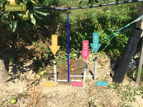
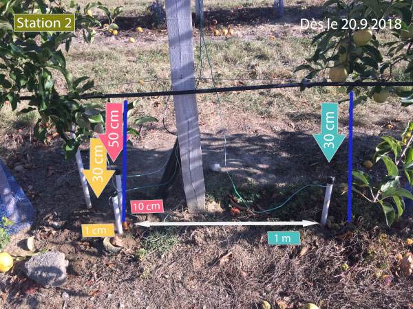
      Station 1 and 2 are two station on fields.
      Station 3 is a node I have at home. I put a little of water on matrix of the watermark until the SWP go to 8kpa and left it dried 1,5 day until the the SWP is 200kps. one hour ago, I put the watermark sensor into water for one hour, and I am going to leave it drying under the sun and compare the graph. Today afternoon (15.9.2018), I am going to update the code of station 1 and 2 to get the SWP value with the equation of Shock

      The red line is the WRM in Ohm and not ml/h (I have not change the unit).
      The yellow line is the SWP return with the equation of Shock

      swp = (int16_t)(3.213 * (wrm/1000) + 4.093) / (1 - 0.009733 * (wrm/1000) - 0.01205 * Tsoil);
      

      and the violet line is the SWP return by

      void kPaCalc(int32_t ResistanceInput, int16_t FTemperatureInput, int16_t &swp){
        // Convert from Resistance to SWP kPa measurement
        // From SMX.pdf datasheet, page 7
        //   550 Ohms =  0 SWP kPa
        //  6000 Ohms = 35 SWP kPa
        // 28075 Ohms =200 SWP kPa
        // using lookup table held in the array  SWPkPAarray   
        // table valid for temperature of 75F, 24C
        // for increase of 1Β°F increase resistance by 1%.
        // ** this function accepts temperature in Fahrenheit units **
        //float newVal;
      
      
        // Adjust compensate resistance for temperature and cpnvert celculs to Fahrenheit
        // per page 8 of SMX.pdf 
        swp=0;
        float ResistanceCompensated =  ResistanceInput *(1 + 0.001*((FTemperatureInput * 1.8 + 32)-75));
        Si.sprint(F("WRMc: "),2); Si.sprintln((int16_t)ResistanceCompensated,2);
        
          if (ResistanceCompensated <= SWPkPAarray[0]) {     // Minimum value
          swp = SWPkPAarray[0+1];
        }
        if (ResistanceCompensated >= SWPkPAarray[16]) {     // Maximum value
          swp = SWPkPAarray[16+1];
        }  
        //for (int i=0; i<SWPkPAarray.length-2; i=i+2) {
        for (int i=0; i<16; i=i+2) {
          if ((ResistanceCompensated >= SWPkPAarray[i]) && (ResistanceCompensated <= SWPkPAarray[i+2])) {
            swp = SWPkPAarray[i+1] - ((SWPkPAarray[i+1]-SWPkPAarray[i+3]) * ((ResistanceInput-SWPkPAarray[i]) / (SWPkPAarray[i+2]-SWPkPAarray[i])));
            break;
          }
        }
        //return newVal;
      }
      

      It's interresting to see that the kPaCalc() progress as a step and stop at 100kpa and jump at 200kpa only when the wrm is 27950.

      I used

      constrain (wrm,550,27950)
      

      so the wrm will not be display higher than 27950 even if it can go over 27950 as say the doc.

      The equation of Shock look perfect and I controlled it with Watermark data reader. The result is similar with a tolerance of 5-10kpa.
      From graph (See Station 3), I also compare the WRM and the SWP from the doc (see page 7) and SWP value matches.

      I wonder why, in the array

      long SWPkPAarray[18]{
      // Watermark Sensor SMX interface Resistance to SWP kPa lookup table per SMX.pdf page 7. 
      // this table is valid at temperature of 75F, 24C  
       550,  0,
      1000,  9,
      1100,  10,
      2000,  15,
      6000,  35,
      9200,  55,
      12200, 75,
      15575, 100,
      28075, 200,
      

      you do not consider a SWP between 100kpa and 200kpa.
      I thing it's very interresting to have value from 100kpa and 200kpa, as 100kpa is the moment when soil need to be irrigate and more we come close to 200kpa, more is dangerous.

      In any case, your function kPaCalc2() from the code you provided to me, 3 mounth ago seems to be best.

      Thank for all
      Cheers

      posted in Development
      pierrot10
      pierrot10
    • RE: How to calibrate a gauge sensor

      @pierrot10
      I make easier. If one liter make 358 tips. One bucket has a value of 2.7932

      rain fall [mm/h] = 2.7932 * nb of tips
      
      posted in General Discussion
      pierrot10
      pierrot10
    • RE: How to calibrate a gauge sensor

      @mfalkvidd said in How to calibrate a gauge sensor:

      You are pouring everything into the funnel, right?

      Hello, yes that right, I poured the litre from my bottle into the funnel.

      If you take a regular drinking glass and pour 1 litre into it, will the height of the water in the glass be 1mm?

      Yes, of course, that make sense!

      I forgetten, but my 3 gauge are in the filed and I can neasure the area surface, unfortunately, but let's say, it 0.05m*0.11m = 0.0055m2 or 55000mm2. I do have the same as below
      alt text

      So in my case, each tips will be egal to
      0.2794mm of high over 0.0055m2 of surface

      If I know I need 358 tips for 1 liter of water (is egal of 1mm over 1m2) within 1 hour. How can I make sure that 0.2794mm is the correct value of my bucket?

      0.2794*358=100.02mm/h
      

      But 100.02mm/h is over 0.0055m2 of surface.

      But how can I calculate the high if I poured the same amount of water in 1m2
      It should be 1mm because we know that 1 liter over 1m2 has a hight of 1mm

      But how calculate it in order to make sure that 0.2794 is the correct value of the bucket?

      posted in General Discussion
      pierrot10
      pierrot10
    • RE: How to calibrate a gauge sensor

      @pierrot10 Other stupid question, does 1liter of water from a bottle, will cover 1m2 of surface with a high of 1mm?

      I red, 1mm/h is egal to 1liter over 1m2 with a high of 1mm

      For sure, I missundertand something πŸ˜–

      posted in General Discussion
      pierrot10
      pierrot10
    • RE: How to calibrate a gauge sensor

      @mfalkvidd Ok, but if the diameter of the hole of the funnel does not change, dot it really make a difflrence?

      What is unclear for me,

      • I which to display the result in mm/h.
      • If I full up 1 liter of water into a bottle, I got about 353 toggles.
      • If divide 1000ml by 353 I get 2.832mm

      Let's say, I wrongly counted the tips of the buncket (I may missed 2or 4 tips over 353) and there were 358 tips then

      1000/358=2.793 => 2.794
      

      Are you agree with my reasoning?

      Should I conclude that bucket is 2.794 and not 0.2794?

      BUT, I oft read this

      The rain gauge is a self-emptying 
      tipping bucket type.  Each 0.011” 
      (0.2794 mm) of rain causes one mo
      mentary contact closure that can 
      be recorded with a digital counter or
       microcontroller interrupt input
      

      I am a bit frustrated because I oft read the number of 0.2794 and I have the same gauge meter as the above picture.

      Then if within one hour, my bucket tips 358 time because I poured 1 liter of water, the calcul is

      358*0.2794mm=100.02mm/h
      

      BUT, 1mm/h is egal to 1liter of water (for 1m2)

      So I guess my problem is a mathematical issue πŸ˜… , or conversion. Isn't? I missed something 😨

      If I make an error of conversion and specially, if I forget to take in consideration the area of the funnel surface.

      I am bit confuse πŸ™‚

      I am not at home yet, and I can not calculate the surface of my funnel yet but I will do as soon as possible (it should be around 50mm*110mm=5500mm2)

      posted in General Discussion
      pierrot10
      pierrot10
    • RE: How to calibrate a gauge sensor

      @mfalkvidd
      Thank for your reply, but something is interreting to me. If the funnel area is twice bigger and the bucket is the same, what will it change? the bucket will toggle when it will get 0.2794mm of water, specially if the hole the funnel has the same diameter. Am I wrong?
      If the diamter is bigger, the buncket will toggle faster.

      posted in General Discussion
      pierrot10
      pierrot10
    • RE: How to calibrate a gauge sensor

      @mfalkvidd
      Hello, thank for your reply. Si let make sure I do not confuse people with my bad english

      For my the bucket is the "tings" which toogle at the right side of the picture:
      alt text

      Should I consider the area of the "funnel" at left side of the picture?

      You wrote:
      My guess is that the area of the bucket is 0.01m2
      if the area of the bucket is well the "things" that toogle, this evening, I will check the width and the length of my bucket and make sure is make 10mm2, but I have a doubt

      alt text

      the width (yellow) make at less 10mm and the length should be about 60mm

      0.01m*0.06m=0.0006m2
      

      πŸ™ƒ

      posted in General Discussion
      pierrot10
      pierrot10
    • How to calibrate a gauge sensor

      Hello all!
      I am checking gauge sensor value and it looks like the values are wrong.
      I followed that example:.

      I have the same gauge and the bunket should be 0.2794mm of water and my mico controller count the number if tips within one hour. Si I supposed, if the bunket tips one, we can say there were 0.2794mm/h of rain.

      I also red that 1mm/h is egal of 1 liter for 1m2 of surface.

      Yesterday, I took a bottle and I filled it up of 1 liter of water and I empty the bottle on my gauge, and I counted the number of tips: 353 tips. (I may have missed 2 or 4 tips).

      So now if I make the calcul

      353x * 0.2794mm = 98.62mm/h
      

      (if i poured 1 liter of water, I should get 0.9862 as 1mm/h is egal of 1 liter).

      If I want to know the size of my bunket, I can calculate, for 1 liter of water I poured (let's take the same number as before 0.9862 istead of 1)

      0.9862mm/h / 353 = 0.002794
      

      Si I can observed that the tutorial may be wrong and the size of the bunket should be 0.002794 instead of 0.2794, BUT I oft obeserved the value of 0.2794

      Or I missunderstanded something, could you enlighten me?

      Secondely, my micro controller count the tips and the the amount of tips within one hour and simply make the calcul:

      [amount of tips]*0.2794=rainfall
      

      the returned value is 13.08
      (in my code I make a small mistake, I inversed 7 and 9 : 0.2974 but it does not make a big difference, I corrected it)

      353*0.2974=104.98
      

      and not 13.08

      but it's interesting to see, if I moved the coma we have 103.8. I wunder I make a mistake of decimal and unit.

      (I also will later double check my gauge in order to make sure that it count correctly)

      Could you unlighten me about to understand and calibrate my gauge?

      Many thank
      Cheers

      posted in General Discussion
      pierrot10
      pierrot10
    • RE: How to read frequency and SWP output from watermark sensor

      I wonder if the problem does not come from here:

      if (ResistanceCompensated >= SWPkPAarray[74]) {}
      

      Should it be not 16?

      posted in Development
      pierrot10
      pierrot10
    • RE: How to read frequency and SWP output from watermark sensor

      Dear hard-shovel,

      I do not know if you are still around and if you can help me a bit.
      I actually put into the soil a watermark at 20cm. I add some water to see the watermark measurement and I used your proposition (code)

      I can not understand why I have a WRm of 518 and it retrun me a 200kPa It should be 0

      Getting WM1 (SMX):
      Frequency at 15: 6896Hz WRM: 518
      WRM: 518
      WRMc: 518
      SWP: 200
      

      Here si the code:
      Note: sw.something. The sw is beacuse I use Seesaw Seesaw borad from Adafruit to have more DIO

      // getting the swp.
      // wm1_power_pin is pin which ppower smx
      // wm1_power_pin is the pin read the value
      // val is the return value
      get_wmsmx(wm1_power_pin, wm1_read_pin, 1000000, val, true);
      mesMesures[c_wm1][capteur_wm1_id].valeur = val; // The final SWP is store here
      

      Dont pain attention at 'alternative'. It's alway true and I will clean the code.

      void get_wmsmx(int powerPin, int pinRead, unsigned long timeout, int16_t &val, bool alternative)
       {
          sw.digitalWrite(powerPin, HIGH);
          delay(1000); // Need to have the sensor "in equilibre" with the soil.
          
          int highInput, lowInput;             // Store high and low time of wave in microseconds
          float totalInput;                     // Temp store of total time of duration for one cycle of high and low pulse
          float frequency;                      // calculated freqency   1/total time of one cycle.
          int16_t swp;
          int percent=0;
          int32_t wrm;
          //float Tsoil=24; //temp
          highInput = pulseIn(pinRead,HIGH);
          lowInput  = pulseIn(pinRead,LOW);
          totalInput = highInput + lowInput;
          
          frequency = 1000000 / totalInput;
         
          if (highInput >0 && lowInput>0)
          {
            Si.sprint(F("Frequency at "),2); Si.sprint(pinRead,2); Si.sprint(F(": "),2); Si.sprint((int16_t)frequency,2); Si.sprint(F("Hz "),2);
          }
          else
          {
            Si.sprint(F("frequency: "),2);
            Si.sprintln(F("Error"),2);
          }
          delay(500);
          
          sw.digitalWrite(powerPin, LOW);
      
          int16_t Tsoil = mesMesures[c_temperature_soil][capteur_temperature_soil_id].valeur;
           
          if(alternative == false)
          {
      // That is my old code. I will remove it
            wrm = map(frequency,48,13233,27950,550); // Must control the frequency for 440 and 27950
            
            Si.sprint(F("WRM: "),2); Si.sprint(wrm,2); Si.sprintln(F(" Ohm"),2);
            Si.sprintln(F("Calculate SWP"),2);
            //kPa = (3.213 * kohms + 4.093) / (1 - 0.009733 * kohms - 0.01205 * Celsius)
            swp = (int16_t)(3.213 * (wrm/1000) + 4.093) / (1 - 0.009733 * (wrm/1000) - 0.01205 * Tsoil);
            Si.sprint(F("SWP: "),2); Si.sprint(swp,2); Si.sprint(F("kPa"),2);
            Si.sprint(F(" for a soil temp of "),2); Si.sprintln(Tsoil,2);
          
            //val = (int16_t)percent;
            val = swp;
          }
          else
          {
              resistanceCalc(frequency, wrm);
              Si.sprint(F("WRM: "),2);
              Si.sprintln(wrm,2);
              kPaCalc(wrm, Tsoil, swp);
              val = swp;
          }
          Si.sprint(F("SWP: "),2); Si.sprintln(swp,2);
       }
      
      //---------------------------------------------------------------
      void resistanceCalc(float frequencyInput, int32_t &wrm){
        wrm=0;
        // Convert from freqency to Resistance measurement
        // From SMX.pdf datasheet, page 6
        // 48 Hz    = 10,000,000 Ohms
        // 76 Hz    =    262,144 Ohms
        // 13233 Hz =          0 ohms 
        // using lookup table held in the array  RESISTORarray   
      
        //frequencyInput = constrain(frequencyInput,50, 13233);
        //float newVal;
        if (frequencyInput <= RESISTORarray[0]) {     // Minimum value
          wrm = RESISTORarray[0+1];
        }
        if (frequencyInput >= RESISTORarray[74]) {     // Maximum value
          wrm = RESISTORarray[74+1];
        }  
        for (int i=0; i<74; i=i+2) {
          if ((frequencyInput >= RESISTORarray[i]) && (frequencyInput <= RESISTORarray[i+2]))
          {
            wrm = RESISTORarray[i+1] - ((RESISTORarray[i+1]-RESISTORarray[i+3]) * ((frequencyInput-RESISTORarray[i]) / (RESISTORarray[i+2]-RESISTORarray[i])));
            break;
          }
        }
        Si.sprint(F("WRM: "),2); Si.sprintln(wrm,2);
      }
      
      void kPaCalc(int32_t ResistanceInput, int16_t FTemperatureInput, int16_t &swp){
        // Convert from Resistance to SWP kPa measurement
        // From SMX.pdf datasheet, page 7
        //   550 Ohms =  0 SWP kPa
        //  6000 Ohms = 35 SWP kPa
        // 28075 Ohms =200 SWP kPa
        // using lookup table held in the array  SWPkPAarray   
        // table valid for temperature of 75F, 24C
        // for increase of 1Β°F increase resistance by 1%.
        // ** this function accepts temperature in Fahrenheit units **
        //float newVal;
      
      
        // Adjust compensate resistance for temperature and cpnvert celculs to Fahrenheit
        // per page 8 of SMX.pdf 
        swp=0;
        float ResistanceCompensated =  ResistanceInput *(1 + 0.001*((FTemperatureInput * 1.8 + 32)-75));
        Si.sprint(F("WRMc: "),2); Si.sprintln((int16_t)ResistanceCompensated,2);
        
          if (ResistanceCompensated <= SWPkPAarray[0]) {     // Minimum value
          swp = SWPkPAarray[0+1];
        }
        if (ResistanceCompensated >= SWPkPAarray[74]) {     // Maximum value
          swp = SWPkPAarray[16+1];
        }  
        //for (int i=0; i<SWPkPAarray.length-2; i=i+2) {
        for (int i=0; i<16; i=i+2) {
          if ((ResistanceCompensated >= SWPkPAarray[i]) && (ResistanceCompensated <= SWPkPAarray[i+2])) {
            swp = SWPkPAarray[i+1] - ((SWPkPAarray[i+1]-SWPkPAarray[i+3]) * ((ResistanceInput-SWPkPAarray[i]) / (SWPkPAarray[i+2]-SWPkPAarray[i])));
            break;
          }
        }
        //return newVal;
      }
      
      long RESISTORarray[76] = {
      // Watermark Sensor SMX interface Hz to Resistance lookup table per SMX.pdf page 6. 
      48,  10000000,
      76,  262144,
      85,  196608,
      103, 131072,
      122, 98304,
      157, 65536,
      194, 49152,
      264, 32768,
      335, 24567,
      476, 16384,
      612, 12288,
      874, 8192,
      1135,  6144,
      1623,  4096,
      2071,  3072,
      2862,  2048,
      3557,  1536,
      4697,  1024,
      5596,  768,
      6932,  512,
      7878,  384,
      9104,  256,
      9882,  192,
      10802, 128,
      11312, 96,
      11893, 64,
      12200, 48,
      12526, 32,
      12708, 24,
      12871, 16,
      12962, 12,
      13047, 8,
      13092, 6,
      13139, 4,
      13162, 3,
      13186, 2,
      13209, 1,
      13233, 0,
      };
      
      long SWPkPAarray[18]{
      // Watermark Sensor SMX interface Resistance to SWP kPa lookup table per SMX.pdf page 7. 
      // this table is valid at temperature of 75F, 24C  
       550,  0,
      1000,  9,
      1100,  10,
      2000,  15,
      6000,  35,
      9200,  55,
      12200, 75,
      15575, 100,
      28075, 200,
      };
      

      Many thank!!

      posted in Development
      pierrot10
      pierrot10
    • RE: How to read frequency and SWP output from watermark sensor

      @hard-shovel
      I think, now it's clearer for me.

      First, SMX module has a range from 48hz to 13233hz
      But the watermak sensor has a range from 550 to 27950 ohm

      As we use watermark to measure the soil mostire, wehave to consier the range of 550 to 27950 which match with 6700Hz (more or less) and 310Hz. What is below or above is not relevant for moisture measurement with Wathermark.

      Are you agree with me?

      posted in Development
      pierrot10
      pierrot10
    • RE: How to read frequency and SWP output from watermark sensor

      @hard-shovel
      Hello,it's verry interresting what you shared.
      Today I left the SMX input open. No sensor no resistance. I discovered, I get the same value when the sensor is in a fully dried soil. And I did not have the sensor with me.

      Yes, I have a box that I fill up with soil of the crop where the sensors will be for the measurement.
      We only want to monitor the soil moiture from June to Septembre and the result will be display in a graph.

      Some week ago, I wrote a loop to simulate the watermark voltage. In your second table you show that KPA can be from -332 to -1300 and then immediately to a positif number. That difference make me souspicious. I am still souspicous when I look from 48Hz to 157Hz (the doc give a range of frequency from 48Hz to 13233Hz.)

      But at the final, as I understood, what is relevant is from 1220Hz to +/- 310hz (from 550Ohm to 27950). From 27950 and above, the soil is fully dry, whatever if the kPa goes to -1300 or -352. And from 550Ohm or below, the soil is fully wet.

      posted in Development
      pierrot10
      pierrot10
    • RE: How to read frequency and SWP output from watermark sensor

      @hard-shovel
      Thank a lot for your code, I tested it.

      It's interresting but I finaly got the same values as I tested until now with untrustable function (wmsmx() )

      I compared the return value of

      //---------------------------------------------------------------
      long kPaCalc(float ResistanceInput, float FTemperatureInput){
       // Convert from Resistance to SWP kPa measurement
       // From SMX.pdf datasheet, page 7
       //   550 Ohms =  0 SWP kPa
       //  6000 Ohms = 35 SWP kPa
       // 28075 Ohms =200 SWP kPa
       // using lookup table held in the array  SWPkPAarray   
       // table valid for temperature of 75F, 24C
       // for increase of 1Β°F increase resistance by 1%.
       // ** this function accepts temperature in Fahrenheit units **
       Serial.print(F("DEBUG: ResistanceInput: ")); Serial.println(ResistanceInput);
       float newVal;
      
       // Adjust compensate resistance for temperature.
       // per page 8 of SMX.pdf 
       float ResistanceCompensated =  ResistanceInput *(1 + 0.001*(FTemperatureInput-75));;
       Serial.print(F("DEBUG: ResistanceCompensated: ")); Serial.println(ResistanceInput);
       
         if (ResistanceCompensated <= SWPkPAarray[0]) {     // Minimum value
         newVal = SWPkPAarray[0+1];
       }
       if (ResistanceCompensated >= SWPkPAarray[74]) {     // Maximum value
         newVal = SWPkPAarray[16+1];
       }  
       //for (int i=0; i<SWPkPAarray.length-2; i=i+2) {
       for (int i=0; i<16; i=i+2) {
         if ((ResistanceCompensated >= SWPkPAarray[i]) && (ResistanceCompensated <= SWPkPAarray[i+2])) {
           newVal = SWPkPAarray[i+1] - ((SWPkPAarray[i+1]-SWPkPAarray[i+3]) * ((ResistanceInput-SWPkPAarray[i]) / (SWPkPAarray[i+2]-SWPkPAarray[i])));
           break;
         }
       }
       return newVal;
      }
      

      with my function I did not trust

      void get_wmsmx(int powerPin, int pinRead, unsigned long timeout, int16_t &val)
       {
      
          /*
          * Second soluion more precise
          */
          int highInput, lowInput;             // Store high and low time of wave in microseconds
          float totalInput;                     // Temp store of total time of duration for one cycle of high and low pulse
          float frequency;                      // calculated freqency   1/total time of one cycle.
          float swp;
          int wrm;
          //float Tsoil=24; //temp
          highInput = pulseIn(pinRead,HIGH);
          lowInput  = pulseIn(pinRead,LOW);
          totalInput = highInput + lowInput;
          
          frequency = 1000000 / totalInput;
          percent = map(frequency,48,13233,0,100);
         
          
          if (highInput >0 && lowInput>0)
          {
            Si.sprint(F("Frequency2 at "),2); Si.sprint(pinRead,2); Si.sprint(F(": "),2); Si.sprint(frequency,2); Si.sprint(F("Hz "),2);
            Si.sprint(F("("),2); Si.sprint(percent,2); Si.sprintln(F("%)"),2);
          }
          else
          {
            Si.sprint(F("frequency: "),2);
            Si.sprintln(F("Error"),2);
          }
          delay(500);
          
          sw.digitalWrite(powerPin, LOW);
      
      /*
      *  Calculate  SWP (kPa)
      */
          uint8_t Tsoil = mesMesures[c_temperature_soil][capteur_temperature_soil_id].valeur;
          wrm = map(frequency,48,13233,27950,550);
      
          Si.sprint(F("WRM: "),2); Si.sprint(wrm,2); Si.sprintln(F(" Ohm"),2);
          Si.sprintln(F("Calculate SWP"),2);
          //kPa = (3.213 * kohms + 4.093) / (1 - 0.009733 * kohms - 0.01205 * Celsius)
          swp = (3.213 * (wrm/1000) + 4.093) / (1 - 0.009733 * (wrm/1000) - 0.01205 * Tsoil);
          Si.sprint(F("SWP: "),2); Si.sprint(swp,2); Si.sprint(F("kPa"),2);
          Si.sprint(F(" for a soil temp of "),2); Si.sprintln(Tsoil,2);
          
          val = (int16_t)percent;
       }
      

      the return value with mine function

      SWP: 202.77kPa for a soil temp of 24C
      It's very close to yours

      I also was very interrested about the return value of yours second function:

      long kPaCalc2(float ResistanceInput, float CTemperatureInput){
        // Second Method of conversion
        // Convert from Resistance to SWP kPa measurement
        // From SMX.pdf datasheet, page 9
        // kPa = (3.213 * kohms + 4.093) / {1 - 0.009733 * kohms - 0.01205 * Celsius)
        // ** this function accepts temperature in Celsius units **
        
        ResistanceInput = ResistanceInput/1000;     // ohms to Kohms
        float newVal = (3.213 * ResistanceInput + 4.093) / (1 - 0.009733 * ResistanceInput - 0.01205 * CTemperatureInput);
        return newVal;
      }
      

      because it displays -332.00kpa, and this was the result I always got before adding

      wrm = map(frequency,48,13233,27950,550);
      

      in my fonction wmsmx();

      I always thout that -332 was a error as I was convinced that it could not exceed -200 and SWP is always negatif from 0 to -200.

      I am still wondering why we got a value of -332 instead of -200 (or around -200)

      So what is more relevent between kPaCalc and kPaCalc2?
      This study also use the same formula as you, but they spoke about 0 -239kPa

      According to the manufacturer’s sensor specifications, the rated range of measurement of the Watermark 200SS sensors is from 0 to βˆ’239 kPa, although the normal usable range is from 0 to βˆ’200 kPa, where a reading around 0 kPa would indicate that the soil is at or near saturation and a reading at or near βˆ’200 would indicate a very dry soil with little or no plant available water. There are several types of commercial loggers that can automatically read the Watermark 200SS sensors at specified time intervals and store the collected data, and a device to manually read these sensors is also available (Figure 1(b)).
      

      Do you think they provide the formula but they do not say all about how the get -239? (otherwise they will have -324Kpa (or somethink about this...)

      I conclude, the best way is to use your proposition kPaCalc() because you consider the manufacturer TABLE1 value (page6) but your value is positif.

      Do you have idea about positif vs negatif kPa value (200 or -200)?
      I also conclude that my result was not sur wrong, while I expected it as obsolete :).

      What do you tink about how I calculate kPa in my function wmsmx(), as I am using the map function to get the Rwm (watermark sensor)

      Should I better follow your example as your "hard coded" the table value?

      long RESISTORarray[76]
      long SWPkPAarray[18]
      long resistanceCalc(float frequencyInput)
      

      Now my main worries is about negatif SWP value vs positif SWP value.

      Many thank!!!!
      Cheers

      posted in Development
      pierrot10
      pierrot10
    • RE: How to read frequency and SWP output from watermark sensor

      @hard-shovel
      It's a huge, great what you wrote!!!
      I will test it tomorrow!!! and compare the two different to calculate kpa ( kPaCalc2() and kPaCalc() )
      πŸ‘

      posted in Development
      pierrot10
      pierrot10
    • RE: How to read frequency and SWP output from watermark sensor

      @hard-shovel
      Ouha, your are a genius!!
      I am going to look at this deeply. I keep you up to date!
      Thaaank!!!!!!!

      posted in Development
      pierrot10
      pierrot10
    • RE: How to read frequency and SWP output from watermark sensor

      @hard-shovel said in How to read frequency output from watermark sensor:

      That does not seem to make sense to me, as when i chart the numbers, it seems to me the most useful range according to the KPa numbers will not be very sensitive with your figures ranging from an intger of 9 down to 0.

      I am sorry but I was busy with another problem that now I fixed.

      First of all. The Analog (A1) has a pull-up resistance.
      Secondely, you asked me why I do not use the kPa unit instead of percent.

      The reason is I do not know how. In fact I know but I can not get a correct value. I followed your recommandation and I use pulseIN HIGH and LOW

      HighInput = pulseIn(input_pin,HIGH);
      LowInput  = pulseIn(input_pin,LOW);
      

      I tested it while the sensor is in dry, dry soil and it return me 48Hz. I have not add water into the soil, as I need to keep it dry for now. But I believe my code work fine to get Hz

      /*
          * Second soluion more precise
          */
          int highInput, lowInput;             // Store high and low time of wave in microseconds
          float totalInput;                     // Temp store of total time of duration for one cycle of high and low pulse
          float frequency;                      // calculated freqency   1/total time of one cycle.
          float swp, wrm;
          float Tsoil=24; //temp
          highInput = pulseIn(pinRead,HIGH);
          lowInput  = pulseIn(pinRead,LOW);
          totalInput = highInput + lowInput;
          
          frequency = 1000000 / totalInput;
          percent = map(frequency,48,13233,0,100);
         
          
          if (highInput >0 && lowInput>0)
          {
            Si.sprint(F("Frequency2 at "),2); Si.sprint(pinRead,2); Si.sprint(F(": "),2); Si.sprint(frequency,2); Si.sprint(F("Hz "),2);
            Si.sprint(F("("),2); Si.sprint(percent,2); Si.sprintln(F("%)"),2);
          }
          else
          {
            Si.sprint(F("frequency: "),2);
            Si.sprintln(F("Error"),2);
          }
          delay(500);
      

      Great, thank a lot!!!!!!!!!!

      But I would like to get the value in kPa and when micro-controller is not connected to WM, my formul return me -332.58kPa while it should be -199kpa for fully dried and 0kpa for fully wet.I got the same result when I connect my micro-controller to my watermark sensor in a realy realy dry soil. (I have a large box with crop soil that I leave it drying)
      The doc says:

      The resistance ranges from 550 ohms in saturated soil, 0.0 kPa, to
      27950 ohms in bone dry soil, 199 kPa
      

      I wonder if I calculate correctly. The doc give a forumle to get the swp in kpa

      kPa = (3.213 * kohms + 4.093) / {1 - 0.009733 * kohms - 0.01205 * Celsius)
      

      and I need to know the value of 'kohms' which is the resistance of my watermark sensor when dry or wet.

      I guess my mistake is here because, I actually a Watermark resistance of 10000000 ohm.

      If you know the watermark sensor and still has the patience to help, I would like to understand the difference between the Table 1 and table 2 on page 6 and 7

      As I wrote, I have box where I add crop soil and leave it dry until is really really dry. I measure the soil moisture with a watermark, and it return me 48Hz, which sound good as the soil is really really dry. Then the watermark resistance should be 10000000 accoring to table1, but I am confused because on page 9

      The resistance ranges from 550 ohms in saturated soil, 0.0 kPa, to
      27950 ohms in bone dry soil, 199 kPa. That is at 75 degrees Fahrenheit, 24 degrees Celsius
      

      Then how can I get the right watermark resistance value from frequency and then use it with the following formul to get from 0 to -199kpa?

      swp = (3.213 * (wrm/1000) + 4.093) / (1 - 0.009733 * (wrm/1000) - 0.01205 * Tsoil);
      

      this return me -332.58kPa

      Then How can I calculate wrm (Resistance of watermark)?

      Thank a lot

      posted in Development
      pierrot10
      pierrot10
    • RE: How to read frequency and SWP output from watermark sensor

      Dear Hard-shovel.

      Realy a great thank for your reply.It's too late now to answer of all of your obersvation (it's 1.30 am at my place), but I will take care of this tomrrow.

      Just to answer for this

      What is the purpose of the J6 connector, as i should think that connecting any cable or meter will effect the capacitance and change the output frequency.
      

      I build the circuit myself and I was not sure about the Film capacitor C15_1. I juts add J6 in case I make a mistake about C15_1. In that case, I can add a different capacitor on J6. But it should remind open and remove it later unless C15_1 (SMD) does not match. I have a doubt about C15_1, but not about the no-SMD capacitor that I can place on J6 holes. πŸ˜‰

      About Q3, yes of course
      About Q2. Yes I thought to connect to PA15 instead of 3.3V. I though there is no impact if I keep RESET permanentely to 3.3, but I can have it to PA15, when the DIO of my processor is HIGH to power the SMX circuit.
      About Q1: I didnot foresee a pull up resistor on A1 and Ido not know if my microcontroller has one (Adafruit Feather MO adalogger), but I will check it tomorrow.

      I will better read your additonnal helpfully next comments

      Great, thank a lot for your suggestion and comments
      Cheers
      Thank

      posted in Development
      pierrot10
      pierrot10
    • RE: How to read frequency and SWP output from watermark sensor

      Dear Hard-shovel

      Thank a lot for your explication. That help!

      I use freqency measures because the voltage output need to have an input pf 4.5V. My circuit worj with 3.3V even ifI believe it would work.

      I created that schema
      alt text.
      Watermark is connected to W15_2 and _1
      On PA15, I power the watermark with DIO pin of my microcontroller, and then I take the frequency measure on A5 (work as digitalRead). In that way, I controll the power and power the watermark only when I need.

      I have 3 time that circuit as I have 3 watermarks to measure at 3 different level.

      I use that code to get the frequeny

      /*
       * GET Watermarksvalue
       */
      unsigned long measureSMX(int powerPin, int pinRead, unsigned long timeout){
        #ifdef ST2
          unsigned long duration;
         float percent=0.0;
          sw.digitalWrite(powerPin, HIGH); // (sw = Seesaw board from Adafruit)
          delay(1000);
          //duration = pulseIn(pinRead, HIGH, timeout);
          /*
          while(1)
          {
            //Serial.println( digitalRead(pinRead));
            //delay(1);
          }
          */
        
          duration = pulseIn(pinRead, HIGH);
          sw.digitalWrite(powerPin, LOW);
      
        
          //percent= map(duration,50,10000,0,100);
          percent = duration*100/11000;
          #ifdef DEBUG
            Si.sprint(F("Frequency at "),2); Si.sprint(pinRead,2); Si.sprint(F(": "),2); Si.sprint(duration,2); Si.sprint(F("Hz "),2);
            Si.sprint(F("("),2); Si.sprint(percent,2); Si.sprintln(F("%)"),2);
          #endif
          delay(2000);
          return (int)percent;
        #endif
      }
      

      and the measures look good. But my code is very simple in comparaison of your and I would happy to imporve it (and correct/remove error)

      Your exemple look very interrestin but why do your need to mesure once with LOW and once with HIGH

      HighInput = pulseIn(input_pin,HIGH);
        LowInput  = pulseIn(input_pin,LOW);
      

      I suppose I should do as you demonstrated.

      You also mentionned that the microcontroller should be 16Mhz. I supposed it's the minimum requiered?
      My microcontroller is a 48Mhz. The micro-controller spped has an important on frequency result/calculation?

      Thank for helping!

      posted in Development
      pierrot10
      pierrot10
    • RE: How to read frequency and SWP output from watermark sensor

      Hello, thnak a lot for your replies.I am going to read it carefully tomorrow. It's look very interresting. Cheers

      posted in Development
      pierrot10
      pierrot10
    • RE: How to read frequency and SWP output from watermark sensor

      Hello
      Ir's not easy has you say.
      The doc say:

      A special circuit is needed to measure the electrical resistance of the Watermark sensor. DC currents
      must not be allowed to flow through the wet part of the circuit, or else irreversible reactions
      will occur and spoil the readings. AC excitation avoids these problems, by reversing the polarity
      of the current many times per second, so that no net reaction takes place at either electrode. The
      circuit must also isolate the sensor electrodes from galvanic currents in the soil environment
      

      We need two analog pin, one to measure in one sens, and the second when we alternated to power. I spend so much time on this without a good result, that I would appreciate to do it with the SMX electrical interface for Watermark.

      I am tryinf to find thw right connection with an Arduino to measure the frequency, with pain. Some of you has an experience with it?

      posted in Development
      pierrot10
      pierrot10
    • How to read frequency and SWP output from watermark sensor

      Hello All,

      I choose to measure soil moisture with a Watermark sendor and an electric interface for Watermark (SMX)
      The SMX give 3 options to read the result: Voltage, courent and frequency.
      Look at the page 3, first schema.

      I created my breadboard but I have not test it yet because I no expertise to develop a code to read the frequency with a digital read.

      Someone can share an expemple or an experience?

      Thank a lot

      posted in Development
      pierrot10
      pierrot10
    • Someone can help to measure with a watermark moisture sensor

      Good day.

      Since a couple of day, I am trying to use a watermark sensor without bug success.
      I got servreal documentation
      First I found good information on
      SMX datasheet
      read paragraph 2 and 3.
      I also look at this article and I worked on the schema b) under the title "Reading the Watermark 200SS Sensors".
      Voltage divider
      Unfortunately, I can not get a reliable value.

      I also found this good schema alt text.

      Finally, I also found this another alaterative

      Which look nice but apparently there is a condensator in a bad sens.

      I spent about four days, trying with Voltage divider.
      I specially follow this tutorial, But I never got a correct value and I do not know if I am doing something else wrong or if I missed a detail.
      I have two new Watermark. One is wet and the second is fully dry. I also have a WATERMRK digital reader and when I measure it with the reader, I got the value 199 for the dry sensor, and 0 for the wet sensor.

      When I take the measure with my Adafruit Trinket Pro by alernating the polartity 10 time, I never get a value similar to the digital reader. The value are close 300 and more.

      Now I am going to try the second schema, but as I sepnd so many time on this issue, I would like to know if some one as a good expertise with WATERMAK and adafruit or arduino board and how you develop you schetch t measure a Soil Water potetial in Kpa?

      If you develop a such sensor with Arduino or adafruit, sharing your experience (Any links, exemple, titorial, recommandation), will help a lot.!

      Many thank
      Cheers

      posted in General Discussion
      pierrot10
      pierrot10
    • RE: Watermark arduino 3.3 headache

      Hello,
      I hope your are still around about this topic.

      I very very oft read that we need to take twice the measure by inversing the polarity. As say the doc

      A special circuit is needed to measure the electrical resistance of the Watermark sensor. DC currents
      must not be allowed to flow through the wet part of the circuit, or else irreversible reactions
      will occur and spoil the readings. AC excitation avoids these problems, by reversing the polarity
      of the current many times per second, so that no net reaction takes place at either electrode
      

      In your above sketch, you do not inverse the polarity and it's look like you read 10 time with the same polarity.

      However, in the above schema, it look like you power (3.3 at the sensor) once the WATERMAK, and then 3.3 at the resistance.

      Could you explian me your sketch code? And what does the capacitor?

      Thank a lot..

      posted in Troubleshooting
      pierrot10
      pierrot10
    • Where to find a rainfall sensor

      Gooday all!!!

      I am actually working one a project which consist of measuring the rainfull.
      I pain to find sensors. I found some but the 2 I found include wind sensor.

      For now, I just would like to get a rain gauge which work with Arduino and Pycom board. I am not looking for the best and more expensive but a midlle range of quality with efficient result.

      Where would you recommand me to get rain gauge? Would you know something in switzerland?

      Many thank

      posted in My Project
      pierrot10
      pierrot10