@NeverDie I have ordered 10 pieces each time.
qqlapraline
@qqlapraline
Posts
-
Which PCB fab do you currently like the best?Qq
-
Which PCB fab do you currently like the best?For the past 2 weeks, I had the opportunity to challenge PCBWAY and JLCPCB at almost the same time for the same boards including turnkey components and PCBA.
Here is the short version of the story:
PCBWAY:- Ordered on October, 12th
- PCB finished on October, 14th - 37 hours later
- Components sourced on October, 18th
- PCBA finished on October, 21st
- Parcel shipped on October, 21st
- Parcel received on October, 25th
- Price: $208.61 including VAT and shipping ($35.73)
JLPCB:
- Ordered on October, 20th
- PCB finished on October, 21th - 20 hours later
- Components sourced on October, 20th (yes)
- PCBA finished on October, 21st - 8 hours after PCB !
- Parcel shipped on October, 22nd
- Parcel received on October, 24th !
- Price: $82.98 including VAT and shipping ($24.19)
At the arrival, all the boards have been tested successfully from both providers.
So, basically, JLCPCB is the winner. Oh by the way, the quality of JLCPCB is a little higher than PCBWAY: black PCB.QQ.
-
Pellet burner MonitoringAfter a 4 years work, here are some samples of my pellet consumption.
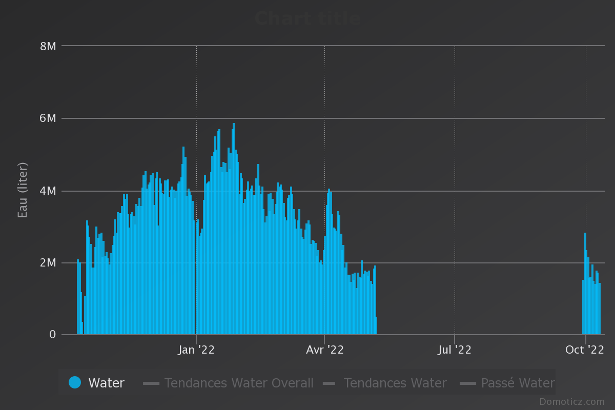

Now, guess when I usually stop the boiler ..:)
Cheers,
QQ.
-
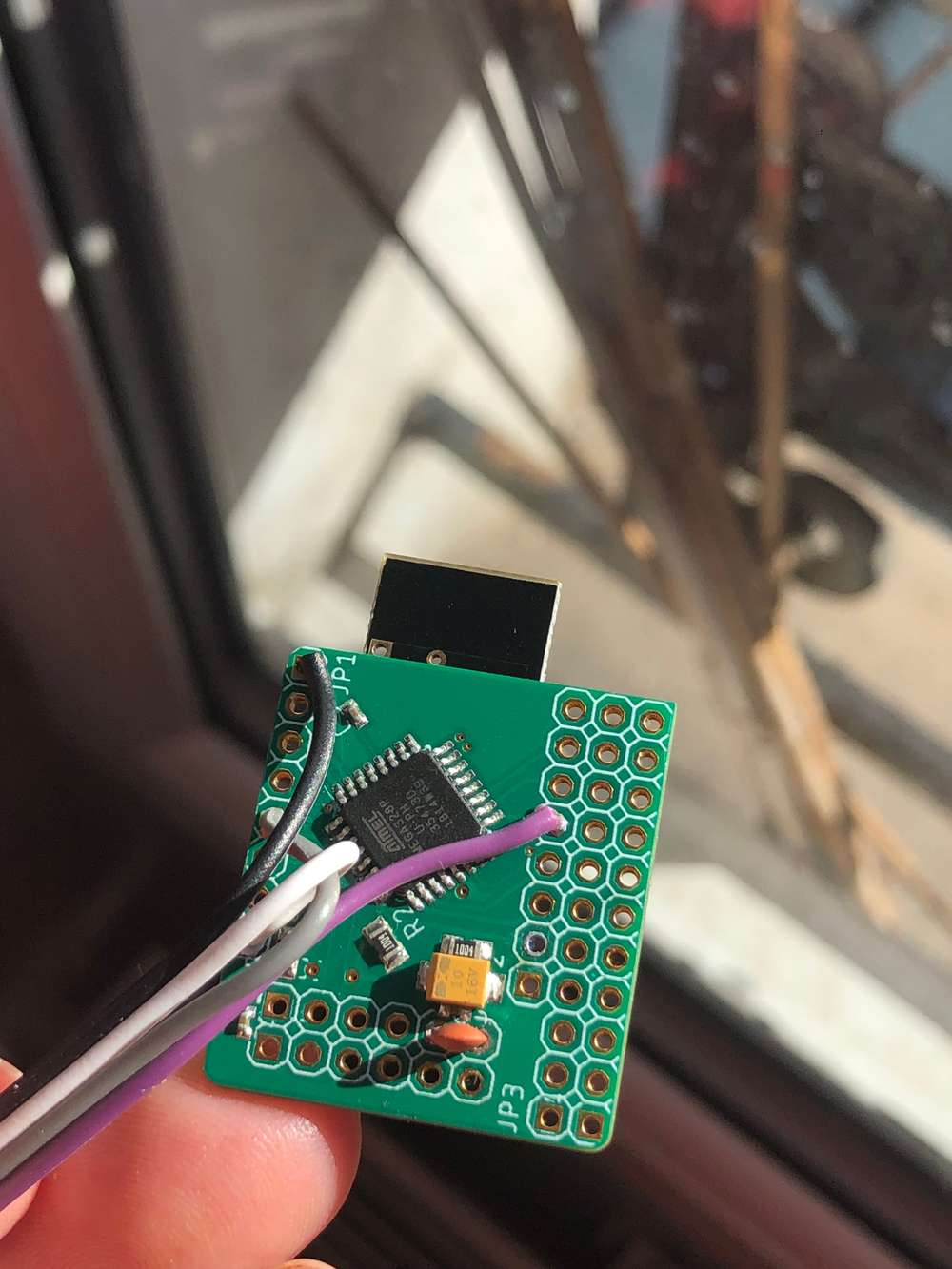
Find Parent (yeah, I know)You are right, @NeverDie. Actually, my power supply is coming from a french power meter, that means a lot of noise - as I'm DC from a 50Khz AC :). So, I did two things. Adding a 330 pF capacitor at the entry point of my board and a 47µF right next to the NRF24.
Finally, I've upgrade my design to add a tantalium capacitor right next to the smd pads.
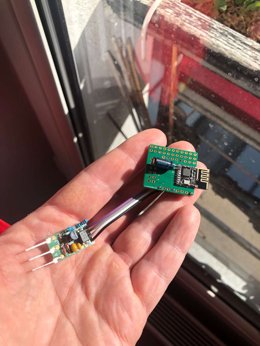
Global view:
Zooming the back with the polarized capacity (old fashion):
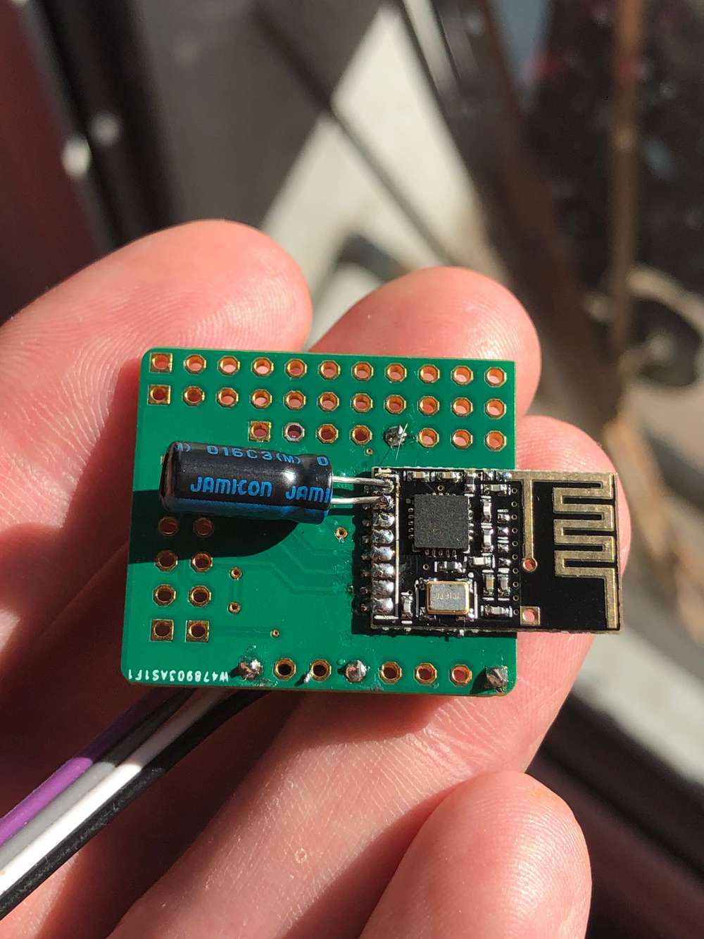
Front view:
New design:
Cheers,
QQ
-
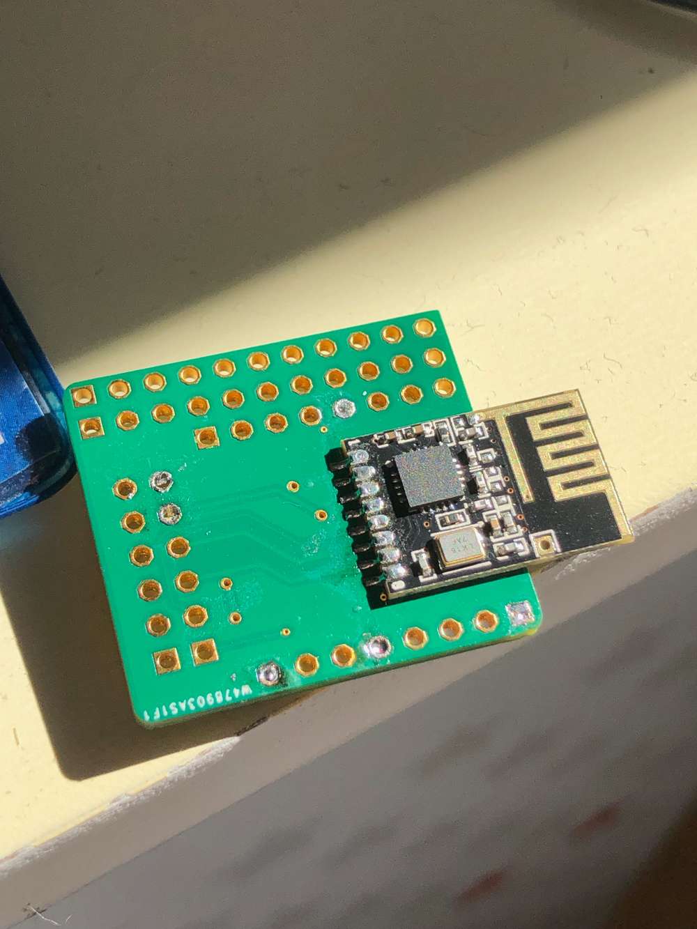
Find Parent (yeah, I know)@mfalkvidd guess what…the capacity strikes again. I’ve soldered a 47uF right on the nrf24l01+ pins and…it works.
Would someone explain me the logic there ? The traces between the pins and the capacity were like 10mm long max.
Oh well.Qq.
-
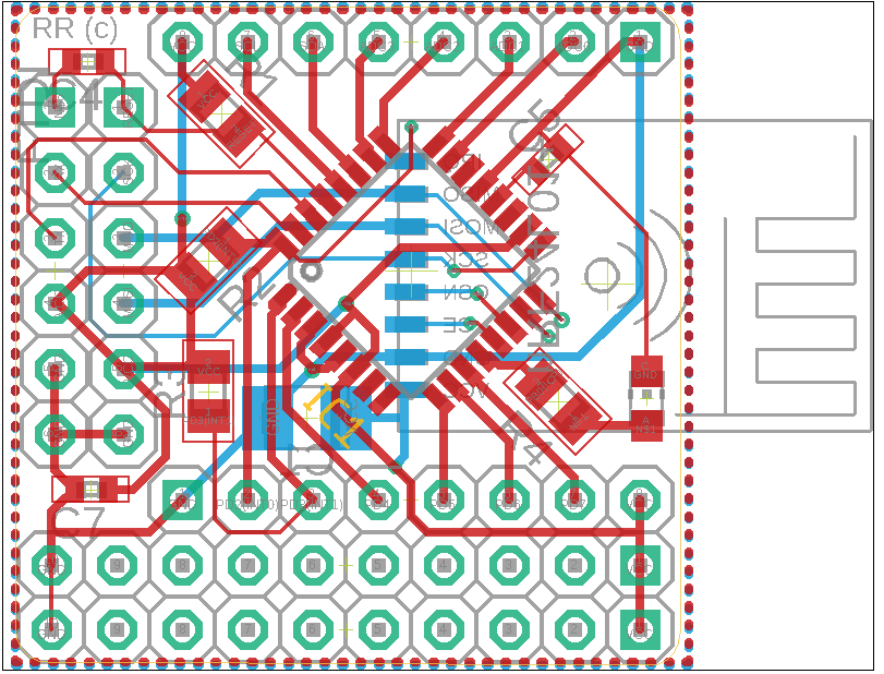
Find Parent (yeah, I know)@qqlapraline here are the pictures of my PCB. Front and Back.

QQ.
-
Find Parent (yeah, I know)@mfalkvidd I think I did.
- Photos of the nodes will arrive this evening
- I have tried various distances as well as various power settings on the node
- the node was tested using serial adapter power (3.3V)
-
Find Parent (yeah, I know)@mfalkvidd absolutely. I have 6 various nodes (temp, power, ..) with period of update from 20 to 90 seconds..
-
Find Parent (yeah, I know)Hello guys,
It's been a while since my last posting.
I have setup a new sensor using my own PCB that is pretty much the same as this one.I have tried many setups and now I'm using a basic node code
// mysensors

#define DEBUG_ENABLED
#define DEBUG_TI

// Enable debug prints to serial monitor
#define MY_DEBUG

#define MY_RADIO_RF24

#define MY_RF24_PA_LEVEL RF24_PA_LOW

#define RELEASE "0.0.1"

#include <MySensors.h>

//#define MY_NODE_ID 36

#define OPEN 1
#define CLOSE 0
#define CHILD_ID 1

MyMessage msg(CHILD_ID, V_TRIPPED);

uint8_t value = OPEN;

void presentation()
{
  Serial.println("Presentation");
  present(CHILD_ID, S_DOOR);
}

void setup() {
  // put your setup code here, to run once:
  Serial.begin(115200);
  Serial.println("End setup");
}

void loop() {
  // put your main code here, to run repeatedly:
  value = value == OPEN ? CLOSE : OPEN;
  Serial.println("Sending message");
  send(msg.set(value));
  Serial.println("Sleeping");
  sleep(10000);
}
But, guess what: my node is not getting any parent response.
Here is the output I get from the serial port on my node:
18096 TSM:FAIL:RE-INIT
18098 TSM:INIT
18104 TSM:INIT:TSP OK
18106 TSM:FPAR
18110 ?TSF:MSG:SEND,255-255-255-255,s=255,c=3,t=7,pt=0,l=0,sg=0,ft=0,st=OK:
20119 !TSM:FPAR:NO REPLY
20121 TSM:FPAR
20123 ?TSF:MSG:SEND,255-255-255-255,s=255,c=3,t=7,pt=0,l=0,sg=0,ft=0,st=OK:
22132 !TSM:FPAR:NO REPLY
22134 TSM:FPAR
22136 ?TSF:MSG:SEND,255-255-255-255,s=255,c=3,t=7,pt=0,l=0,sg=0,ft=0,st=OK:
24147 !TSM:FPAR:NO REPLY
24150 TSM:FPAR
24152 ?TSF:MSG:SEND,255-255-255-255,s=255,c=3,t=7,pt=0,l=0,sg=0,ft=0,st=OK:
26161 !TSM:FPAR:FAIL
26163 TSM:FAIL:CNT=2
26165 TSM:FAIL:DIS
26167 TSF:TDI:TSL
and the one on the gateway:
Oct 03 23:06:37 DEBUG TSF:MSG:READ,255-255-255,s=255,c=3,t=7,pt=0,l=0,sg=0:
Oct 03 23:06:37 DEBUG TSF:MSG:BC
Oct 03 23:06:37 DEBUG TSF:MSG:FPAR REQ,ID=255
Oct 03 23:06:37 DEBUG TSF:PNG:SEND,TO=0
Oct 03 23:06:37 DEBUG TSF:CKU:OK
Oct 03 23:06:37 DEBUG TSF:MSG:GWL OK
Oct 03 23:06:37 DEBUG ?TSF:MSG:SEND,0-0-255-255,s=255,c=3,t=8,pt=1,l=1,sg=0,ft=0,st=OK:0
Oct 03 23:06:38 DEBUG GWT:RFC:C=0,MSG=0;0;3;0;18;PING
Oct 03 23:06:39 DEBUG TSF:MSG:READ,255-255-255,s=255,c=3,t=7,pt=0,l=0,sg=0:
Oct 03 23:06:39 DEBUG TSF:MSG:BC
Oct 03 23:06:39 DEBUG TSF:MSG:FPAR REQ,ID=255
Oct 03 23:06:39 DEBUG TSF:CKU:OK,FCTRL
Oct 03 23:06:39 DEBUG TSF:MSG:GWL OK
Oct 03 23:06:39 DEBUG ?TSF:MSG:SEND,0-0-255-255,s=255,c=3,t=8,pt=1,l=1,sg=0,ft=0,st=OK:0
Oct 03 23:06:41 DEBUG TSF:MSG:READ,255-255-255,s=255,c=3,t=7,pt=0,l=0,sg=0:
Oct 03 23:06:41 DEBUG TSF:MSG:BC
Oct 03 23:06:41 DEBUG TSF:MSG:FPAR REQ,ID=255
Oct 03 23:06:41 DEBUG TSF:CKU:OK,FCTRL
Oct 03 23:06:41 DEBUG TSF:MSG:GWL OK
Oct 03 23:06:42 DEBUG ?TSF:MSG:SEND,0-0-255-255,s=255,c=3,t=8,pt=1,l=1,sg=0,ft=0,st=OK:0
Oct 03 23:06:43 DEBUG TSF:MSG:READ,255-255-255,s=255,c=3,t=7,pt=0,l=0,sg=0:
Oct 03 23:06:43 DEBUG TSF:MSG:BC
Oct 03 23:06:43 DEBUG TSF:MSG:FPAR REQ,ID=255
Oct 03 23:06:43 DEBUG TSF:CKU:OK,FCTRL
Oct 03 23:06:43 DEBUG TSF:MSG:GWL OK
Oct 03 23:06:44 DEBUG ?TSF:MSG:SEND,0-0-255-255,s=255,c=3,t=8,pt=1,l=1,sg=0,ft=0,st=OK:0
Any help would be rewarded by a coffee, beer and may be by a bottle of Chablis if you have the answer :)
QQ.
ps: yes, I have a great 33µF capacity right next to my radio
pps: yes, I have tried a different NRF24L01+ module
ppps: isn't it tiring to have multiple "PS" ? :) -
Arduino Nano Every problemI was wondering the kind of modification needed to support ATMEGA4808/4809.
I have read again the MyConfig.h and MySensors.h, they look quite good.
Though, there might be some updates to be done in the hal/architecture/AVR folder ..:astonished: -
Low power Distance Sensor - Hardware issuesGreat, @peerv !
That's a very good idea.
Do you have reasonable power consumption ? -
Low power Distance Sensor - Hardware issues@chbla, I'm quite puzzled.
As it works on the breadboard, of course, I would chase for bad soldering. For instance, the mosfet gate controled by pin 7.Any picture of the arduino pro mini ?
-
Low power Distance Sensor - Hardware issues@chbla, you are right. As mentionned on the schema, it should be connected to GNDT (the triggered GND). And now I do understand your point.
-
Low power Distance Sensor - Hardware issues@chbla well, yes. As the level adapter AND the booster are triggered only when needed (during the measure time), I don't see where it closes the loop.
By maybe I misunderstand something. Where do you loose some current ? The trigger pin from the HC-SR04 ?QQ.
-
Pellet burner MonitoringYep ! And that's why it's fun ! :)
But my zc detector will work too. My first tests are OK :)QQ.
-
Pellet burner Monitoring@zboblamont : it's not exposed under the tank and totally shrouded on the boiler side
@gohan: right, by I really don't want to touch the wires. And neutral and phase are inside a single cable with not enough space to put a clamp..;)
-
Low power Distance Sensor - Hardware issuesFrom my experience, the transistor (or mosfet) is key to allow enough current to the DC-DC booster. Otherwise, it will not provide the appropriate voltage because max current getting out of a digital pin from Arduino is around 40 mA.
QQ.
-
Pellet burner Monitoring@Nca78, actually, I did not want to touch the existing cables to avoid any claim from the maintenance guy ;) And as I could not access one single wire, I had to find another way. Interesting enough, using the existing connecting screws was easier.
@zboblamont: the picture is quite not clear but the motor is very well protected to avoid any mechanical injury. And, probably as a consequence, there is not detectable magnetic field coming out of it.
@bjacobse: I have considered this as well (as well as some kind of a gauge based on pressure or anything else in the tank). But, unfortunatly, as this is a 7 tons / 11 m3 pellet tank, it is filled by a truck blowing pellets into it....making the life of the ultrasonic sensor really not long :)
Furthermore, ultrasonic sensor would be good to measure a level with a very large error margin. With my sensor, I will be close to a 1-gram quantum...measuring the current consumption very accurately.
For the story of it, I already have a way to measure pellet consumption in a rough approximation: but weighting the ashes :) :)QQ.
-
Pellet burner MonitoringWith please. Here is a global schema of the pellet burner:
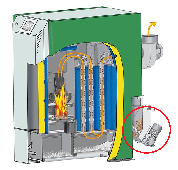
I have circled the part displaying the beginning of the pellet conveyor and the motor.
-
Pellet burner MonitoringI'm following-up on this thread Sensor for pellet burner.
On my side, I have started to monitor my pellet burner about 1-year ago.
I'm measuring global power consumption of the boiler as well as departure and return temperature of the heating circuit.
Even though, I do that since one year only, I've been thinking about how to monitor pellet consumption for at least 5 years (yeah, failure is an option :) ).
What I have tested:- IR sensor on the fan of the pellet convoying motor: it failed because it was too far
- Magnetic sensor on this same fan: same failure for the same reason
- Vibration sensor: the heater vibrates ...all the time :)
Now, I'm about to test something quite simple: mains presence at the convoying motor. This one is quite easy (I will show you how) to design and relates quite easily to the pellet consumption: 1 second equals x grams of pellet.
How do I know the time mains are activating the motor ? Well, a zero-crossing detector.
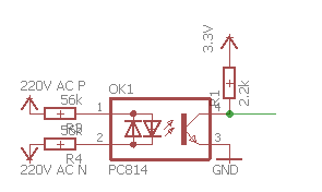
Beware, main resistance values are key: they depend on mains value, optocoupler characteristics and ..their power. Using the displayed value (56k) will keep the power under 1/4W. The optocoupler is a LTV-814 (cheap and efficient !).
Here is a quick schema of such a detector. I will keep you posted with the results.
Hope my experience will help others.
QQ.