Is it OK?
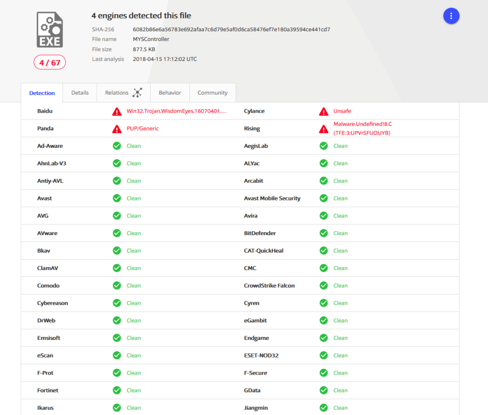
No such warnings/detections for .282 version.
Is it OK?
No such warnings/detections for .282 version.
You can try also Bosch BME280 - all in one sensor for temperature, humidity and pressure
Ikea is also producing zigbee-compatible smart home components (TRÅDFRI series), including led lighting, dimmers, PIRs, ethernet gateways without cloud-based parts (can work w/o internet).
Starting from $11-$19 for dimmers/PIRs here in Poland.
Seems like this is offtopic, but there are good meanwell power supplies designed to run 24x7, like this:
http://www.meanwell.com/webapp/product/search.aspx?prod=DR-15 (MTBF 1.1M hours)
Or even something like this:
http://www.meanwell.com/webapp/product/search.aspx?prod=PM-05 (MTBF 1.5M hours) and so on
I used long time this NFM-05-5 power supplies, very good, no problems at all:
http://www.meanwell.com/webapp/product/search.aspx?prod=NFM-05
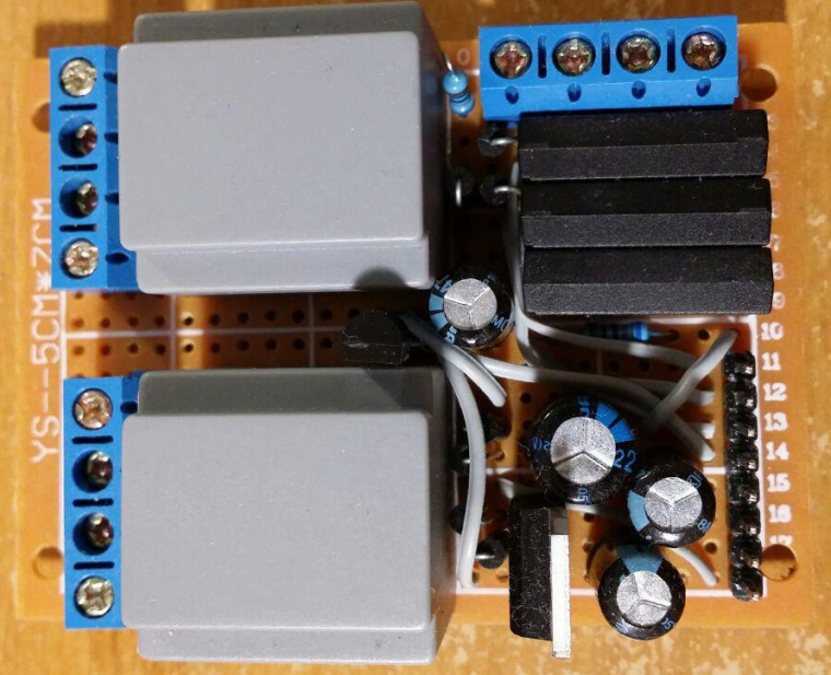
If safety is on the first place you can make your own power supply using miniature transformers like this (lower half of PCB):
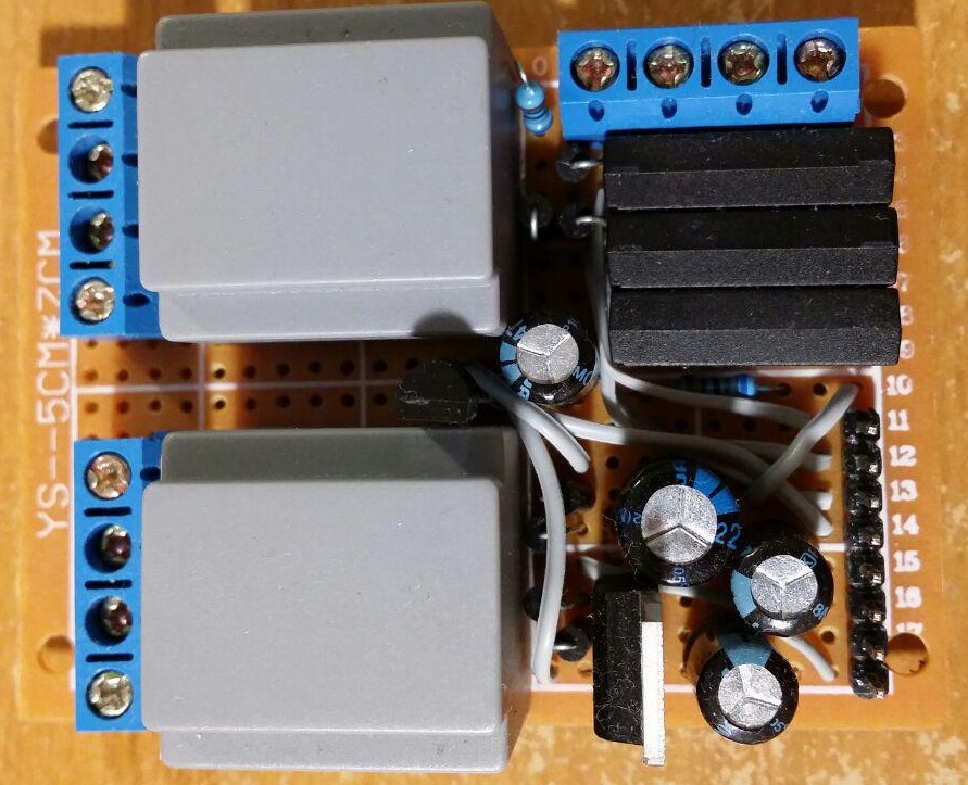
Such transformers are very small for low-power nodes:
UPD: link to the topic: https://forum.mysensors.org/topic/6259/encapsulated-transformers-instead-of-traditional-switching-power-supplies-like-hi-link
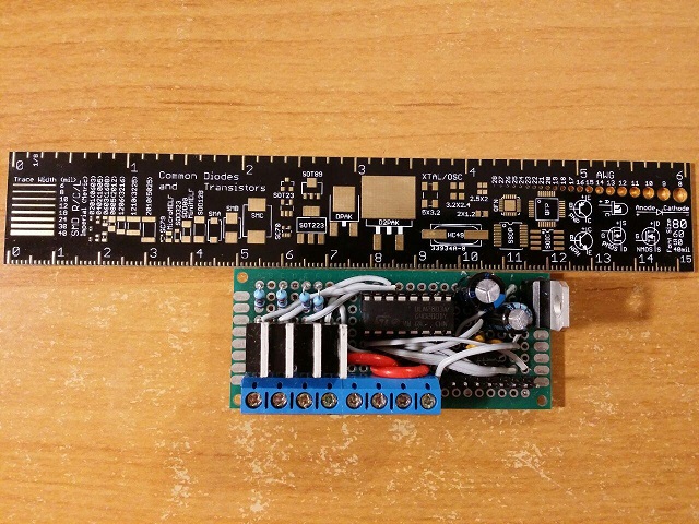
Good ruler, I have such ruler too :)
Today's power part of my RGBW dimmer node (four LED channel PWM inputs, 12V input, +12V sense, +5V, +3.3V outputs). Dimmer is controlled by MySensors and also by conventional Samsung TV remote control (five presets, ability to record color presets, autofade from one preset to another, control of each LED channel brightness, gamma correction and so on).
Try to call Serial.flush(); after each print line, this ensures that all data sent to serial port before next line executed.
Can you post image with connection wires to DS18B20 sensor? Could the problem be that this chip is a fake?
Power (lower half) and external interfaces (upper half) PCB for my "entrance" MySensors node (unregulated voltage, +5V, +3.3V, doorbell detector, electronic door lock status, temperature, etc). I'm using conventional 220V=>6V transformers as main power supply and as simple 220V presence detector for doorbell.
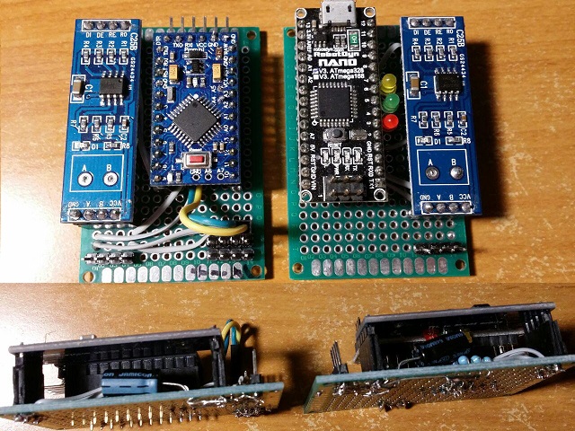
Simple RS485 gateway and node for two BME280 sensors:
Returns true if message reached the first stop on its way to destination
What will be returned in the case of NRF24L01 as gateway's receiver at destination and internal nrf24 buffer is already contains 3 unread messages?
Hello.
How I can change default RX/TX LED blink behavior without modifying MySensors library? I'm talking about serial gateway. Gateway always blink RX and TX LEDs together just because gateway receives (RX) data from serial port and immediately sends (TX) this data to radio network. The same problem happens then gateway receives data from radio.
I just want to blink RX led then something received from radio network and blink TX led then something sent to radio network.
	if ((INDICATION_TX == ind) || (INDICATION_GW_TX == ind)) {
		ledsBlinkTx(1);
	} else
#endif
#if defined(MY_DEFAULT_RX_LED_PIN)
		if ((INDICATION_RX == ind) || (INDICATION_GW_RX == ind)) {
			ledsBlinkRx(1);
		} else
#endif
@rvendrame said in 3.3 or 5v tranformer for mysensors projects:
On the other hand I see the bigger footprint as well as more components to assembly.
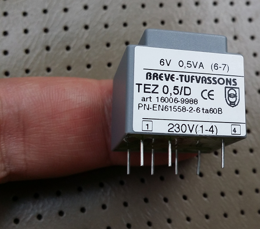
Bigger, but not always. For low-power nodes you can use very small transformers, size of such transformers with rectifier and voltage regulator comparable to Hi-Link PSUs with external curcuity, just an example on my finger:
@m26872 said in Encapsulated transformers instead of traditional switching power supplies like Hi-Link:
for me the sunny season is too short.
I havn't yet tried to use solar batteries in winter so maybe I have the same problems (despite the fact that I'm living 3 degrees south of you), but I have backup solution for very cloudy winter days - regular battery charger.
@m26872 thank you, great review! As far as I understand, no-load power usage is 0.57W (or 1.05W?) vs 1.87W (for small) or 1.76W (for big transformer).
So up to three times more no-load power usage for regular transformers. But in any case overall power usage is still acceptable for me because I sleep better with such transformers :joy:
Now I'm moving to solar-powered sensor nodes where it's possible.
If safety comes first you may be interested in these transformers: https://forum.mysensors.org/topic/6259/encapsulated-transformers-instead-of-traditional-switching-power-supplies-like-hi-link
I'm using such non-electronic transformers and I'm happy.
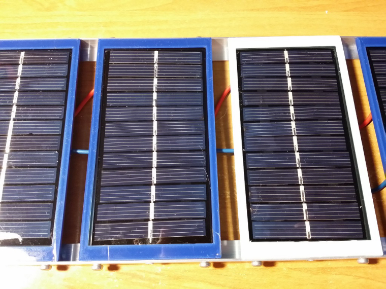
Yet another version and first test results.
Now I'm able to screw panels together using any side:
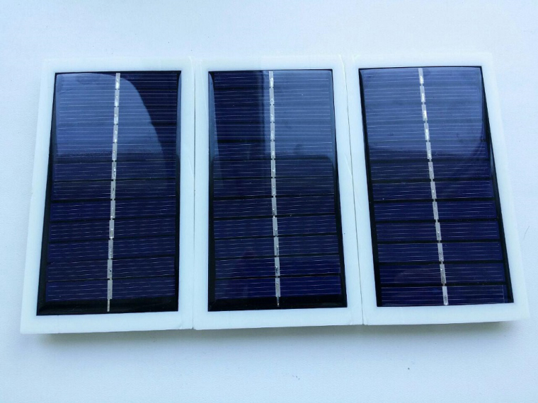
I connected solar panels together (parallel connection, but each panel in series with it's own shottky diode). 11 panels on north side (direct sunlight from about 06:30 up to 09:00) and 5 panels on south side (direct sunlight from about 12:00 up to 19:00). Panels located on window-sill outside of house.
On south side I'm using 6V AGM VRLA acid battery (as far as I remember 4.5 Ah), on north side battery is the same, but battery capacity is 1.3 Ah.
At first I connected panels directly to batteries (panels open-circuit volage is about 6.8-7.5 volts), but I got weird results. When it's sunny and the sky is clear batteries are charging very slowly and then it's cloudy - batteries are charging faster. Scattering of light by clouds?
Then I connected solar panels to step up regulators (mt3608 as far as I remember, output set to 7.0 volts), now I'm getting very good results. Both batteries are charging almost all the day.
Graphs showing step up output voltage (connected directly to battery):
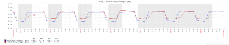
Again, then weather is cloudy batteries are charning a little better.
Also it seems that I have connected too many batteries. It's necessary to try only 1-2 batteries on each side.
Now I'm using simple voltage reporting sketch (5V arduino pro mini, report voltage and smartSleep() every 10 seconds), battery connected directly to RAW pin of arduino. Nothing is changed on hardware and software sides except I removed power led. NRF24L01 using it's own AMS1117-3.3 regulator (consumes a lot of current, about 2mA) connected directly to battery.
Can I use hwCPUVoltage() function to read cpu power supply voltage in my sketch? As far as I understand this function is not documented.
I'm asking because this function affects analogReference(INTERNAL) with further analogRead(pin) call. According to source code it seems for me that hwCPUVoltage() isn't restoring ADC settings before return.
Simple code to test is looking something like this:
void setup()
{
    analogReference(INTERNAL);
}

void loop()
{
    analogRead(pin_number); // good value
    hwCPUVoltage();
    analogRead(pin_number); // bad value
}
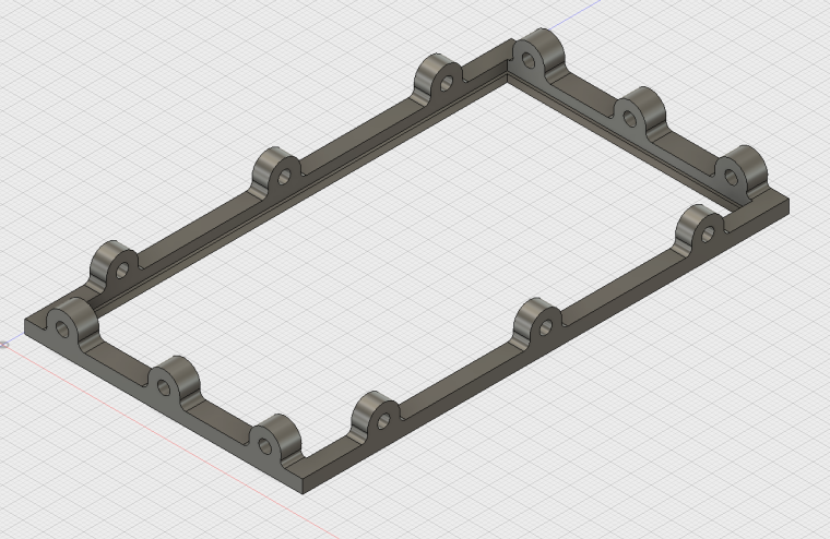
I just published, maybe someone will be interested.
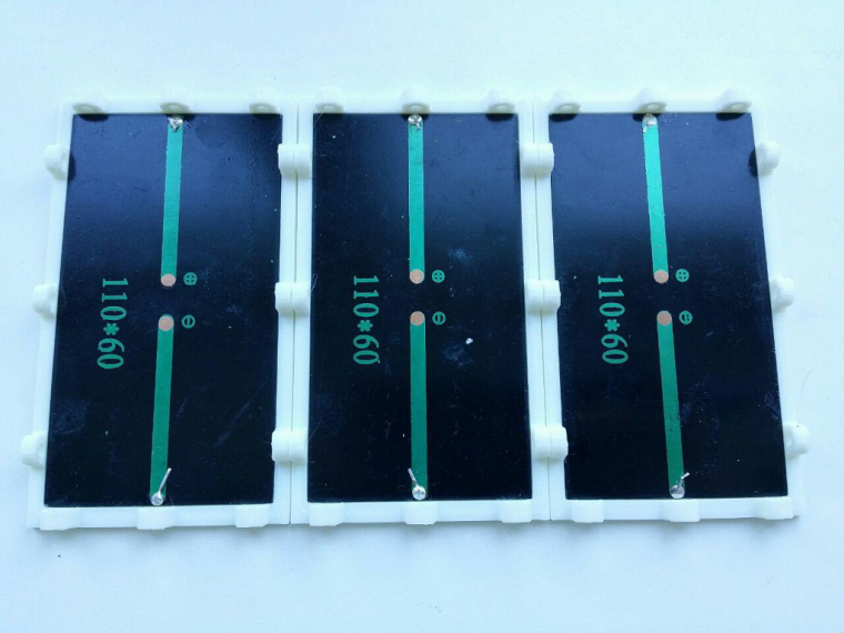
Simple and lightweight 3D-printed solar panel housing for 60x110 mm sized panels widely available on Chinese shops. Three holes on every side for fixing housing allow to fix it in any position/angle. The same holes used to fix solar panel itself in housing.
I'm using cheap ($1/piece) Chinese solar panels.
http://www.thingiverse.com/thing:2303029
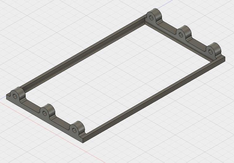
0_1494200102051_SolarHousing2.stl
0_1494200114033_SolarHousing v2.step
Please try to test code with wait() between each send. In some enviroments (not in all) sometimes (not always) ESP code blocks thread of execution up to 200 milliseconds while waiting for TCP ACK packet. So if you send next your packet in this 200 ms interval packet (or next packet) can be missed.
