Navigation

    • Register
    • Login
    • OpenHardware.io
    • Categories
    • Recent
    • Tags
    • Popular
    1. Home
    2. sghazagh
    3. Posts
    • Profile
    • Following
    • Followers
    • Topics
    • Posts
    • Best
    • Groups

    Posts made by sghazagh

    • RE: Mysensors Build Problem on Ubuntu 20.04 (RPi or Tinker Board)

      @sghazagh Hi all,
      I tried to create a empty file and it seems that it does work and does not make any problem for the Radio functionality!

      Any idea what this header is and how can I find this genuine library header for future use?

      touch /usr/include/stropts.h
      
      posted in General Discussion
      sghazagh
      sghazagh
    • Mysensors Build Problem on Ubuntu 20.04 (RPi or Tinker Board)

      Hi all,
      I have problem compiling Mysensors library on Ubuntu 20.04 image running on RPi 3/4 or Tinker Board.

      Getting the error like:

      ...
      e/Linux/drivers/core -c hal/architecture/Linux/drivers/core/Print.cpp -o build/hal/architecture/Linux/drivers/core/Print.o
      g++ -MT build/hal/architecture/Linux/drivers/core/interrupt.o -MMD -MP -DMY_RADIO_RF24 -DMY_GATEWAY_SERIAL -DMY_DEBUG -DLINUX_SPI_SPIDEV -DMY_LINUX_SERIAL_PORT=\"/dev/ttyUSB01\" -DMY_LINUX_SERIAL_IS_PTY  -Ofast -g -Wall -Wextra -std=c++11 -I. -I./core -I./hal/architecture/Linux/drivers/core -c hal/architecture/Linux/drivers/core/interrupt.cpp -o build/hal/architecture/Linux/drivers/core/interrupt.o
      hal/architecture/Linux/drivers/core/interrupt.cpp:33:10: fatal error: stropts.h: No such file or directory
         33 | #include <stropts.h>
            |          ^~~~~~~~~~~
      compilation terminated.
      make: *** [Makefile:99: build/hal/architecture/Linux/drivers/core/interrupt.o] Error 1
      

      It seems that its missing the <stropts.h> header, but have you any idea how I can resolve that?

      Many thanks

      P.S: I tried on both RPI3 and 4 also on Tinker board and the problem are same for all of them running Ubuntu 20.04.

      posted in General Discussion
      sghazagh
      sghazagh
    • RE: Two Mysensors Network in Same Location

      I don't know why, but by adding "--my-rf24-channel=13" in my configuration and compile it again, it seems that all are working as expected now!!!

      ☝ Believe me, I always used "make clean" so don't know why it didn't refresh the build. Perhaps that option force the compiler to rebuild it!!!"

      posted in General Discussion
      sghazagh
      sghazagh
    • RE: Two Mysensors Network in Same Location

      @mfalkvidd I used a LE33 transistor to power up the radio after converting the 5v from Arduino Uno(tried 3.3v pin as well, same).
      I am also using 4.7mF capacitor on positive and negative pols as well.
      I am sure radio is ok, as as soon as I change the Channel back to 76, it quickly register in my first Network.
      When I change the Channel to for instance 13, the GW on channel 13 does not register and see that Node....

      posted in General Discussion
      sghazagh
      sghazagh
    • RE: Two Mysensors Network in Same Location

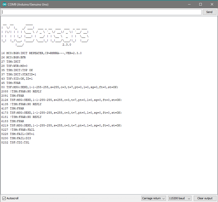
      @mfalkvidd I really don't know what is wrong...I just getting this error all the time
      Cleared the EEPROM first and have set the radio channel to 13 for both GW and Node!)
      0_1538214154962_1.png

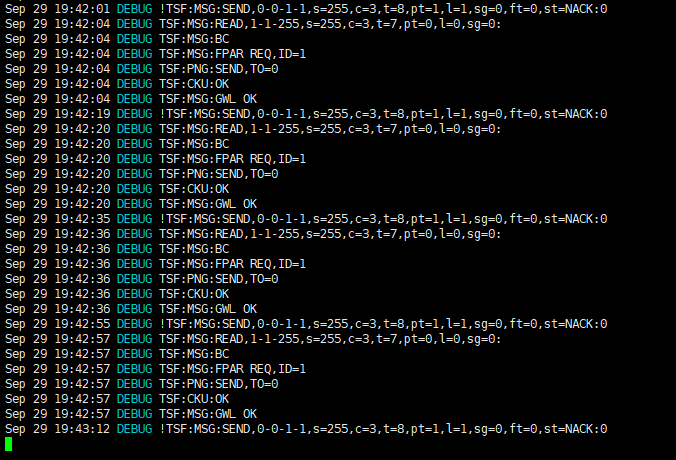
      Here is log on GW side (Serial on Linux)
      0_1538214259675_2.png

      Any idea why they cannot find each other?

      posted in General Discussion
      sghazagh
      sghazagh
    • RE: Two Mysensors Network in Same Location

      @boozz Ok, if we say we have serial GW on Linux and also a Node:

      • Does channel only need to be changed in MyConfig.h file in MySensors Library before I compile for my Serial GW on Linux

      • and for the Node, I only need to add a define in Sktech?

      #ifndef MY_RF24_CHANNEL
      #define MY_RF24_CHANNEL (83)
      #endif
      

      Also have a question about your setting, I see the channels for NRF24L01 only are:

      0 => 2400 Mhz (RF24 channel 1)
      1 => 2401 Mhz (RF24 channel 2)
      76 => 2476 Mhz (RF24 channel 77)
      83 => 2483 Mhz (RF24 channel 84)
      124 => 2524 Mhz (RF24 channel 125)
      125 => 2525 Mhz (RF24 channel 126)
      

      How did you set channel 13 and 58?

      posted in General Discussion
      sghazagh
      sghazagh
    • RE: Two Mysensors Network in Same Location

      @mfalkvidd What you are saying make scenes, because when I start the Node, it goes straight to other Gateway and even when I turn the Network1 Gateway off, it still comes up with Nodeid of Network1but does not register to Network2 Gateway !!!
      I will try it, tomorrow...

      posted in General Discussion
      sghazagh
      sghazagh
    • Two Mysensors Network in Same Location

      Hello all,
      Hope like always you can help me to understand if this concept is possible or not.

      I have an already established MySensor network for my home. So I have controller, nodes (sensors) and all working fine.

      I need to test another device in another MySensor network by running Domoticz and Gateway again.
      So the second server, has Domoticz installed with MySensor Gateway as Serial but cannot communicate with devices properly.
      It seems that having the sensors running in same place, make the system tricky and nodes can register only in one of the networks.
      I tried to resolve this by changing the network channel (from 76 to 83 in MyConfig.h file) for both my second Gateway and a Node I want to use in second network but seems that it's not working as expected either!

      So , can you please any one have this experience, explain that what is the best practice to make it working as two separate MySensors Network in same location please?

      Thanks for your time and hope I could explain the case scenario

      posted in General Discussion
      sghazagh
      sghazagh
    • RE: Question on Mysensors Network with Protected Domoticz Device

      @bjacobse Yes, you are absolutely right, and that password only is required when you trig the device inside controller.
      I mean, if you click the icon in controller for that device and device is protected, it asks for password.
      And if you also use HTTP API, you need to provide password as well.

      So if you want to trig the device from other Mysensor node (my case), it does not know about the protection and you can directly send the message to trig the device on or off.

      posted in General Discussion
      sghazagh
      sghazagh
    • RE: Error compiling gateway for esp8266 node mcu(1.0) e12

      @mfalkvidd when will be the estimate release date of Mysensors library working with esp8266 v2.4.2?

      Getting compile error if I use 2.4.2 library for Lolin d1 mini pro device....

      Thanks

      posted in Troubleshooting
      sghazagh
      sghazagh
    • RE: Question on Mysensors Network with Protected Domoticz Device

      😮 silly me 😄
      It seems that it even doesn't care the device is protected or not! it just could change the status of the device even if it is protected...

      posted in General Discussion
      sghazagh
      sghazagh
    • RE: Question on Mysensors Network with Protected Domoticz Device

      @anticimex At the moment, I have a workaround and doing the logic through the LUA script.
      In LUA, I can send the request to the switch with passcode as I explained above.

      That works fine but that would be great if Mysensor can have an option to send the message directly to controller for particular IDX (like what it does now) plus an option to pass the passcode to controller for protected devices.

      Perhaps, if it's not in the features, that would be good to have it in future releases....

      posted in General Discussion
      sghazagh
      sghazagh
    • RE: Question on Mysensors Network with Protected Domoticz Device

      @anticimex Perhaps I should explain more...

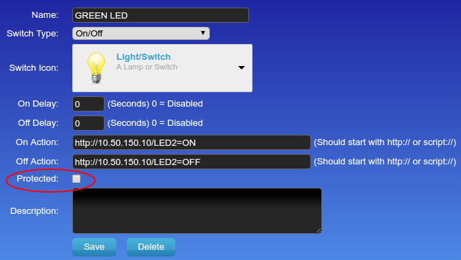
      As you guys know, in Domoticz you can protect a device and set the passcode in setting and use that for devices (Lights, Switches...) to operate if you only provide a correct passcode:
      0_1537421491898_1.png

      If you use Domoticz API to turn the light On or Off, and device is protected, you need to pass a extra parameter in your HTTP request and send the pass code to be able to operate that protected light or switch:
      Something like this:

      /json.htm?type=command&param=switchlight&idx=99&switchcmd=Off&passcode=YOUR_SWITCH_PASSWORD_AS_SET_IN_SETTINGS
      

      Now my question is: how we should send the message from Mysensors device/sensor to Domoticz controller to turn it On or Off if the switch/light is protected?

      posted in General Discussion
      sghazagh
      sghazagh
    • RE: Question on Mysensors Network with Protected Domoticz Device

      @alowhum PROTECTED device a Switch in Domoticz that only can operate if you use a right pass code.

      posted in General Discussion
      sghazagh
      sghazagh
    • Question on Mysensors Network with Protected Domoticz Device

      Hello everyone,
      I have a Mysensors RFID Node running the RFID sketch on Arduino Pro Mini which sends the switch on/off command to Domoticz controller.
      It just works great if the device is not protected.
      I am wondering if I can send the on/off command to a protected device as well.

      Is there any way I send the message to controller to turn the protected device on or off?
      Can you please advise?

      Many thanks

      posted in General Discussion
      sghazagh
      sghazagh
    • RE: Funny charachters at reset

      It seems that I could fix the issue by making the pin 15, LOW at boot time as it triggers the SD BOOT option in ESP8266:

      void setup() {
        pinMode(15, OUTPUT); 
        digitalWrite(15,LOW);
      }
      
      posted in General Discussion
      sghazagh
      sghazagh
    • RE: Funny charachters at reset

      @mfalkvidd Yes, I double checked and it is just before Mysensors.h line.
      I see the Mysensors message in console, however, the radio connection is failing....

      I see in another post , have mentioned that the Mysensors library 2.3.1 or 4.0.0 will be release to resolve the issue we have when compiling for "Lonin D1 Mini Pro" board. Do you know when that gonna happen?
      I afraid maybe the library is mismatching with older version of "Lolin D1 mini pro" which is "Wemos D1 mini pro".

      At the moment I see the name Wemos... in the list of devices in Arduino IDE as I am using esp8266 version 4.2.1.
      Version 4.2.2 of esp8266 is listing the devise as Lolin ... name. I thought maybe the library is not fully compatible with this device as if I use that library the compile won't be successful.
      Do you think that might cause the issue?

      posted in General Discussion
      sghazagh
      sghazagh
    • RE: Funny charachters at reset

      @mfalkvidd

      I read this in forum:

      Ok, after debugging for a while: the problem is with the CSN pin on GPIO pin 15. Pin 15 is also used in the ESP8266 to define boot from SD card. Somehow, at least in my case, after a reset, the NRF chip sets the CSN pin to high (measured it with a multimeter), causing the ESP8266 to start the SD-card procedure, which fails of course. The solution for me is swapping the pins for inclusion with the CSN pin:

      So:
      CSN -> GPIO 5 -> D1
      Inclusion mode -> GPIO 15 -> D78

      One question though: I also seem to have SPI pins on the other side of the Devkit, why aren't those used?```

      That's the one you addressed in GIT.
      I tried to move the CE pin to something else but it seems that it's not working!

      // To use native I2C pins CE should be moved. Declare the new GPIO used here.
      // GPIO 3 is pin D9 (RX below D8)
      #define MY_RF24_CE_PIN D4
      
      posted in General Discussion
      sghazagh
      sghazagh
    • RE: Funny charachters at reset

      All,
      I have changed the baud rate to "74880" as @yveaux mentioned and surprisingly I see this message which prevent the device to boot:

       ets Jan  8 2013,rst cause:2, boot mode:(7,7)
      
      waiting for host
      

      Do you know why it's going to this mode and how can I avoid that?

      posted in General Discussion
      sghazagh
      sghazagh
    • RE: Funny charachters at reset

      @yveaux thanks for your reply,
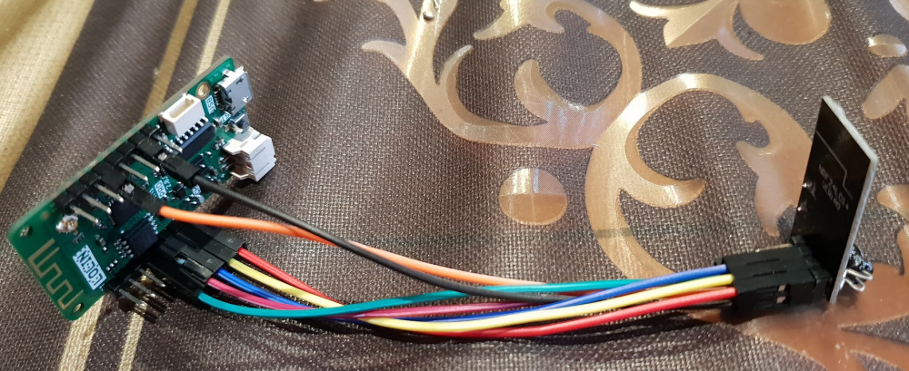
      The radio connected as usual:

      1_1536888951062_2.png
      0_1536888951061_1.png
      0_1536889425869_3.png 0_1536889523085_4.png
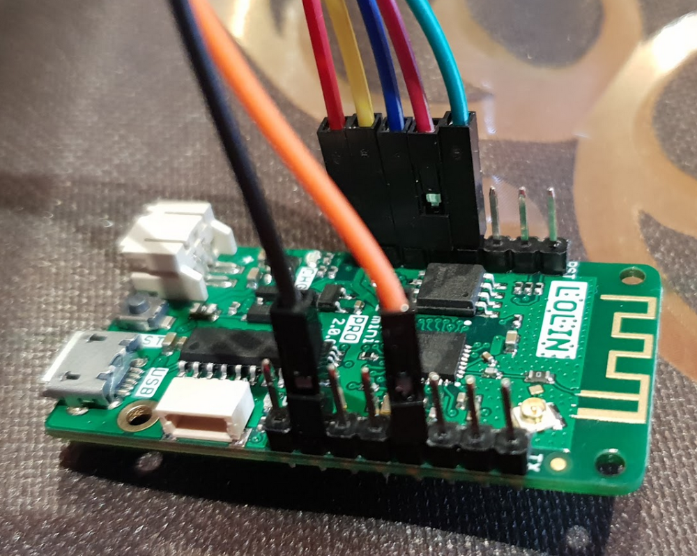
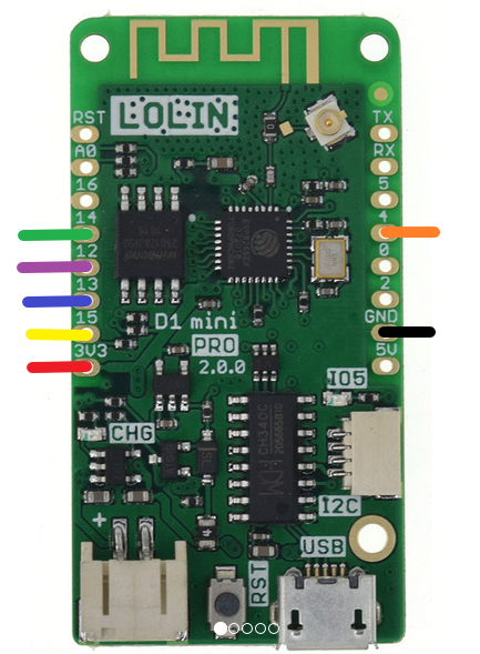
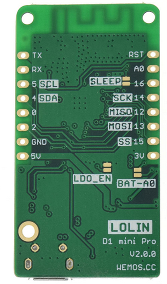
      (All cables used with color coding for better understanding of connection pins)

      I also have changed the different baud rate...it's not that, because at 115200, with radio power disconnected, I can see all the MySensor messages, also when I reconnect the radio power, I can see that the radio can connect to controller and send.receive data!

      Only when radio connected at boot time, device does not boot and does not work properly!

      posted in General Discussion
      sghazagh
      sghazagh
    • Funny charachters at reset

      Hi all,
      I am using Lolin D1 mini pro along with NRF24L01 radio connected.
      I uploaded mysensors relay sketch and whenever the radio is connected, at reset time, I see funny charachters in serial consol preventing the device to come up.
      When I disconnect the radio +3v pin it starts then I have to re-connect the radio power to get it working otherwise it won't work and above problem happens!!!

      Do you guys have any idea why it's happening?

      For your info, the esp8266 library version 4.2.1 is used because as I read in a post, Mysensors won't work with version 4.2.2 and Lolin bored at the moment!

      posted in General Discussion
      sghazagh
      sghazagh
    • RE: MySensor Request Function

      All,
      I leave the code here as it's a working code for getting the Domoticz Virtual Sensor V_TEXT and showing on LCD.
      Just don't forget to:
      disable REPEATER option:

      // #define MY_REPEATER_FEATURE
      

      and remove this line:

      void request(uint8_t childSensorId, uint8_t variableType, uint8_t destination);
      

      Thanks.

      posted in General Discussion
      sghazagh
      sghazagh
    • RE: MySensor Request Function

      @electrik Thanks electrik.
      It is absolutely right, I removed the line for declaring the function and all is working as expected.
      Actually the other problem which made me nut was that I was seeing the device restarts continuously so I thought not declaring the request function is causing that.
      That has fixed as well. The issue was that I had enabled the REPEATER option, however, I didn't add any WIFI library or correct setting for that so the system was crashing and was resetting .
      Now that I disabled that REPEATER option and also did not declaring the request function, all is working fine again.

      @mfalkvidd: I am not sure but believe me it was there and it was compiling just fine before.
      Perhaps used to we had to declare it, and now as "electrik" explained, it already declares in MySensor call.

      Thank you both anyway.
      I think I get it working now.

      Cheers,

      posted in General Discussion
      sghazagh
      sghazagh
    • RE: MySensor Request Function

      @mfalkvidd So what should I do then?

      It was with void before and compiler didn't get any error.
      Isn't it the way to declare it? like other functions?
      ex. void setup(), void presentation(),.... ?????????

      posted in General Discussion
      sghazagh
      sghazagh
    • MySensor Request Function

      All,
      I used to had a sketch to grab the V_TEXT values from Domoticz controller and show on LCD.
      All was good except, recently I wanted to change some of the text on LCD.
      I only changed the text and when I tried to compile the sketch I get some error.

      It does not like this line anymore:

      void request(uint8_t childSensorId, uint8_t variableType, uint8_t destination);
      

      And I receive this set of errors in compiler (Arduino IDE):

      LCD_Sketch:113: error: new declaration 'void request(uint8_t, uint8_t, uint8_t)'
      
       void request(uint8_t childSensorId, uint8_t variableType, uint8_t destination);
      
                                                                                    ^
      
      In file included from C:\Users\Saeid\Documents\Arduino\libraries\MySensors/MySensors.h:412:0,
      
                       from D:\WemosD1MiniPro-NodeMCU-LCD_Sketch\WemosD1MiniPro-NodeMCU-LCD_Sketch.ino:35:
      
      C:\Users\Saeid\Documents\Arduino\libraries\MySensors/core/MySensorsCore.cpp:392:6: error: ambiguates old declaration 'bool request(uint8_t, uint8_t, uint8_t)'
      
       bool request(const uint8_t childSensorId, const uint8_t variableType, const uint8_t destination)
      
            ^
      
      exit status 1
      new declaration 'void request(uint8_t, uint8_t, uint8_t)'
      

      I commented the "void request" line and sketch compile just fine but I feel something is not right.

      • Would you please explain why my code does not compile the code?

      • Is alright to not having the Request line at all?

      • What is your suggestion to get this code improved/fixed as I see the device get restarted after a while on and off!!!

      Here is the full code for my sketch:

       // Enable debug prints to serial monitor
      #define MY_DEBUG 
      
      //Fixed NodeID in Domoticz
      #define MY_NODE_ID 2
      
      // Enable and select radio type attached
      #define MY_RADIO_NRF24
      //#define MY_RADIO_RFM69
      
      // Enable repeater functionality for this node
      #define MY_REPEATER_FEATURE
      
      
      #include <Wire.h> 
      #include <LiquidCrystal_I2C.h>
      #include <SPI.h>
      #include <MySensors.h>
      
      
      // Set the LCD address to 0x27 for a 16 chars and 2 line display
      LiquidCrystal_I2C lcd(0x3F, 20, 4);
      
      //const byte nodeId = 66 ;                   // MySensors fixed node id
      const byte LCD1_CHILD = 8 ;                  // LCD line 1
      const byte LCD2_CHILD = 9 ;                  // LCD line 2
      const byte LCD3_CHILD = 10 ;                 // LCD line 3
      const byte LCD4_CHILD = 11 ;                 // LCD line 4
      
      char lastLCD1[21] = "Line1 - first   ";     // define & init before first receive
      char lastLCD2[21] = "Line2 - second  ";
      char lastLCD3[21] = "Line3 - third   ";     
      char lastLCD4[21] = "Line4 - forth   ";
      
      // Initialize messages for sensor network
      MyMessage textMsg( 0, V_TEXT );
      
      void setup(){
        //WiFi.persistent(false);
        //ESP.flashEraseSector(0x3fe);
        
        Wire.begin(D3, D4);
        lcd.begin();
        lcd.backlight(); // finish with backlight on  
        
      //-------- Write characters on the display ----------------
      // NOTE: Cursor Position: CHAR, LINE) start at 0  
        lcd.setCursor(0,0); //Start at character 4 on line 0
        lcd.print("Welcome to :");
        delay(1000);
        lcd.setCursor(4,1);
        lcd.print("LCD Panel");
        delay(2000); 
        lcd.setCursor(0,3);
        lcd.print("Weather Station");
        delay(2000); 
        lcd.clear();
        
        // Initialize the serial port at a speed of 9600 baud
        Serial.begin(115200);
      }
      
      void presentation()  
      {   
        // Send the sketch version information to the gateway and Controller
        sendSketchInfo("LCD", "2.0");
        
        present(LCD1_CHILD, S_INFO, "LCD_line1");        // new S_type 20150905 (not know by domoticz)
        present(LCD2_CHILD, S_INFO, "LCD_line2");
        present(LCD3_CHILD, S_INFO, "LCD_line3");
        present(LCD4_CHILD, S_INFO, "LCD_line4");
        
        send(textMsg.setSensor(LCD1_CHILD).set("-"));    // initialize the V_TEXT at controller for sensor to none (trick for Domoticz)
        send(textMsg.setSensor(LCD2_CHILD).set("-"));   
        send(textMsg.setSensor(LCD3_CHILD).set("-")); 
        send(textMsg.setSensor(LCD4_CHILD).set("-")); 
      
        //requestTime(); 
      
          lcd.clear();
          lcd.setCursor(0, 0);
          lcd.print("Inside  (T):");
      
          lcd.setCursor(0, 1);
          lcd.print("Outside (T):");
      
          lcd.setCursor(0, 2);
          lcd.print("Bedroom (T):");
      
          lcd.setCursor(0, 3);
          lcd.print("Bedroom (H):");
      }
      
      void requestTime();
      
      void request(uint8_t childSensorId, uint8_t variableType, uint8_t destination);
      
      
      void loop(){
        
        Serial.println(".");
        //requestTime();
        request(8,V_TEXT,0);
        wait(50);
        request(9,V_TEXT,0);
        wait(50); 
        request(10,V_TEXT,0);
        wait(50); 
        request(11,V_TEXT,0);
        wait(50); 
        sleep(60000);
        
        // If characters arrived over the serial port...
        if (Serial.available()) {
          // Wait a bit for the entire message to arrive
          delay(100);
          // Clear the screen
          lcd.clear();
          
      
          // Write all characters received with the serial port to the LCD.
          while (Serial.available() > 0) {
            lcd.write(Serial.read());
          }
        }
        
      }
      
      // This is called only if new time value was received by calling requestTime();
      void receiveTime(unsigned long controllerTime) {
          Serial.print("Time value received: ");
          Serial.println(controllerTime);
      
          //Hours = controllerTime / (1000*60*60)
          //Minutes = (controllerTime % (1000*60*60)) / (1000*60)
          //Seconds = ((controllerTime % (1000*60*60)) % (1000*60)) / 1000
          
          lcd.clear();
          lcd.setCursor(0, 0);
          lcd.print("Current Time");
          lcd.setCursor(0,1);
          lcd.print(controllerTime);  //seconds format ex. 45681238785
       }
      
      // This is called when a message is received 
      void receive(const MyMessage &message) {
      
         // Write some debug info
         Serial.print("Message: "); 
         Serial.print(message.sensor); 
         Serial.print(", Message: "); 
         Serial.println(message.getString());
      
          lcd.setCursor(0, 0);
          lcd.print("Inside  (T):");
      
          lcd.setCursor(0, 1);
          lcd.print("Outside (T):");
      
          lcd.setCursor(0, 2);
          lcd.print("Bedroom (T):");
      
          lcd.setCursor(0, 3);
          lcd.print("Bedroom (H):");
           
        if (message.type==V_TEXT) {
          if (message.sensor == LCD1_CHILD ) {
            //snprintf(lastLCD1, sizeof(lastLCD1), "%20s", message.getString());  // load text into LCD string
            //lcd.setCursor(17, 1);
            //lcd.print(lastLCD1);
            lcd.setCursor(13, 0);
            lcd.print(message.getString());
            lcd.print((char)223);
            lcd.print("C"); 
          } 
         if (message.sensor == LCD2_CHILD ) {
             lcd.setCursor(0, 1);
            //lcd.print(lastLCD2);
              lcd.setCursor(13, 1);
              lcd.print(message.getString());
              lcd.print((char)223);
              lcd.print("C"); 
         }
         if (message.sensor == LCD3_CHILD ) {
             lcd.setCursor(0, 2);
            //lcd.print(lastLCD3);
              lcd.setCursor(13, 2);
              lcd.print(message.getString());
              lcd.print((char)223);
              lcd.print("C"); 
         }
        if (message.sensor == LCD4_CHILD ) {
             lcd.setCursor(0, 3);
            //lcd.print(lastLCD4);
              lcd.setCursor(13, 3);
              lcd.print(message.getString());
              lcd.print("%"); 
         }
         } 
      }
      

      P.S: I am using MySensor Library 2.3.0 hwever, by reverting it back to 2.2.0, problem still persist.
      I am also using NodeMCU v1.0 for my microprocessor connected to LCD and NRF24 Radio.

      posted in General Discussion
      sghazagh
      sghazagh
    • RE: Battery Operated Door Magnet Sensor

      @carmelo42 Yes, I did.
      See this page: https://forum.mysensors.org/topic/486/my-2aa-battery-sensor (Edit 2 image)
      I used this as a base. Except, instead of DH22, I used magnetic sensor connected to pin 3 and GND of Arduino Pro mini.

      posted in My Project
      sghazagh
      sghazagh
    • RE: Battery Operated Door Magnet Sensor

      @m26872 Thank you very much mate.
      I just added the battery reporting part and it works like a charm.

      Many many thanks...

      posted in My Project
      sghazagh
      sghazagh
    • Battery Operated Door Magnet Sensor

      Hi guys,
      I have created a circuit base on this "https://forum.mysensors.org/topic/486/my-2aa-battery-sensor" and it works fine.
      However, I have changed the code slightly to only read the battery state to calculated the battery percentage only when status of door switch changed.

      I know I have to sleep the arduino and radio to save battery but don't know where I have sleep it.
      My code is attached can you please advise me how can I change the code to be able to read the status of door change as quick as possible without delay and also be able to read/calculate battery percentage as well.

      here is my code:

      /**
         The MySensors Arduino library handles the wireless radio link and protocol
         between your home built sensors/actuators and HA controller of choice.
         The sensors forms a self healing radio network with optional repeaters. Each
         repeater and gateway builds a routing tables in EEPROM which keeps track of the
         network topology allowing messages to be routed to nodes.
      
         Created by Henrik Ekblad <henrik.ekblad@mysensors.org>
         Copyright (C) 2013-2015 Sensnology AB
         Full contributor list: https://github.com/mysensors/Arduino/graphs/contributors
      
         Documentation: http://www.mysensors.org
         Support Forum: http://forum.mysensors.org
      
         This program is free software; you can redistribute it and/or
         modify it under the terms of the GNU General Public License
         version 2 as published by the Free Software Foundation.
      
       *******************************
      
         DESCRIPTION
      
         Simple binary switch example
         Connect button or door/window reed switch between
         digitial I/O pin 3 (BUTTON_PIN below) and GND.
         http://www.mysensors.org/build/binary
      */
      
      
      // Enable debug prints to serial monitor
      #define MY_DEBUG
      
      //Fixed NodeID in Domoticz
      #define MY_NODE_ID 8
      
      // Enable and select radio type attached
      #define MY_RADIO_NRF24
      //#define MY_RADIO_RFM69
      
      #include <SPI.h>
      #include <MySensors.h>
      #include <Bounce2.h>
      
      #define CHILD_ID 5
      #define BUTTON_PIN  3  // Arduino Digital I/O pin for button/reed switch
      
      Bounce debouncer = Bounce();
      int oldValue = -1;
      
      int BATTERY_SENSE_PIN = A0;  // select the input pin for the battery sense point
      
      unsigned long SLEEP_TIME = 900000;  // sleep time between reads (seconds * 1000 milliseconds)
      int oldBatteryPcnt = 0;
      
      // Change to V_LIGHT if you use S_LIGHT in presentation below
      MyMessage msg(CHILD_ID, V_TRIPPED);
      
      void setup()
      {
      
        // use the 1.1 V internal reference
        #if defined(__AVR_ATmega2560__)
          analogReference(INTERNAL1V1);
        #else
          analogReference(INTERNAL);
        #endif
      
        // Setup the button
        pinMode(BUTTON_PIN, INPUT);
        // Activate internal pull-up
        digitalWrite(BUTTON_PIN, HIGH);
      
        // After setting up the button, setup debouncer
        debouncer.attach(BUTTON_PIN);
        debouncer.interval(5);
      }
      
      void presentation() {
        // Send the sketch version information to the gateway and Controller
        sendSketchInfo("Enterance-Door-Sensor", "1.0");
      
        // Register binary input sensor to gw (they will be created as child devices)
        // You can use S_DOOR, S_MOTION or S_LIGHT here depending on your usage.
        // If S_LIGHT is used, remember to update variable type you send in. See "msg" above.
        present(CHILD_ID, S_DOOR);
      }
      
      
      //  Check if digital input has changed and send in new value
      void loop()
      {
        debouncer.update();
        // Get the update value
        int value = debouncer.read();
      
        if (value != oldValue) {
          // Send in the new value
          send(msg.set(value == HIGH ? 1 : 0));
          oldValue = value;
          BatteryMeasurment();
        }
       ////// sleep(SLEEP_TIME);    //Can I add it here, in this case does the door sensor response quickly to any state change?
      }
      
      void BatteryMeasurment(){
          
        // get the battery Voltage
        int sensorValue = analogRead(BATTERY_SENSE_PIN);
        #ifdef MY_DEBUG
          Serial.println(sensorValue);
        #endif
        
          // 1M, 470K divider across battery and using internal ADC ref of 1.1V
          // Sense point is bypassed with 0.1 uF cap to reduce noise at that point
          // ((1e6+470e3)/470e3)*1.1 = Vmax = 3.44 Volts
          // 3.44/1023 = Volts per bit = 0.003363075
        
          int batteryPcnt = sensorValue / 10;
        
        #ifdef MY_DEBUG
          float batteryV  = sensorValue * 0.003363075;
          Serial.print("Battery Voltage: ");
          Serial.print(batteryV);
          Serial.println(" V");
        
          Serial.print("Battery percent: ");
          Serial.print(batteryPcnt);
          Serial.println(" %");
        #endif
        
          if (oldBatteryPcnt != batteryPcnt) {
            // Power up radio after sleep
            sendBatteryLevel(batteryPcnt);
            oldBatteryPcnt = batteryPcnt;
          }
      
      }


      If it's wrong, how can I attach the pin 3 , which is door contact switch pin, to an interrupt to responds as soon as state changes?
      Please note that the radio IRQ is connected to pin 2 of Arduino already!

      Many thanks,

      posted in My Project
      sghazagh
      sghazagh
    • RE: MySensors EEPROM save/load Position

      @Yveaux
      I have shifted the saving address from 0 to 10 and it seems that it is working now.
      I have updated the GIT so a guy is looking at it.
      It definitely has some conflict with address between 0~10 as all other data saving somewhere else can be restored properly!
      Still don't understand why mysensors writes something on these addresses!!!

      posted in Development
      sghazagh
      sghazagh
    • RE: MySensors EEPROM save/load Position

      @Yveaux : It gave me a clue!
      In file EepromAddress.h I found this:

      #ifndef MyEepromAddresses_h
      #define MyEepromAddresses_h
      // EEPROM start address for mysensors library data
      #define EEPROM_START 0
      // EEPROM location of node id
      #define EEPROM_NODE_ID_ADDRESS EEPROM_START
      // EEPROM location of parent id
      #define EEPROM_PARENT_NODE_ID_ADDRESS (EEPROM_START+1)
      // EEPROM location of distance to gateway
      #define EEPROM_DISTANCE_ADDRESS (EEPROM_PARENT_NODE_ID_ADDRESS+1)
      #define EEPROM_ROUTES_ADDRESS (EEPROM_DISTANCE_ADDRESS+1) // Where to start storing routing information in EEPROM. Will allocate 256 bytes.
      #define EEPROM_CONTROLLER_CONFIG_ADDRESS (EEPROM_ROUTES_ADDRESS+256) // Location of controller sent configuration (we allow one payload of config data from controller)
      #define EEPROM_FIRMWARE_TYPE_ADDRESS (EEPROM_CONTROLLER_CONFIG_ADDRESS+24)
      #define EEPROM_FIRMWARE_VERSION_ADDRESS (EEPROM_FIRMWARE_TYPE_ADDRESS+2)
      #define EEPROM_FIRMWARE_BLOCKS_ADDRESS (EEPROM_FIRMWARE_VERSION_ADDRESS+2)
      #define EEPROM_FIRMWARE_CRC_ADDRESS (EEPROM_FIRMWARE_BLOCKS_ADDRESS+2)
      #define EEPROM_SIGNING_REQUIREMENT_TABLE_ADDRESS (EEPROM_FIRMWARE_CRC_ADDRESS+2)
      #define EEPROM_WHITELIST_REQUIREMENT_TABLE_ADDRESS (EEPROM_SIGNING_REQUIREMENT_TABLE_ADDRESS+32)
      #define EEPROM_SIGNING_SOFT_HMAC_KEY_ADDRESS (EEPROM_WHITELIST_REQUIREMENT_TABLE_ADDRESS+32) // This is set with SecurityPersonalizer.ino
      #define EEPROM_SIGNING_SOFT_SERIAL_ADDRESS (EEPROM_SIGNING_SOFT_HMAC_KEY_ADDRESS+32) // This is set with SecurityPersonalizer.ino
      #define EEPROM_RF_ENCRYPTION_AES_KEY_ADDRESS (EEPROM_SIGNING_SOFT_SERIAL_ADDRESS+9) // This is set with SecurityPersonalizer.ino
      #define EEPROM_NODE_LOCK_COUNTER (EEPROM_RF_ENCRYPTION_AES_KEY_ADDRESS+16)
      #define EEPROM_LOCAL_CONFIG_ADDRESS (EEPROM_NODE_LOCK_COUNTER+1) // First free address for sketch static configuration
      

      With quick calculation I think the first free address would be 157? correct? (can you please check and see if you come up with same result)

      If thats the case, then I have to rewrite my code and fit them from address 157 to 256. What do you think?

      posted in Development
      sghazagh
      sghazagh
    • RE: MySensors EEPROM save/load Position

      @Yveaux : Many thanks for your reply.

      I don't think if it overflow. from 206 to 256 all are spaces which the MySensor can use unless it's hard coded to start from 0 or something like that.

      I don't know if MySensors writes something on eeprom without our request (unless we ask for 'saveState' or other commands uses eeprom), otherwise, that's not good, as we need to maintain the eeprom space by our applications and it makes conflict.

      I will post it on GIT as issue and hope the proper answer comes up.

      Thanks again,

      posted in Development
      sghazagh
      sghazagh
    • MySensors EEPROM save/load Position

      Hi guys,
      I have created a sensor which working fine with my Controller.
      I also have implemented webserver on my board (Wemos D1 mini Pro) to have control on sensor over the web as well.
      So it gives me option to access to the webserver on the board directly to control the sensor if for some reason controller was offline.

      For my webserver, I made it dynamic and saving SSID, Password and static IP, Gateway , Subnet Mask addresses into the eeprom start from position 0 and uses up to address 205.

      I also need to save and load MySensor relay state on eeprom. So, i have set the position to save on location 206 (one bit after my webserver settings).
      But it always writes on position 0 so it mess up my settings on that location.

      Can you please guide me why the "saveState(206, message.getBool());" does not save the status on address that I have specified?

      Note: I also use "loadState(206);" to retrieve the status. It also reads it from same position that saveSate eas used. (So it's working but my webserver settings does get mess and will not have proper values if I use load/saveState function)

      Hope I could explained well!
      Many thanks,

      posted in Development
      sghazagh
      sghazagh
    • RE: 💬 Building a WiFi Gateway using ESP8266

      Guys, just an update for my issue regarding Radio and my circuit.
      The Radio was faulty, I received the new one, swapped it and all worked fine.

      I just posted that here if someone want to use my last post image as a reference for connecting the Radio.
      The wiring all are correct.

      Thanks

      posted in Announcements
      sghazagh
      sghazagh
    • RE: Extending the Range of MySensor GateWay

      Hi,
      Thanks for your answers.
      This one made me curious : "The wemos/esp8266 can be used as a wifi gateway or as a repeater with non-wifi radio."

      Do you mean for Wemos D1, I do not need to attach Radio and it still can be used as a Node?

      posted in Development
      sghazagh
      sghazagh
    • Extending the Range of MySensor GateWay

      Hi guys,
      Have a question about Mysensors.
      I have a Raspberry Pi 2 loading Domotics and GateWay uses native GPIO of Raspberry.
      I also have a Node with in 5-7 meter distance which works fine.
      My house is double story and I tried to test the access from far corner of second floor and have realized that the GateWay is not in range!

      My questions are:

      • What is the best solution to extend the range
      • Can I use repeater to act to send and receive messages between GW and Nodes? Is that what the repeater does?
      • I am using "Wemos D1 Mini Pro version" as my nodes and wanna use it as repeater or maybe WiFI Gateway, whatever is right.Can I do that to extend the broadcasting of messages for further distances from main GatwWay?
      • The sample MySensors code does not compile if I enable the IP of GateWay to make the wifiGateway acts as client.
        Is there any guide help me to set it up if the Repeater/ESP8266 WiFiGateWay is the answer.

      Many thanks for your help

      posted in Development
      sghazagh
      sghazagh
    • RE: 💬 Building a WiFi Gateway using ESP8266

      Good idea,
      Here is the side by side image from front and back of the PCB.
      The 'j1' marked on wrong pin ,that's why I think my radio is not working at all as it seems it's very bad replicate.
      However, I have rotated it by 180 degree and tried that as well. same result!

      0_1478323600970_radio.png

      posted in Announcements
      sghazagh
      sghazagh
    • RE: 💬 Building a WiFi Gateway using ESP8266

      I used the same link (pins and sketches!). Checked it 10 times!
      I think my Radios are not functional....

      posted in Announcements
      sghazagh
      sghazagh
    • RE: 💬 Building a WiFi Gateway using ESP8266

      Hi all,
      I try to connect the Radio to Wemos D1 mini Pro and it's not working? I used both ESP8266Gateway and RelayActuator sketches and both Radio Fails...
      Are the pins here work fine with Wemos D1Mini?here is the pinout: http://escapequotes.net/wp-content/uploads/2016/02/d1-mini-esp8266-board-sh_fixled.jpg

      And here is the error I get:
      TSM:INIT
      !TSM:RADIO:FAIL
      !TSM:FAILURE
      TSM:PDT

      thanks,

      posted in Announcements
      sghazagh
      sghazagh
    • RE: MySensors Communication

      I think I was wrong!
      I saw the post you gave and I also see this error:

      0;255;3;0;9;TSM:PDT
      0;255;3;0;9;TSM:INIT
      0;255;3;0;9;!TSM:RADIO:FAIL
      0;255;3;0;9;!TSM:FAILURE
      0;255;3;0;9;TSM:PDT

      So the Radio is required even if the NodeMCU itself has ESP8266 on board. Correct?

      posted in My Project
      sghazagh
      sghazagh
    • RE: MySensors Communication

      Hi,
      Thank you for your reply.
      I had seen that page before but I thought it is saying that I need to connect a Radio to NodeMCU.

      Now that you mentioned the possibility and the link, I just have realized that the color showing on NodeMCU in fact try to show the identical Radio GPIOs on NodeMCU and it's not about connecting those two together.Am I correct?

      So it make sense now!

      The page is a little bit confusing. For newbies like me it some sort telling that you need to connect the GPIOs on NodeMCU identified by colors, to the Radio Module!

      Just please confirm if I got your point correctly then I will try to use my NodeMCU/Wemos D1 mini device to see if I can set it up as a Gateway.

      Once again, many thanks for your reply.

      posted in My Project
      sghazagh
      sghazagh
    • MySensors Communication

      Hello guys,
      I am new in MySensors devices communicating with Controllers.
      So a question raised for me which hope you guys can clear that for me.

      I see the sketches for MySensor (Devices) uses Arduino boards without WIFI module and then uses Radiolink (ex. NLF24L01) to communicate through WiFi/wireless.

      My question is that, do we still need to use Radio link for devises which they already have WIFI ?
      For instance NodeMCU and Wemos Di mini for example have the WIFI ESP8266 on board.
      Can we use that for sending the messages to controller or we have to use another WiFi radio like NLF24L01 to communicate with controllers?

      Many thanks,

      posted in My Project
      sghazagh
      sghazagh