Navigation

    • Register
    • Login
    • OpenHardware.io
    • Categories
    • Recent
    • Tags
    • Popular
    1. Home
    2. Tigroenot
    3. Posts
    • Profile
    • Following
    • Followers
    • Topics
    • Posts
    • Best
    • Groups

    Posts made by Tigroenot

    • RE: Sensebender Micro Battery Code

      @rozpruwacz said in Sensebender Micro Battery Code:

      @Tigroenot said in Sensebender Micro Battery Code:

      consumption

      OK, i upload my code to github and share it with all, but I must warn that it is work in progress and it will change a lot and is not tested very well (just on my 3 different sensors).
      @Tigroenot 3uA ? hehe 😛 my multimeter showed 4uA on 2000uA range (the lowest i have) for a door/window sensor (atmega + nrf24 + battery voltage divider + pull up resistor on one of the gpios + all powered with directly from cr2032 battery), but probably the measurement error is significant ...

      No error, it's just a matter of faith 🙂

      posted in Development
      Tigroenot
      Tigroenot
    • RE: Sensebender Micro Battery Code

      @rozpruwacz Sure, please share. It will all help a lot to see from the other perspective all the smart lifehucks and to finally get to desirable 3uA sleep consumption 🙂

      posted in Development
      Tigroenot
      Tigroenot
    • RE: 💬 RFM69 Livolo 2 channels 1 way EU switch(VL-C700X-1_Ver_C2)

      @tonnerre33 well, the reason for that is that livolo switch power circuit board contains two power circuits 🙂
      One is a standby power which feeds the MC while all lamps are off and another one is the circuit that powers the whole system while at least one of the lamps is on (for two lamps switch).

      posted in OpenHardware.io
      Tigroenot
      Tigroenot
    • RE: Sensebender Micro Battery Code

      Here it is. link

      Hope it will help.

      posted in Development
      Tigroenot
      Tigroenot
    • RE: Sensebender Micro Battery Code

      @meddie As far as I'm concerned you should use the sleep() function. Also it's a good idea to use internal oscillator down to 1mhz and set the BOD to 1,8v. Also I think reading the temperature and humidity once in 5-10 minutes is enough,and transmit if it changes. There is a thread of the forum about cr2032 temperature node.

      posted in Development
      Tigroenot
      Tigroenot
    • RE: Node doesn't work without repeater

      Well, what I did is swaped the radio on the gateway, added capacitors (10-200uf), swaped the nrf chip on the nodes (nrf+ and nrf), added 1M resistor to the node for radio back compatibility, moved nodes closer to the gateway and further from it, flashed the repeater node (now it's node 10 again) with repeater function disabled.

      In the end, I've got three new nodes that talk to controller ONLY through repeater node (the repeater node is further from the gateway then the new nodes). Clearing the routing table on the repeater node doesn't help, erasing eeprom of the repeater node makes it change the node ID and after restarting the other nodes they bind to the repeater again.
      Strange thing is that the node 10 is with MYSBootloader (which has nrf chanel 76 set) and it talks straight to the gateway. The nodes (8,12,13) have the same bootloader and nrf chanel set to 76 and are not recognised by the gateway as soon as there is no repeater node 10.

      posted in Troubleshooting
      Tigroenot
      Tigroenot
    • RE: Node doesn't work without repeater

      @gohan said in Node doesn't work without repeater:

      Did you restarted the gateway so that all nodes presented again? It is actually kind of weird since quite some people had issues about the nodes trying to connect to low signal gateway even if repeater had better signal.

      Not only have I restarted the gateway, I have reinstalled it, now it's latest development branch.
      Now I have built one more node, burned the same 1.3 MYSBootloader, and it doesn't show up on the network at all. Static parent ID and set node ID don't do a thing.

      314689 TSF:MSG:SEND,255-255-255-255,s=255,c=3,t=7,pt=0,l=0,sg=0,ft=0,st=OK:
      316700 !TSM:FPAR:NO REPLY
      316702 TSM:FPAR
      

      The gateway works normally, it gets the data from similar nodes that are further that this new one... I'm very confused...

      Maybe it's somethig to do with the nrf chanels? MYSBootloader? All my nodes are the same...

      posted in Troubleshooting
      Tigroenot
      Tigroenot
    • RE: Node doesn't work without repeater

      The range is not the issue because I tried to move it closer to the gateway, but untill I power on the repeater node it didn't work.

      I sent C_INTERNAL, I_DEBUG, E to node 10, is has reset it's ID and became no 11, and after that nodes 2 and 12 starter to work through node 11. Damn it. I reset the ID of node 2, it became node 8 and continued to work through node 11. Sh*t!
      Now I've got two nodes that just want that bloody repeater node 11 and don't want to deal with the filthy gateway 🙂

      posted in Troubleshooting
      Tigroenot
      Tigroenot
    • RE: Node doesn't work without repeater

      0_1493559720612_Screen.png

      posted in Troubleshooting
      Tigroenot
      Tigroenot
    • RE: Node doesn't work without repeater

      @sundberg84 said in Node doesn't work without repeater:

      @Tigroenot said in Node doesn't work without repeater:

      Please, explain it to me, shouldn't the node find another parent if the repeater is offline?

      It should - and I think the limit (was before atleast) is 6 failed messages and the it should search a new way/route.

      It looks like it does try to find a new way (2-2-255 instead of 2-2-10) but doesnt get a reply. Maybe the routing table in the GW still is going trhough the repeater?

      The repeater is fisically off. I can see the routing table through the MYSController. Tried to clear it - doesn't seem to work.

      Here is another attempt. I downloaded the latest stable 2.1.1 and here is the output:

      0 MCO:BGN:INIT NODE,CP=RNNNA--,VER=2.1.1
      4 TSM:INIT
      4 TSF:WUR:MS=0
      12 TSM:INIT:TSP OK
      14 TSF:SID:OK,ID=2
      16 TSM:FPAR
      16 TSM:FPAR:STATP=0
      18 TSM:ID
      20 TSM:ID:OK
      20 TSM:UPL
      59 !TSF:MSG:SEND,2-2-0-0,s=255,c=3,t=24,pt=1,l=1,sg=0,ft=0,st=NACK:1
      2066 TSM:UPL
      2103 !TSF:MSG:SEND,2-2-0-0,s=255,c=3,t=24,pt=1,l=1,sg=0,ft=1,st=NACK:1
      4112 TSM:UPL
      4149 !TSF:MSG:SEND,2-2-0-0,s=255,c=3,t=24,pt=1,l=1,sg=0,ft=2,st=NACK:1
      6158 TSM:UPL
      6195 !TSF:MSG:SEND,2-2-0-0,s=255,c=3,t=24,pt=1,l=1,sg=0,ft=3,st=NACK:1
      8204 !TSM:UPL:FAIL
      
      475289 TSM:FPAR
      475291 TSM:FPAR:STATP=0
      475293 TSM:ID
      475295 TSM:ID:OK
      475297 TSM:UPL
      475334 !TSF:MSG:SEND,2-2-0-0,s=255,c=3,t=24,pt=1,l=1,sg=0,ft=8,st=NACK:1
      475770 TSF:MSG:READ,12-12-255,s=255,c=3,t=7,pt=0,l=0,sg=0:
      475779 TSF:MSG:BC
      477343 TSM:UPL
      477380 !TSF:MSG:SEND,2-2-0-0,s=255,c=3,t=24,pt=1,l=1,sg=0,ft=9,st=NACK:1
      477872 TSF:MSG:READ,12-12-255,s=255,c=3,t=7,pt=0,l=0,sg=0:
      477878 TSF:MSG:BC
      479389 TSM:UPL
      479426 !TSF:MSG:SEND,2-2-0-0,s=255,c=3,t=24,pt=1,l=1,sg=0,ft=10,st=NACK:1
      479977 TSF:MSG:READ,12-12-255,s=255,c=3,t=7,pt=0,l=0,sg=0:
      479983 TSF:MSG:BC
      481435 TSM:UPL
      481472 !TSF:MSG:SEND,2-2-0-0,s=255,c=3,t=24,pt=1,l=1,sg=0,ft=11,st=NACK:1
      483481 !TSM:UPL:FAIL```
      posted in Troubleshooting
      Tigroenot
      Tigroenot
    • RE: Node doesn't work without repeater

      Please, explain it to me, shouldn't the node find another parent if the repeater is offline? Shouldn't the gateway reply to FPAR request? The range is really not the issue because I've got a PA+LNA nrf module on the gateway, and it is 4 meters away from the node 2.
      Maybe I should move to the stable branch? 🙂

      posted in Troubleshooting
      Tigroenot
      Tigroenot
    • RE: Node doesn't work without repeater

      @sundberg84 Adn here is the serial output of the node 2 when the repeater node 10 is off:

      Here is the serial output of the node 2 when the repeater node 10 is off:

      0 MCO:BGN:INIT NODE,CP=RNNNA--,VER=2.1.0-beta
      4 TSM:INIT
      4 TSF:WUR:MS=0
      12 TSM:INIT:TSP OK
      14 TSF:SID:OK,ID=2
      16 TSM:FPAR
      53 TSF:MSG:SEND,2-2-255-255,s=255,c=3,t=7,pt=0,l=0,sg=0,ft=0,st=OK:
      2060 !TSM:FPAR:NO REPLY
      2062 TSM:FPAR
      2099 TSF:MSG:SEND,2-2-255-255,s=255,c=3,t=7,pt=0,l=0,sg=0,ft=0,st=OK:
      4108 !TSM:FPAR:NO REPLY
      4110 TSM:FPAR
      4147 TSF:MSG:SEND,2-2-255-255,s=255,c=3,t=7,pt=0,l=0,sg=0,ft=0,st=OK:
      6156 !TSM:FPAR:NO REPLY
      6158 TSM:FPAR
      6195 TSF:MSG:SEND,2-2-255-255,s=255,c=3,t=7,pt=0,l=0,sg=0,ft=0,st=OK:
      8204 !TSM:FPAR:FAIL
      8206 TSM:FAIL:CNT=1
      8208 TSM:FAIL:PDT
      18212 TSM:FAIL:RE-INIT
      18214 TSM:INIT
      18221 TSM:INIT:TSP OK
      18225 TSF:SID:OK,ID=2
      18227 TSM:FPAR
      18264 TSF:MSG:SEND,2-2-255-255,s=255,c=3,t=7,pt=0,l=0,sg=0,ft=0,st=OK:
      20273 !TSM:FPAR:NO REPLY
      20275 TSM:FPAR
      20312 TSF:MSG:SEND,2-2-255-255,s=255,c=3,t=7,pt=0,l=0,sg=0,ft=0,st=OK:
      22321 !TSM:FPAR:NO REPLY
      22323 TSM:FPAR
      22360 TSF:MSG:SEND,2-2-255-255,s=255,c=3,t=7,pt=0,l=0,sg=0,ft=0,st=OK:
      24369 !TSM:FPAR:NO REPLY
      24371 TSM:FPAR
      24408 TSF:MSG:SEND,2-2-255-255,s=255,c=3,t=7,pt=0,l=0,sg=0,ft=0,st=OK:
      26417 !TSM:FPAR:FAIL
      26419 TSM:FAIL:CNT=2
      26421 TSM:FAIL:PDT
      36425 TSM:FAIL:RE-INIT```
      posted in Troubleshooting
      Tigroenot
      Tigroenot
    • RE: Node doesn't work without repeater

      @sundberg84 thanks for quick response.
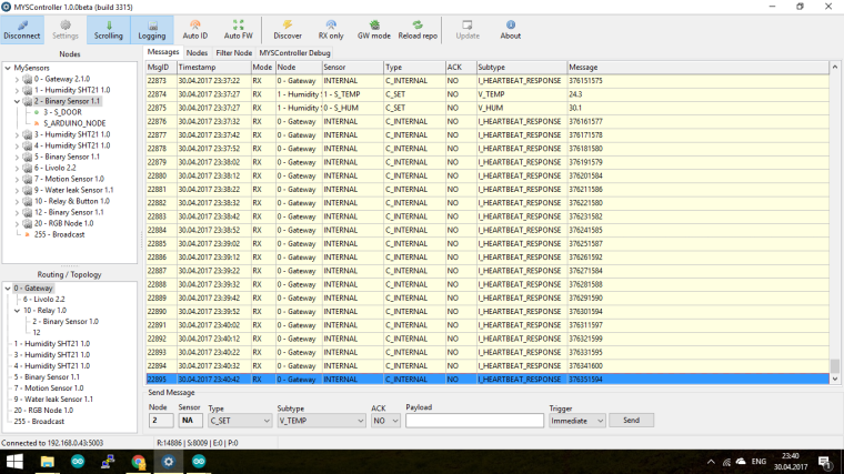
      Here is the serial output of the node when the repeater node 10 is on:

      0 MCO:BGN:INIT NODE,CP=RNNNA--,VER=2.1.0-beta
      4 TSM:INIT
      4 TSF:WUR:MS=0
      12 TSM:INIT:TSP OK
      14 TSF:SID:OK,ID=2
      16 TSM:FPAR
      53 TSF:MSG:SEND,2-2-255-255,s=255,c=3,t=7,pt=0,l=0,sg=0,ft=0,st=OK:
      1507 TSF:MSG:READ,10-10-2,s=255,c=3,t=8,pt=1,l=1,sg=0:1
      1513 TSF:MSG:FPAR OK,ID=10,D=2
      2060 TSM:FPAR:OK
      2060 TSM:ID
      2062 TSM:ID:OK
      2064 TSM:UPL
      2068 TSF:MSG:SEND,2-2-10-0,s=255,c=3,t=24,pt=1,l=1,sg=0,ft=0,st=OK:1
      2125 TSF:MSG:READ,0-10-2,s=255,c=3,t=25,pt=1,l=1,sg=0:2
      2131 TSF:MSG:PONG RECV,HP=2
      2136 TSM:UPL:OK
      2136 TSM:READY:ID=2,PAR=10,DIS=2
      2142 TSF:MSG:SEND,2-2-10-0,s=255,c=3,t=15,pt=6,l=2,sg=0,ft=0,st=OK:0100
      2191 TSF:MSG:READ,0-10-2,s=255,c=3,t=15,pt=6,l=2,sg=0:0100
      2199 TSF:MSG:SEND,2-2-10-0,s=255,c=0,t=17,pt=0,l=10,sg=0,ft=0,st=OK:2.1.0-beta
      2209 TSF:MSG:SEND,2-2-10-0,s=255,c=3,t=6,pt=1,l=1,sg=0,ft=0,st=OK:10
      2342 TSF:MSG:READ,0-10-2,s=255,c=3,t=6,pt=0,l=1,sg=0:M
      2351 TSF:MSG:SEND,2-2-10-0,s=255,c=3,t=11,pt=0,l=13,sg=0,ft=0,st=OK:Binary Sensor
      2361 TSF:MSG:SEND,2-2-10-0,s=255,c=3,t=12,pt=0,l=3,sg=0,ft=0,st=OK:1.1
      2371 TSF:MSG:SEND,2-2-10-0,s=3,c=0,t=0,pt=0,l=0,sg=0,ft=0,st=OK:
      2377 MCO:REG:REQ
      2396 TSF:MSG:SEND,2-2-10-0,s=255,c=3,t=26,pt=1,l=1,sg=0,ft=0,st=OK:2
      2500 TSF:MSG:READ,0-10-2,s=255,c=3,t=27,pt=1,l=1,sg=0:1
      2506 MCO:PIM:NODE REG=1
      2508 MCO:BGN:STP
      2510 MCO:BGN:INIT OK,TSP=1
      2514 MCO:SLP:MS=5,SMS=0,I1=255,M1=255,I2=255,M2=255
      2519 MCO:SLP:TPD
      2521 MCO:SLP:WUP=-1
      2525 TSF:MSG:SEND,2-2-10-0,s=3,c=1,t=16,pt=1,l=1,sg=0,ft=0,st=OK:1
      2533 MCO:SLP:MS=5,SMS=0,I1=255,M1=255,I2=255,M2=255
      2539 MCO:SLP:TPD
      2539 MCO:SLP:WUP=-1
      2545 TSF:MSG:SEND,2-2-10-0,s=255,c=3,t=0,pt=1,l=1,sg=0,ft=0,st=OK:100
      2553 MCO:SLP:MS=0,SMS=0,I1=1,M1=1,I2=255,M2=255
      2557 MCO:SLP:TPD
      2560 MCO:SLP:WUP=1
      2562 MCO:SLP:MS=5,SMS=0,I1=255,M1=255,I2=255,M2=255
      2568 MCO:SLP:TPD
      2570 MCO:SLP:WUP=-1
      2572 MCO:SLP:MS=5,SMS=0,I1=255,M1=255,I2=255,M2=255
      2578 MCO:SLP:TPD
      2578 MCO:SLP:WUP=-1
      2582 MCO:SLP:MS=0,SMS=0,I1=1,M1=1,I2=255,M2=255
      2586 MCO:SLP:TPD```
      posted in Troubleshooting
      Tigroenot
      Tigroenot
    • Node doesn't work without repeater

      Hello everybody!

      Please, I need an inspiration!
      I've got several nodes around my appartment: three temp/humidity sensors, double relay, door.
      I have built another relay node to hack my ikea floor lamp. It's working fine, and it has a default repeater feature. Now I have built another door sensor. It is a MySensors Stable node with MYS 1.3 bootloader. It's working through the node 10 (floor lamp). When I turn the lamp off to get rid of the repeater node the new door sensor (node 2) stops working. If I reboot it manually it doesn't find parent (I want it to be the gateway). I tried to assign manual parent ID 0 but it doesn't help.
      How do I make it work without the repeater? I want it to work in another room.

      P.S. I tried to clear eeprom, then flash the firmware, assign parent ID manually, rebooting it without repeater turned on, rebooted it near another repeater (double relay). Oh, I forgot to tell, the gateway is closer to the node then the repeater node 10.

      posted in Troubleshooting
      Tigroenot
      Tigroenot
    • RE: !TSM:FPAR:FAIL node and gateway communication problems?

      I experience a very strange behavior of couple of sensors. They don't find parent if no repeater nodes are present. As soon as I power on a repeater node they work fine. Why don't they get gateway as parent node? I tried to manually assign parent but no luck. I also tried to change their parent id through the myscontroller. They don't obey 🙂
      What did I miss?

      posted in Troubleshooting
      Tigroenot
      Tigroenot
    • RE: 💬 Building a Raspberry Pi Gateway

      @Flor-Sanders I think you maybe should choose not USB but Ethernet gateway in domoticz.

      posted in Announcements
      Tigroenot
      Tigroenot
    • RE: 💬 MySensors Stable Node

      Allright, I have replaced the nrf chips to those with + and... that was it, everything is working very well now 🙂
      Here they are, freshly handmade 🙂
      0_1482501760704_IMG_20161223_58958.jpg

      posted in OpenHardware.io
      Tigroenot
      Tigroenot
    • RE: livolo Glass Panel Touch Light Wall Switch + arduino 433Mhz

      @Nca78
      Well, now it's working fine for almost two weeks, no issues. I'm always trying to modify the sketch to work even better but it ends up that "the best is an enemy of the good" 🙂

      As for connections: as you can see on the photo of upper board I have connected 5 wires (actually later I added sixth). They are ground, two wires to leds for reading status (through 4k7 to pin 5 and 6), and wires to touch sensor pads (through optocoupler to pins 3 and 4, the other side of coupler to ground through 5nF cap) . I showed schematics earlier. With the sixth wire I took 3v from the drilled holes at the bottom of the board, as I remember the central hole. You can make sure with the multimeter.

      posted in My Project
      Tigroenot
      Tigroenot
    • RE: livolo Glass Panel Touch Light Wall Switch + arduino 433Mhz

      0_1482390326320_IMG_20161222_30763.jpg 0_1482390399345_IMG_20161222_2453.jpg
      0_1482392829327_IMG_20161222_30300.jpg

      posted in My Project
      Tigroenot
      Tigroenot
    • RE: livolo Glass Panel Touch Light Wall Switch + arduino 433Mhz

      And yes, I have a 47uF cap for radio and 100uF aluminum electrolytic cap for power input on the mcu.

      posted in My Project
      Tigroenot
      Tigroenot
    • RE: livolo Glass Panel Touch Light Wall Switch + arduino 433Mhz

      It's not just that. In the off state the switch is powered through a standby power circuit. When radio activates it draws power and the same moment the pic of the switch draws power, and the rele changes state to on also drawing a lot of power. All together it is a significant amount of power. So the voltage drops from 3v to 2,7-2,6 causing the brown out.
      And the 250mA is in theory. With the trans used.

      posted in My Project
      Tigroenot
      Tigroenot
    • RE: livolo Glass Panel Touch Light Wall Switch + arduino 433Mhz

      I have the pictures, but I have to resize them so the forum engine accepts. I will do it at work tomorrow.
      In two words you need to bypass the big resistor that feeds the transformator and decrease the resistance of the voltage divider that controls the mosfet in the primary coil of the trans. I'll provide the pictures.
      Can you please show the lower board of the 2016 model switch?

      P. S. And by the way I didn't find a proper way to control the esp switch in domoticz. I need to have two dummy switches - one for state and one for changing state. I used espEasy and Lua scripts both but no luck... With MySensors it is IMHO the proper way 🙂

      posted in My Project
      Tigroenot
      Tigroenot
    • RE: livolo Glass Panel Touch Light Wall Switch + arduino 433Mhz

      Those guys have an additional 12 v power wire in the switch mounting, the wire fore 12v power has been put there during the construction.
      The power supply in livolo switches is capable to make up to 250mA current. So I suppose it is not possible to feed the esp8266, but more than enough to power the 328p and Nrf24 radio. Currently I have one double button livolo switch running for a week or so with no issues whatsoever. But you have to change the BOD fuses to 1,8 v. Running at 2,7 bod causes reboot at sending data.
      Drawing more power from livolo power supply is not hard, but your load has to be at least 40w light bulbs.

      posted in My Project
      Tigroenot
      Tigroenot
    • RE: MYSBootloader 1.3pre2 testing

      The radio is not wired, it's directly soldered as a chip. I use MySensors Stable Node by @Koresh, but the nrf chips I got from China are probably counterfeit or don't work at all 🙂

      posted in Development
      Tigroenot
      Tigroenot
    • RE: 💬 MySensors Stable Node

      @Koresh Did that. No luck.

      0 MCO:BGN:INIT NODE,CP=RNNNA--,VER=2.1.0-beta
      4 TSM:INIT
      4 TSF:WUR:MS=0
      12 !TSM:INIT:TSP FAIL
      14 TSM:FAIL:CNT=1
      16 TSM:FAIL:PDT

      posted in OpenHardware.io
      Tigroenot
      Tigroenot
    • RE: MYSBootloader 1.3pre2 testing

      Please help to debug:
      0 MCO:BGN:INIT NODE,CP=RNNNA--,VER=2.1.0-beta
      4 TSM:INIT
      4 TSF:WUR:MS=0
      12 !TSM:INIT:TSP FAIL
      14 TSM:FAIL:CNT=1
      16 TSM:FAIL:PDT

      posted in Development
      Tigroenot
      Tigroenot
    • RE: 💬 MySensors Stable Node

      I checked everything twice of course. I don't have 0402 1M resistor, the smallest I have is 0805 🙂

      posted in OpenHardware.io
      Tigroenot
      Tigroenot
    • RE: 💬 MySensors Stable Node

      Hi,
      I aasembled your node, but the radio chip version is not the + one. After burning the MYS bootloader is prints the debug in serial:
      60110 TSM:FAIL:RE-INIT
      60112 TSM:INIT
      60119 !TSM:INIT:TSP FAIL
      60123 TSM:FAIL:CNT=7
      60125 TSM:FAIL:PDT

      Any suggestions?

      posted in OpenHardware.io
      Tigroenot
      Tigroenot
    • RE: livolo Glass Panel Touch Light Wall Switch + arduino 433Mhz

      0_1481683810069_07d5c9.jpg

      The upper part is connection to touch sensor, the lower to status (red LED).

      posted in My Project
      Tigroenot
      Tigroenot
    • RE: livolo Glass Panel Touch Light Wall Switch + arduino 433Mhz

      @frankie This diagram shows how a guy fixed his switch that didn't change the rele. But it is quite right. You need to add an optocoupler to connect to the sensor pin with 5,1 pF con to ground and connect the LED to the arduino sensor pin through resistor for the status read. I'll try to find the diagram later.

      posted in My Project
      Tigroenot
      Tigroenot
    • RE: livolo Glass Panel Touch Light Wall Switch + arduino 433Mhz

      @Nca78 The euro version doesn't. Just the ULN2003A.
      Unfortunately, I can't attach images for some unknown reason.

      0_1481625608930_IMG_20161213_203852.jpg

      Finally 🙂
      That's a single button switch.

      posted in My Project
      Tigroenot
      Tigroenot
    • RE: livolo Glass Panel Touch Light Wall Switch + arduino 433Mhz

      Well, somehow I got over it 🙂

      Here is a working sketch for livolo two button switch:

      /**
       * The MySensors Arduino library handles the wireless radio link and protocol
       * between your home built sensors/actuators and HA controller of choice.
       * The sensors forms a self healing radio network with optional repeaters. Each
       * repeater and gateway builds a routing tables in EEPROM which keeps track of the
       * network topology allowing messages to be routed to nodes.
       *
       * Created by Henrik Ekblad <henrik.ekblad@mysensors.org>
       * Copyright (C) 2013-2015 Sensnology AB
       * Full contributor list: https://github.com/mysensors/Arduino/graphs/contributors
       *
       * Documentation: http://www.mysensors.org
       * Support Forum: http://forum.mysensors.org
       *
       * This program is free software; you can redistribute it and/or
       * modify it under the terms of the GNU General Public License
       * version 2 as published by the Free Software Foundation.
       *
       *******************************
      */
      
      
      #define MY_RADIO_NRF24
      #define MY_REPEATER_FEATURE
      #include <MySensors.h>
      
      #define sensor1_PIN 5  //Pin to attach the indicator LED1
      #define sensor2_PIN 6   // LED2
      #define RELAY1_PIN 3  // Arduino Digital I/O pin number for relay 
      #define RELAY2_PIN 4 
      #define CHILD_ID_LIGHT1 1   // Id of the sensor child
      #define CHILD_ID_LIGHT2 2
      #define RELAY_ON 1
      #define RELAY_OFF 0
       
      int oldValue1=0;
      bool state1;
      int oldValue2=0;
      bool state2;
      
      MyMessage msg(CHILD_ID_LIGHT1,V_LIGHT);
      MyMessage msg2(CHILD_ID_LIGHT2,V_LIGHT);
      
      void setup()  
      {  
        delay(2400);
         pinMode(sensor1_PIN,INPUT);
         pinMode(sensor2_PIN,INPUT);
         digitalWrite(RELAY1_PIN, RELAY_OFF); // Make sure relays are off when starting up
         digitalWrite(RELAY2_PIN, RELAY_OFF); // Make sure relays are off when starting up
         pinMode(RELAY1_PIN, OUTPUT);         // Then set relay pins in output mode
         pinMode(RELAY2_PIN, OUTPUT);         // Then set relay pins in output mode
         state1=false;
      state2=false;
      }
       
      void presentation()  
      { 
        // Register all sensors to gw (they will be created as child devices)
        sendSketchInfo("Livolo", "2.0");
        present(CHILD_ID_LIGHT1, S_LIGHT);
        present(CHILD_ID_LIGHT2, S_LIGHT);
        delay(1400);
      }
      
      void loop() 
      {
      
       int value1 = digitalRead(sensor1_PIN);
          if (value1==1){
            state1=true;
          }else{
            state1=false;
          }
      
        if (value1 != oldValue1) {
            send(msg.set(state1), true); // Send new state and request ack back
        }
        oldValue1 = value1;
      
        int value2 = digitalRead(sensor2_PIN);
        if (value2==1){
            state2=true;
          }else{
            state2=false;
          }
        if (value2 != oldValue2) {
            send(msg2.set(state2), true); // Send new state and request ack back
        }
        oldValue2 = value2;
      } 
       
      void receive(const MyMessage &message) {
      
        if (message.type == V_LIGHT) {
           // Change relay state
      switch (message.sensor) {
            case 1:
              state1=message.getBool();
              digitalWrite(message.sensor+2, RELAY_ON);
              delay(30);
              digitalWrite(message.sensor+2, RELAY_OFF);  
              delay(30); 
              break;
            case 2:
              state2 = message.getBool();
              digitalWrite(message.sensor+2, RELAY_ON);
              delay(30);
              digitalWrite(message.sensor+2, RELAY_OFF);  
              delay(30);     
              break;
            }
         }
      }
      
      posted in My Project
      Tigroenot
      Tigroenot
    • RE: livolo Glass Panel Touch Light Wall Switch + arduino 433Mhz

      There really is an opportunity to draw enough power from livolo internal circuits for atmega328 and a radio. With the great help of @DJONvl I managed to power up an arduino with nrf24 radio directly from the switch.
      But...
      I have a two button switch, and i tried to adopt the above scetch for my purpose (and the development version of the library) but got stuck... Can anyone please have a glance at my scetch and push me towards the right way? 🙂

      /**
       * The MySensors Arduino library handles the wireless radio link and protocol
       * between your home built sensors/actuators and HA controller of choice.
       * The sensors forms a self healing radio network with optional repeaters. Each
       * repeater and gateway builds a routing tables in EEPROM which keeps track of the
       * network topology allowing messages to be routed to nodes.
       *
       * Created by Henrik Ekblad <henrik.ekblad@mysensors.org>
       * Copyright (C) 2013-2015 Sensnology AB
       * Full contributor list: https://github.com/mysensors/Arduino/graphs/contributors
       *
       * Documentation: http://www.mysensors.org
       * Support Forum: http://forum.mysensors.org
       *
       * This program is free software; you can redistribute it and/or
       * modify it under the terms of the GNU General Public License
       * version 2 as published by the Free Software Foundation.
       *
       *******************************
      */
      
      
      #define MY_RADIO_NRF24
      #define MY_REPEATER_FEATURE
      #include <MySensors.h>
      
      #define sensor1_PIN 5
      #define sensor2_PIN 6
      #define RELAY1_PIN 3  // Arduino Digital I/O pin number for relay 
      #define RELAY2_PIN 4 
      #define CHILD_ID_LIGHT1 1   // Id of the sensor child
      #define CHILD_ID_LIGHT2 2
      #define RELAY_ON 1
      #define RELAY_OFF 0
       
      int oldValue1=0;
      bool state1;
      bool sens1;
      int oldValue2=0;
      bool state2;
      bool sens2;
      
      //MySensor gw;
      MyMessage msg(CHILD_ID_LIGHT1,V_LIGHT);
      MyMessage msg2(CHILD_ID_LIGHT2,V_LIGHT);
      
      void setup()  
      {  
        delay(2400);
         pinMode(sensor1_PIN,INPUT);
         pinMode(sensor2_PIN,INPUT);
         digitalWrite(RELAY1_PIN, RELAY_OFF); // Make sure relays are off when starting up
         digitalWrite(RELAY2_PIN, RELAY_OFF); // Make sure relays are off when starting up
         pinMode(RELAY1_PIN, OUTPUT);         // Then set relay pins in output mode
         pinMode(RELAY2_PIN, OUTPUT);         // Then set relay pins in output mode
         state1=false;
         state2=false;
      }
       
      void presentation()  
      { 
        // Register all sensors to gw (they will be created as child devices)
        sendSketchInfo("Livolo", "1.2");
        present(CHILD_ID_LIGHT1, S_LIGHT);
        present(CHILD_ID_LIGHT2, S_LIGHT);
        delay(1400);
      }
      
      void loop() 
      {
      
       int value1 = digitalRead(sensor1_PIN);
          if (value1==1){
            state1=true;
          }else{
            state1=false;
          }
      
        if (value1 != oldValue1) {
            send(msg.set(state1), true); // Send new state and request ack back
        }
        oldValue1 = value1;
      
        int value2 = digitalRead(sensor2_PIN);
        if (value2==1){
            state2=true;
          }else{
            state2=false;
          }
      
        if (value2 != oldValue2) {
            send(msg2.set(state2), true); // Send new state and request ack back
        }
        oldValue2 = value2;
      } 
       
      void receive(const MyMessage &message) {
      
        if (message.type == V_LIGHT) {
           // Change relay state
          bool instate = message.getBool();
      
       while(instate!=state1){
           digitalWrite(message.sensor, RELAY_ON); 
           delay(30);
           digitalWrite(message.sensor, RELAY_OFF);  
           delay(30);     
          int value1 =digitalRead(sensor1_PIN);
          if (value1==1){
            state1=true;
          }else{
            state1=false;
          }
          int value2 =digitalRead(sensor2_PIN);
          if (value2==1){
            state2=true;
          }else{
            state2=false;
          }
       }    
          
      
         } 
      }


      The problem is in the receive()
      I need to destinguish the incoming state for each sensor child and set the instate value accordigly.

      Please, help, I didn't sleep for so long 🙂

      posted in My Project
      Tigroenot
      Tigroenot
    • RE: MYSBootloader 1.3pre2 testing

      Tried this bootloader.
      Have two nodes 8MHz internal, two nodes 1MHz. All run beautifully, the OTA firmware update around a minute with binaryButton sketch. But the node startup is around 7-8 seconds. And no problems uploading the sketch via serial.
      I use an UNO as an ASP to burn the bootloader and a simple USB_TTL FTDI converter to upload sketches.

      posted in Development
      Tigroenot
      Tigroenot
    • RE: Fire pit RGB striplight controller

      @Boots33
      Looks awesome!
      I have a question. I took your sketch and it works great, but is it possible not to use the separate V_LIGHT to turn it on/off? What I mean is that I don't want to put a rele or a MOSFET to control the RGB power but to start/stop dimming by using just one RGB icon in domoticz. And turn it off by either setting dimmer value to 0 or pressing the off button in domoticz RGB switch. Is it possible?

      posted in My Project
      Tigroenot
      Tigroenot
    • RE: [Solved] Does not work after latest update

      Reporting: I have thrown away the capacitors that I've bought from Ali and replaced them by those bougth here localy (47uF) and everything worked like a charm! So to admit, the promblem IS indeed in the decoupling capacitors! Very happy guy here! 🙂

      posted in Troubleshooting
      Tigroenot
      Tigroenot
    • RE: [Solved] Does not work after latest update

      @Jic I sure did, to erase the node id value.

      posted in Troubleshooting
      Tigroenot
      Tigroenot
    • RE: 💬 Building a Raspberry Pi Gateway

      @RogerB68 I had the same situation. I have removed the mtune parameter from the config file and compilation went fine. I don't know what it affects though. 🙂

      posted in Announcements
      Tigroenot
      Tigroenot
    • RE: [Solved] Does not work after latest update

      I will try to move my gateway from raspberry to esp. When I compiled gateway on raspberry it has argued on some parameter in config, I removed the cortex a7 entry and all went fine. Maybe it was the issue.

      posted in Troubleshooting
      Tigroenot
      Tigroenot
    • RE: [Solved] Does not work after latest update

      @Jic I have all Nrf24 modules soldered, with caps (tried 20 and 47 uF), I have three versions of Nrf24 modules: from the mysensors shop, smd and plna. On the gateway I have plna, on sensors I have both the others. Those sensors worked fine for almost a year, and stoped after I have updated them to 2.0.0 or development branch. On the gateway side I have latest development version.
      Maybe all my radio modules are clones that do not work with the versions of mysensors higher than 1.4?

      And I use domoticz. Maybe I should switch to openhub?

      posted in Troubleshooting
      Tigroenot
      Tigroenot
    • RE: [Solved] Does not work after latest update

      Hello everybody!
      This my first post, but I've been reading for a long while and realy admire the team for the work done 🙂

      I have moved to development branch, I have latest MySensors on my gateway (Rpi2 + nrf24l01+plna, caps and reg to solve the power issue), burned the MYSBootloader (8MHz internal) and could upload the binary scetch via serial.
      Now i have that problem with !TSM:FPAR:NO REPLY on the node side.
      I can see the FPAR request on the gateway side.

      653051 TSM:INIT
      653060 TSM:INIT:TSP OK
      653062 TSM:FPAR
      653064 TSF:MSG:SEND,255-255-255-255,s=255,c=3,t=7,pt=0,l=0,sg=0,ft=0,st=OK:
      655073 !TSM:FPAR:NO REPLY
      655075 TSM:FPAR
      655077 TSF:MSG:SEND,255-255-255-255,s=255,c=3,t=7,pt=0,l=0,sg=0,ft=0,st=OK:
      657088 !TSM:FPAR:NO REPLY
      657090 TSM:FPAR
      657092 TSF:MSG:SEND,255-255-255-255,s=255,c=3,t=7,pt=0,l=0,sg=0,ft=0,st=OK:
      659103 !TSM:FPAR:NO REPLY
      659105 TSM:FPAR
      659107 TSF:MSG:SEND,255-255-255-255,s=255,c=3,t=7,pt=0,l=0,sg=0,ft=0,st=OK:
      661121 !TSM:FPAR:FAIL
      661123 TSM:FAIL:CNT=7
      661125 TSM:FAIL:PDT```
      
      
      mysgw: TSF:MSG:READ,255-255-255,s=255,c=3,t=7,pt=0,l=0,sg=0:
      mysgw: TSF:MSG:BC
      mysgw: TSF:MSG:FPAR REQ,ID=255
      mysgw: TSF:PNG:SEND,TO=0
      mysgw: TSF:CKU:OK
      mysgw: TSF:MSG:GWL OK
      mysgw: TSF:MSG:SEND,0-0-255-255,s=255,c=3,t=8,pt=1,l=1,sg=0,ft=0,st=OK:0
      mysgw: Client 0: 0;0;3;0;18;PING
      mysgw: TSF:MSG:READ,255-255-255,s=255,c=3,t=7,pt=0,l=0,sg=0:
      mysgw: TSF:MSG:BC
      mysgw: TSF:MSG:FPAR REQ,ID=255
      mysgw: TSF:CKU:OK,FCTRL
      mysgw: TSF:MSG:GWL OK
      mysgw: TSF:MSG:SEND,0-0-255-255,s=255,c=3,t=8,pt=1,l=1,sg=0,ft=0,st=OK:0
      mysgw: TSF:MSG:READ,255-255-255,s=255,c=3,t=7,pt=0,l=0,sg=0:
      mysgw: TSF:MSG:BC
      mysgw: TSF:MSG:FPAR REQ,ID=255
      mysgw: TSF:CKU:OK,FCTRL
      mysgw: TSF:MSG:GWL OK
      mysgw: TSF:MSG:SEND,0-0-255-255,s=255,c=3,t=8,pt=1,l=1,sg=0,ft=0,st=OK:0
      mysgw: TSF:MSG:READ,255-255-255,s=255,c=3,t=7,pt=0,l=0,sg=0:
      mysgw: TSF:MSG:BC
      mysgw: TSF:MSG:FPAR REQ,ID=255
      mysgw: TSF:CKU:OK,FCTRL
      mysgw: TSF:MSG:GWL OK
      mysgw: TSF:MSG:SEND,0-0-255-255,s=255,c=3,t=8,pt=1,l=1,sg=0,ft=0,st=OK:0
      

      Though there is no sign of activity in MYSController (the one included with the MYSBootloader archive)

      I have tried differen radio modules, different pro minis, modules not jumper wired but soldered with short wires and caps (10, 20, 47 uF). The other 3 nodes are responding (2 x si7021 + motion sensor) but they are on 1.5 version I suppose.

      EDIT: The interestinf thing is that I tried to update my perfectly working motion sensor and it doesn't work now.

      TSM:FPAR
      TSP:MSG:SEND 1-1-255-255 s=255,c=3,t=7,pt=0,l=0,sg=0,ft=0,st=bc:
      !TSM:FPAR:FAIL
      !TSM:FAILURE```
      posted in Troubleshooting
      Tigroenot
      Tigroenot