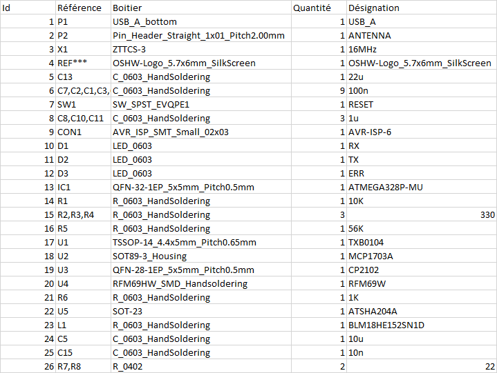
Hi all,
As you requested, if someone want to check the board, i have adapted it for LINOVO 2 gangs 1 way EU format.
You can find the files her https://github.com/tonnerre33/Linovo_EU_2Gang_1way/tree/develop/ ;)
Hi all,
As you requested, if someone want to check the board, i have adapted it for LINOVO 2 gangs 1 way EU format.
You can find the files her https://github.com/tonnerre33/Linovo_EU_2Gang_1way/tree/develop/ ;)
Hi,
Did you check the SOFT_HMAC_KEY in your gateway with the skecth SecurityPersonalizer.ino ?
He must be the same at the HMAC node.
Hi,
I desoldered it for increase the battery life ;) I did the same for the regulator.
You can find more informations here : https://www.mysensors.org/build/battery
Thx for your interest :)
I have just posted the pictures of the v1.1 version. Have fun.

A fast extraction without traitment if that can help ;)
Ok try to remove the jumper between V+ and AREF
@scalz Ok, so i will connect the ant pin and change the config :+1:
Thank you for your help Scalz ;)
It's ok, i haven't seen the fuse in the primary of the hilink ;)
with this fuse, the protection is guaranteed, then you don't need termofuse in this project :+1:
thanx for answer how you made your choice and i hope the release will arrive soon :)
Hello,
It seems to me that this function is only in the developed branch with the parameter
MY_TRANSPORT_WAIT_READY_MS
More information at https://github.com/mysensors/MySensors/search?utf8=✓&q=MY_TRANSPORT_WAIT_READY_MS&type=Code
@tlustoch You need to enable MY_OTA_FIRMWARE_FEATURE only if you use DualOptiBoot.
With MYSBootloader, you don't need ;)
I use MYSBootloader 1.3 pre-release with mysensors 2.0. You can find it here : https://forum.mysensors.org/topic/3453/mysbootloader-1-3-pre-release-myscontroller-1-0-0beta
And yes it usable with 8 MHZ internal clock config if you burn the bootloader with 8Mhz internal clock setting.
I think it's DipTrace ;)
@mar.conte said in Sleep dont run:
Hi, you need to change the SLEEP_TIME value .
For example :
SLEEP_TIME = 10000 //Time in milliseconds
@giovaFr said in 💬 Battery Powered Sensors:
A0maxV = VbattMax * (R1 / (R1+R2)
Are you sure about that ? I think is A0maxV = VbattMax * (R2 / (R1+R2)
R2 = 150k Ohms for 8.4V with R1 always at 1M Ohms
Hello
Will you build an nrf24l01 smd version ?
@gohan said in 💬 Battery Powered Sensors:
Hello, i didn't know why you add 4 measures (batarray) and you divide by 3 the sum .
Thanks you ;)
But i don't understand the difference between your 3 boost projects :( can you explain to me ? :)
@scalz Oki. And for the nrf24 version ? :)
@Justas Hello,
yes you have to buy parts and assemble them yourself. 1.5$ by PCB is cheap, you can't have the components for this price ;)
@HouseIOT said in 💬 4-channel switcher/dimmer:
It is just my first project and it has some weaknesses
It's a very good project for your first. I hope see many another projects from you ;)
@mtiutiu Thanks you for your anwser ;)
Did you test a two way switch (va et viens) ?
I think we can do this with 1 gang 2 way :
https://fr.aliexpress.com/item/Black-Crystal-Glass-Switch-Livolo-EU-Standard-VL-C701SR-12-1-Gang-2-Way-Remote-Control/32786281129.html
Awesome work dude !! And you did the pcb on eagle, you are my hero <3
That's will help me for develop EU version ;)
Thx a lot