yes , but this solution needs buying of sensor which costs about 25-30 € , this what I write , take a look on it needs only resistors and wires (plus arduino and radio of course)
warmaniac
@warmaniac
Posts
-
Lightning report - any idea ? -
Lightning report - any idea ?Yes this is true but these requires of buying sensors for about 30€ for example AS3935 , I think that one , which I mentioned is cheap because it only needs 2x 10 kOhm and 3,3 mOhm resistors . Only problem which I had is bring that code works with mysensors.
-
Lightning report - any idea ?Hi ,
I found this simple setup for lightning detection
[https://create.arduino.cc/projecthub/runtimeprojects/a-lightning-detector-for-arduino-9f679c](link url)
is there some way to implement it with mysensors to see it for example in domoticz ?
-
💬 Sonoff relay using MySensors ESP8266 wifi or mqtt gateway@gohan said in 💬 Sonoff relay using MySensors ESP8266 wifi or mqtt gateway:
is it reachable via IP or is it totally unresponsive?
I had same problem too.. When is longer not turned on, Sonoff disconnects from wifi , that ip is not in client list, in my case I only turn sonoff on throught black button on the top and than it is okay about day-two.
-
💬 Sonoff relay using MySensors ESP8266 wifi or mqtt gatewayAfter electricity plugged off , it stops working / not connecting to wifi router, but on manual click it turns on and of , it is problem because I don't use haas config ? I dont know where can I place them, can you help me ? :) thanks
-
LED strip remote without relay?And what about 433 mhz way like RFlink as usb gateway ? Will it drain less ?
-
LED strip remote without relay?Thanks for reply and interest, but question is : Do I need use Solid state relay or classic relay or how can I switch light on/off ? Thanks
-
LED strip remote without relay?Hi ,
I want to help make led strip remote powered trought 3x AAA batteries , which can I turn on/off remotely without relay (it consumes lot of power). I think when it works on 5V battery(3xAA) it may be powered trought arduino , or any ideas ?
Led strip here
-
💬 Sonoff relay using MySensors ESP8266 wifi or mqtt gatewayTried LAN sketch after adding new hardware in domoticz this error occurs
2017-04-06 06:28:07.230 MQTT: Connecting to 192.168.2.209:5003
2017-04-06 06:28:07.335 Error: MQTT: disconnected, restarting (rc=2)
after that Sonoff blik twice. What may be wrong ?
Edit:
Understand now , it is added as classic mysensor LAN gateway , now working fine ! I tried to do it complicated way , but it was easy :D
2017-04-06 06:30:29.756 MySensors: trying to connect to: 192.168.2.209:5003
2017-04-06 06:30:30.757 MySensors: connected to: 192.168.2.209:5003
2017-04-06 06:30:30.758 MySensors: Gateway Ready...
2017-04-06 06:30:30.762 MySensors: Node: 0, Sketch Name: Sonoff ethernet
2017-04-06 06:30:30.763 MySensors: Node: 0, Sketch Version: 1.0
2017-04-06 06:30:30.769 (MQTT) Light/Switch (Light)
2017-04-06 06:30:31.778 MySensors: Gateway Version: 2.1.1
2017-04-06 06:30:31.779 MySensors: Gateway Version: 2.1.1
2017-04-06 06:31:11.939 User: Admin initiated a switch command (87/Sonoff-1/On) 2017-04-06 06:31:11.942 (MQTT) Light/Switch (Sonoff-1) 2017-04-06 06:31:12.789 (MQTT) Light/Switch (Sonoff-1) -
💬 Sonoff relay using MySensors ESP8266 wifi or mqtt gateway@Efflon said in 💬 Sonoff relay using MySensors ESP8266 wifi or mqtt gateway:
@warmaniac the sonoff works just like any sensor except its configured as a gateway since that is what is needed for esp8266+mysensors . Mqtt or ethernet/wifi is just a matter of taste and your setup, skip mqtt if you don't have anything else using it.
I want to use standalone Sonoff (one device) than I must install broker (Mosquito) on my raspberry where is Domoticz running ? And how can I add than that device or how can this setup looks like.
-
💬 Sonoff relay using MySensors ESP8266 wifi or mqtt gatewayCan I ask please ? I don't know if I understand correctly principle of working Sonoff under mysensors , I uploaded sketch from here to Sonoff , Sonoff is connected to my WiFi network , now I need to make MQTT gateway connected trought LAN or WiFi to the raspberry where is running Domoticz ? I had nodeMCU will it work ? Thanks much
-
SCT-013-030 current monitor sensorupdated my sketch with new values for SCT-013-00 result is now
#define MY_DEBUG
#define MY_RADIO_NRF24
// EmonLibrary examples openenergymonitor.org, Licence GNU GPL V3  ***/
#include <SPI.h>
#include <MySensors.h>
#include "EmonLib.h"             // Include Emon Library
EnergyMonitor emon1;             // Create an instance

#define CHILD_ID_CLAMP1 0
#define PIN_ANALOG_I1 A1 //pince amperemetrique1

unsigned long lastSend_power = millis();
unsigned long lastSend_c = millis();
unsigned long SEND_FREQUENCY = 120000; // Minimum time between send (in milliseconds). We don't wnat to spam the gateway.
unsigned long SEND_FREQUENCY_C = SEND_FREQUENCY / 30;
int index = 0;
double Irms1 = 0;
boolean pcReceived1 = false;
float nrj1 = 0, old_nrj1;

MyMessage IrmsMsg1(CHILD_ID_CLAMP1, V_WATT);
MyMessage kWhMsg1(CHILD_ID_CLAMP1, V_KWH);
MyMessage pcMsg1(CHILD_ID_CLAMP1, V_VAR1);

void before() {

}


void presentation()
{
  sendSketchInfo("Multisensors_Entree", "2.0");  // Send the sketch version information to the gateway and Controller
  present(CHILD_ID_CLAMP1, S_POWER);   // Register this device as power sensor
  request(CHILD_ID_CLAMP1, V_VAR1);
}


void receive(const MyMessage &message)
{
  if (message.type == V_VAR1)
  {
    nrj1 = old_nrj1 = message.getFloat();
    Serial.print("Received last nrj count from gw:");
    Serial.println(nrj1);
    pcReceived1 = true;
  }
}

void setup()
{
  emon1.current(PIN_ANALOG_I1, 111.1);       // Current: input pin, calibration.
  Serial.println("SETUP completed");
}

void envoi_donnees(double intrms, int id_clamp)
{
  Serial.print("Envoi des donnees .... clamp="); Serial.println(id_clamp);
  double energie = (intrms * 240.0 * SEND_FREQUENCY / 1000) / 3.6E6;
  switch (id_clamp) //can be modified ...
  {
    case 1:
      {
        send(IrmsMsg1.set(intrms * 240.0, 1));
        nrj1 += energie;
        send(kWhMsg1.set(nrj1, 5));
        send(pcMsg1.set(nrj1, 5));
        old_nrj1 = nrj1;
      }
      break;
  }
}

void loop() {
  unsigned long now = millis();
  bool sendTime_c = now - lastSend_c > SEND_FREQUENCY_C;
  // Calcul de Irms1 et Irms2
  if (sendTime_c) //calcul Irms moy clamp1/clamp2
  {
    if (index == 0)
    {
      Irms1 = emon1.calcIrms(1480);
    }
    else
    {
      Irms1 = (index * Irms1 + emon1.calcIrms(1480)) / (index + 1);
    }
    lastSend_c = now;
    index++;
  }

bool sendTime_power = now - lastSend_power > SEND_FREQUENCY;

 if (sendTime_power)
{
  // Envoi ou request Puissance1
  if (pcReceived1) envoi_donnees(Irms1, 1);
  else     {
    request(CHILD_ID_CLAMP1, V_VAR1);
    Serial.println("Request VAR1");
  }
  //on reinitialise les compteurs
  lastSend_power = now;
  index = 0;
  }
}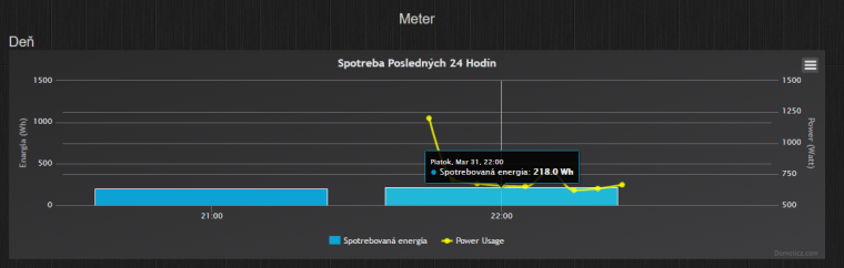
-
SCT-013-030 current monitor sensor -
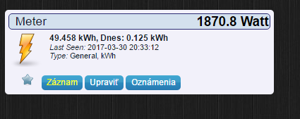
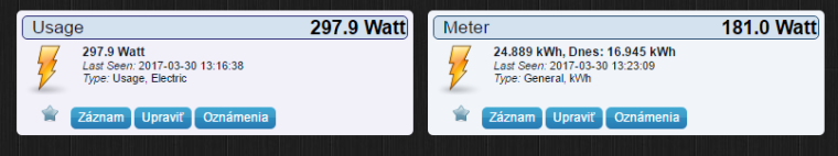
SCT-013-030 current monitor sensorBecause with test sketch from that site I get actual consumption 0,5 kWh but from mysensors sketch I get much higher values look
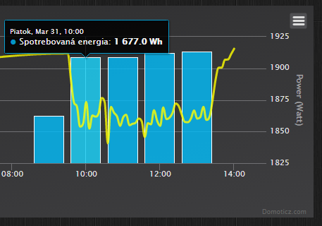
1,7 kWh per one hour is too much , I had only TV and fridge in power on mode, I had total consumption per last year about 2140 kWh , which is about 6 kWh per day.
-
SCT-013-030 current monitor sensorOkay :) understand now, and what about calibration for wiring I followig this site
And they calibrate
emon1.current(1, 111.1);And yours calibration
emon1.current(PIN_ANALOG_I1, 30.0);Is some difference after this calibrations in measuring ?
-
SCT-013-030 current monitor sensorThank you very much! Only one question left, with multimeter I measured my voltage 241.0 V could I update it in sketch or ?
-
SCT-013-030 current monitor sensor -
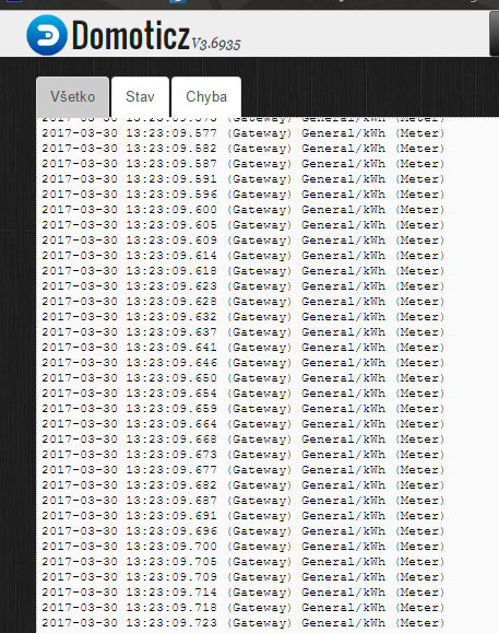
SCT-013-030 current monitor sensorI modyfied your sketch (deleting unwanted code like dallas and light sensor) it works but i think I done something wrong, because it spams my gateway , now it looks like this
//#include <Arduino.h>
#define MY_DEBUG
#define MY_RADIO_NRF24
// EmonLibrary examples openenergymonitor.org, Licence GNU GPL V3  ***/
#include <SPI.h>
#include <MySensors.h>
#include <OneWire.h>
#include "EmonLib.h"             // Include Emon Library
EnergyMonitor emon1;             // Create an instance

#define CHILD_ID_CLAMP1 0
#define PIN_ANALOG_I1 A1 //pince amperemetrique1

bool receivedConfig = false;
bool metric = true; //truc v2.0

//int compat = 0;
unsigned long lastSend_temp = millis();
unsigned long lastSend_power = millis();
unsigned long lastSend_c;
unsigned long SEND_FREQUENCY = 120000; // Minimum time between send (in milliseconds). We don't wnat to spam the gateway.
unsigned long SEND_FREQUENCY_C = SEND_FREQUENCY / 30;
int index = 0;
double Irms1 = 0;
boolean pcReceived1 = false;

float nrj1 = 0, old_nrj1;

MyMessage IrmsMsg1(CHILD_ID_CLAMP1, V_WATT);
MyMessage kWhMsg1(CHILD_ID_CLAMP1, V_KWH);
MyMessage pcMsg1(CHILD_ID_CLAMP1, V_VAR1);

void presentation()
{

  sendSketchInfo("Multisensors_Entree", "2.0");  // Send the sketch version information to the gateway and Controller
  present(CHILD_ID_CLAMP1, S_POWER);   // Register this device as power sensor
  request(CHILD_ID_CLAMP1, V_VAR1);
}


void receive(const MyMessage &message)
{
  if (message.type == V_VAR1)
  {
    nrj1 = old_nrj1 = message.getFloat();
    Serial.print("Received last nrj count from gw:");
    Serial.println(nrj1);
    pcReceived1 = true;
  }

}

void setup()
{
  emon1.current(PIN_ANALOG_I1, 30.0);       // Current: input pin, calibration.
  Serial.println("SETUP completed");
}

void envoi_donnees(double intrms, int id_clamp)
{
  Serial.print("Envoi des donnees .... clamp="); Serial.println(id_clamp);
  double energie = (intrms * 232.0 * SEND_FREQUENCY / 1000) / 3.6E6;
  switch (id_clamp)
  {
    case 1:
      {
        send(IrmsMsg1.set(intrms * 232.0, 1));
        nrj1 += energie;
        send(kWhMsg1.set(nrj1, 5));
        send(pcMsg1.set(nrj1, 5));
        old_nrj1 = nrj1;
      }
      break;
  }
}

void loop() {
  unsigned long now = millis();
  bool sendTime_c = now - lastSend_c > SEND_FREQUENCY_C;
  // Calcul de Irms1 et Irms2
  if (sendTime_c) //calcul Irms moy clamp1/clamp2
  {
    if (index == 0)
    {
      Irms1 = emon1.calcIrms(1480);
    }
    else
    {
      Irms1 = (index * Irms1 + emon1.calcIrms(1480)) / (index + 1);
    }
    lastSend_c = now;
    index++;
  }

bool sendTime_power = now - lastSend_power > SEND_FREQUENCY;

 if (sendTime_power)
{

  // Envoi ou request Puissance1
  if (pcReceived1) envoi_donnees(Irms1, 1);
  else     {
    request(CHILD_ID_CLAMP1, V_VAR1);
    Serial.println("Request VAR1");
  }

  }
}
and I get this results now
-
SCT-013-030 current monitor sensornice ! thank you very much for fast solution :) I try it at home , it compiles well :+1:
-
SCT-013-030 current monitor sensortried to modify but I always get error
/MySensors.h:328:2: error: #error No forward link or gateway feature activated. This means nowhere to send messages! Pretty pointless.
#error No forward link or gateway feature activated. This means nowhere to send messages! Pretty pointless.
// EmonLibrary examples openenergymonitor.org, Licence GNU GPL V3  ***/
#include <SPI.h>
#include <MySensors.h>
#include "EmonLib.h"             // Include Emon Library
EnergyMonitor emon1;             // Create an instance
#define CHILD_ID 0
#define MY_RADIO_NRF24
#define PIN_ANALOG_I A1

//MySensor gw;
unsigned long lastSend;
unsigned long lastSend2;
unsigned long SEND_FREQUENCY = 20000; // Minimum time between send (in milliseconds). We don't wnat to spam the gateway.
unsigned long SEND_FREQUENCY2 = SEND_FREQUENCY / 25;
int index = 0;
double Irms=0;
double power;
boolean pcReceived = false;
boolean onyva=true;
float nrj=0, old_nrj;
MyMessage IrmsMsg(CHILD_ID,V_WATT);
MyMessage kWhMsg(CHILD_ID,V_KWH);
MyMessage pcMsg(CHILD_ID,V_VAR1);


//void incomingMessage(const MyMessage &message)

void receive(const MyMessage &message)
{
  if (message.type==V_VAR1)
  {
    nrj = old_nrj = message.getFloat();
    Serial.print("Received last nrj count from gw:");
    Serial.println(nrj);
    pcReceived = true;
  }
}

void presentation () {

  sendSketchInfo("Energy Meter", "1.0");  // Send the sketch version information to the gateway and Controller
  present(CHILD_ID, S_POWER);   // Register this device as power sensor
  request(CHILD_ID, V_VAR1);

  }

void setup()
{
  begin(incomingMessage);
  emon1.current(PIN_ANALOG_I, 30.0);       // Current: input pin, calibration.
}

void loop()
{
  if (onyva) process();
  onyva = false;
  unsigned long now = millis();
  //unsigned long now2 = millis();
  bool sendTime2 = now - lastSend2 > SEND_FREQUENCY2;
  if (sendTime2) //calcul Irms moy
  {
    if (index==0) Irms=emon1.calcIrms(1480);
    else {
    index++;
    Irms = (index*Irms+emon1.calcIrms(1480))/(index+1);
    }
    lastSend2 = now;
  }
  bool sendTime = now - lastSend > SEND_FREQUENCY;
  if (sendTime && pcReceived)
  {
    power = Irms*232.0;
    send(IrmsMsg.set(power,1));
    Serial.println(Irms*232.0);
    nrj += (power*SEND_FREQUENCY/1000)/3.6E6;
    send(kWhMsg.set(nrj,5));
    send(pcMsg.set(nrj,5));
    lastSend = now;
    index = 0;
    old_nrj=nrj;
    onyva=true;
  }
 else if (sendTime && !pcReceived)
 {
  request(CHILD_ID, V_VAR1);
  lastSend=now;
  index=0;
  onyva=true;
 }
}
It is possible to compile it with old mysensors library ? It will work with gateway which has a newest version ?