@alexsh1 Sorry you missunderstood. My post was only a hint to help riro2 with his LORA problem. The Libraries from the refered project are working fine for me. Thanks anyway!
X
Xander
@Xander
Posts
-
Double channel lora Gateway (UP/DOWN) -
Double channel lora Gateway (UP/DOWN)I'm experementing with this Library / Project:
http://cpham.perso.univ-pau.fr/LORA/RPIgateway.html
https://github.com/CongducPham/LowCostLoRaGw
based on the Libelium Libraries.
It is LORA-only (no LARAWAN). Thanks to the used arduPi-Libs there are the same soures for Arduino and Raspi.
Originally only sensors are supported. I have changed the sources a bit to support both directions but with ONE Lora module. It shouldn't be difficult to use two modules. -
wireless door / window sensorIf you need a signal both if the window was closed and opened you can buy this sensor:
https://www.aliexpress.com/item/Free-shipping-Wireless-window-and-door-magnetic-sensor-open-detector-1527-chips/32334214010.html
It is based on a 1527 Chip.
Open the rear cover and connect these pins with a solder point:
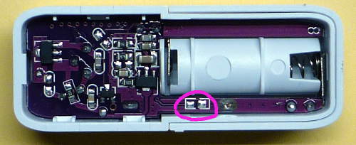
-
In wall light switch node - Custom PCBFor more than two switches see: http://www.gammon.com.au/forum/?id=11091
I would add a hardware debouncing (R/C) to avoid the problems mentioned in the article. -
Trouble sending message to Relay from OpenhabIs there a Serial.begin in your Arduino Code?
-
Good-looking way to control dimmer?Yes, you need something to turn or to press. I would realize this with 2 parts: A MySensors device as "sensor" at the wall and another MySensors device as "actor" near the dimmer which controls the dimmer. Benefits: a better energy efficiency; no deal with 230V; ability to integrate a "controller software" like OpenHAB for further possibilities.
-
Good-looking way to control dimmer?I wood choose a power supply with a PWM Dimm Input. Then you have only to handle with low Voltage (10V). To control the power supply you only need an arduino and an optocopler.
MeanWell Power Supplys: http://www.trcelectronics.com/Meanwell/power-supply-led-dimmable.shtml
You have to choose one with the required power and with "constant voltage". The Aliexpess Part is a constant voltage supply too - I think. Chinese Sellers often don't know what they sell! -
battery level doesn't appear ?"Battery Level" is a internal message.
See: http://www.mysensors.org/download/serial_api_15
This means it is going to the gateway and nobody knows what the gateway is doing with it...
Please correct me if I am wrong. -
Openhab issue: Error during the execution of rule 'Arduino sends to Openhab': 5I have not checked your code. But opening "{" and closing "}" brackets should have the same count.
-
Adding a light switch to Openhab/MQTT gatewayHello,
I'm using exact the same statement. In addition I have a mapping statement. Don't ask if this is necessary.
My line:
{mqtt=">[mysensor:MyMQTT/1/1/V_LIGHT:command:ON:1],>[mysensor:MyMQTT/1/1/V_LIGHT:command:OFF:0],<[mysensor:MyMQTT/1/1/V_LIGHT:command:MAP(1on0off.map)]"}The content of file 1on0off.map in folder /configurations/transform:
1=ON
0=OFF -
MQTT & openhab... but "netstat -an" should work!
-
MQTT & openhabI use a client ( MQTT.fx http://www.jensd.de/wordpress/?cat=50 ) to test the mqtt gateway. Please see my post: http://forum.mysensors.org/topic/953/how-to-know-the-node-ids-assigned-by-the-mqtt-gateway-to-the-sensors/2
With this tool I can see if the gateway is working and which id's are used. Then I configure OpenHAB accordingly.
-
MQTT & openhabI'm not shure what your configuration is. You have:
- a sensor node
- a repeater Node
- a serial / MQTT Gateway node
3 nodes - is this OK?
Or is your sensor node the repeater too. I don't know if this is possible.
In case of a repeater node I'm not shure but I think the gateway is allways the "master" of all id's.
-
MQTT & openhabThe node id is from the gateway. The child id is given by you in your sketch.
-
Someone Explain the Fields in send: 10-10-0-0 s=0,c=1,t=0,pt=7,l=5,st=ok:13.810-10-0-0 | | | | | | | Id of Destination node | | ID of next node | Id of last node this message passed Id of sender node (origin) s = child-sensor-id, 255 für "interne" Messages c = message-type t = sub-type pt = payload-type (see MyMessage.h) l = length of payloadValues c,t,pt: see http://www.mysensors.org/download/serial_api_13
-
MQTT & openhab"20" is the node id of the sender. Your node id is 10. See: "send: 10-10-0-0 s=255,c=0,t=18,pt=0,l=5,st=ok:1.4.1"
"10" is the child id of this particular sensor. Your node has the child id's:
- "0" : send: 10-10-0-0 s=0,c=1,t=0,pt=7,l=5,st=ok:13.8
- "1" : send: 10-10-0-0 s=1,c=1,t=23,pt=3,l=2,st=ok:79
- "2" : send: 10-10-0-0 s=2,c=1,t=1,pt=7,l=5,st=ok:93.0
20-20-0-0 | | | | | | | Id of Destination node | | ID of next node | Id of last node this message passed Id of sender node (origin) s = child-sensor-id, 255 für "interne" Messages c = message-type t = sub-type pt = payload-type (see MyMessage.h) l = length of payload -
Newbie question : how to toggle a led with MQTTat 1) The RelaisActor sketch works out of the box. There is nothing to add. (I think :-) )
at 2) You are right. I don't know "MQTTLens" (I use MQTTfx) but it should be another Input Field for the payload. "1" means Relais on, "0" means off. -
Data from MQTT Gateway not pushing to OpenHab@Jransom2 Unless I'm very much mistaken there is no temperatur message in the lines after "Started!".
During the last day several users of OpenHAB / MQTT had a problem with the first connection. A good tool for debugging is the MQTT client from jerady.
See my posting here: http://forum.mysensors.org/topic/953/how-to-know-the-node-ids-assigned-by-the-mqtt-gateway-to-the-sensors/ -
Connect humidity sensor to OpenHAB@vladimir No, I use a WIZ5100 module. Search the forum. Many users (try) :-)) to use ENC28J60.
-
Connect humidity sensor to OpenHAB@vladimir I had the same problem. Very helpful for me is the MQTT-client MQTT.fx. It shows you the messages from your gateway.
See my post: http://forum.mysensors.org/topic/953/how-to-know-the-node-ids-assigned-by-the-mqtt-gateway-to-the-sensors