Navigation

    • Register
    • Login
    • OpenHardware.io
    • Categories
    • Recent
    • Tags
    • Popular
    1. Home
    2. yury
    3. Posts
    • Profile
    • Following
    • Followers
    • Topics
    • Posts
    • Best
    • Groups

    Posts made by yury

    • RE: MySensors Error received

      @TurboMaster66 said in MySensors Error received:

      item type not found

      Seems like some sensor types you created in those nodes not supported\accepted by the controller. try different types. That is my best guess. I've seen something like that in homeassistant and domoticz

      posted in Indigo Domotics
      yury
      yury
    • RE: MySensors Error received

      @TurboMaster66

      Do you have nodes with addresses ## 17 60 100 on your network?

      posted in Indigo Domotics
      yury
      yury
    • RE: Gateway sends NACK to node

      @mariusl said in Gateway sends NACK to node:

      what it does

      SF number is chips (chirps) needed to code each bit. SF4096 is maximum range especially in urban area, but very long delay . I tried different combinations and found below MY_RFM95_MODEM_CONFIGRUATION is pretty much good. 20 - 30% less in terms of distance and delay #define RFM95_RETRY_TIMEOUT_MS (300ul) is enoght. Much faster.

      #define MY_RFM95_MODEM_CONFIGRUATION RFM95_BW_500KHZ | RFM95_CODING_RATE_4_5, RFM95_SPREADING_FACTOR_2048CPS | RFM95_RX_PAYLOAD_CRC_ON, RFM95_AGC_AUTO_ON

      posted in Troubleshooting
      yury
      yury
    • RE: Gateway sends NACK to node

      @mariusl said in Gateway sends NACK to node:

      good value for the timeout?

      here are the delay examples in the docs
      https://www.mysensors.org/apidocs/group__RFM95grp.html#ga23a30185cbd40984e65d5269983bf840

      for yours #define MY_RFM95_MODEM_CONFIGRUATION RFM95_BW125CR48SF4096

      I would use #define RFM95_RETRY_TIMEOUT_MS (2000ul)

      any reason for the Spread factor SF4096 ?

      posted in Troubleshooting
      yury
      yury
    • RE: Gateway doesn't receive any message from node

      pinout looks ok.

      btw This line from the Node log

      1269 !TSF:MSG:SEND,100-100-0-0,s=255,c=3,t=24,pt=1,l=1,sg=0,ft=0,st=NACK:1

      Means node cannot send OR gateway cannot receive. may be node radio is HCW somehow?
      mysensors lib not broken\timeouts not tweaked?

      posted in Troubleshooting
      yury
      yury
    • RE: Gateway doesn't receive any message from node

      @ctodor said in Gateway doesn't receive any message from node:

      broken only on the "send side"

      As @mfalkvidd said, it is possible to burn with no antenna attached but I never actually did that. RFM is quite reliable. Is Schematics available? I see you have reset pad soldered. reset should be disconnected after reset is completed.

      posted in Troubleshooting
      yury
      yury
    • RE: Gateway doesn't receive any message from node

      @ctodor said in Gateway doesn't receive any message from node:

      I bought from you, "easySensor"

      Yes. πŸ‘

      may be detailed photo of the device can help...

      posted in Troubleshooting
      yury
      yury
    • RE: Gateway sends NACK to node

      @mariusl said in Gateway sends NACK to node:

      Any ideas from someone on this?

      #define MY_TRANSPORT_STATE_TIMEOUT_MS (5*1000ul)

      //#define MY_RFM95_MODEM_CONFIGRUATION RFM95_BW125CR45SF1288
      #define MY_RFM95_MODEM_CONFIGRUATION RFM95_BW125CR48SF4096

      These lines can affect. the TRANSPORT_STATE_TIMEOUT may be less than a actual message sending time. you will get constant NACK's.

      posted in Troubleshooting
      yury
      yury
    • RE: Gateway doesn't receive any message from node

      @ctodor said in Gateway doesn't receive any message from node:

      GW ia not totally mute

      Better to have 3-rd device to play with. Preferably 3.3 V one. RFM is 3.3 volts radio. not sure if you used logic level shifters for Nano digital pins connected to radio. Also, SDR radio is handy to detect any radio emission.

      posted in Troubleshooting
      yury
      yury
    • RE: Gateway doesn't receive any message from node

      which radio version do you use HCW or CW?

      #define MY_IS_RFM69HW // this is for HCW or commnet out for CW

      posted in Troubleshooting
      yury
      yury
    • RE: πŸ’¬ Button size radionode with sensors swarm extension

      @bjornhallberg

      while measuring current draw , was there FDTI adapter connected also?

      posted in OpenHardware.io
      yury
      yury
    • RE: Very strange bugs. 2.3. RFM69.

      @alexsh1
      I was trying the same code on bare RFM69 board without any external libs,
      just mysesnsors2.0 and 2.2 and 2.3 old drivers. 2.0 need 30ms waits 2.2-2.3 - up to 100ms for stable ACK's and sends

      @scalz
      NRF24 works fine without waits.... may be you know some direction where to dig in RFM driver for gold?

      posted in Troubleshooting
      yury
      yury
    • RE: Very strange bugs. 2.3. RFM69.

      @mickecarlsson said in Very strange bugs. 2.3. RFM69.:

      Note that the begin() function needs a mode parameter, and that is used in configure

      Should be this one lightMeter.begin(BH1750::ONE_TIME_LOW_RES_MODE); but Koresh was asking radio related question...

      posted in Troubleshooting
      yury
      yury
    • RE: πŸ’¬ EASY PIR multisensors box

      0_1528923175153_9bfda433-3e4a-4e5b-acf7-5aaa7fe96fad-image.png
      0_1528923208297_97719b33-6c08-4556-b40f-9b84d63d5197-image.png

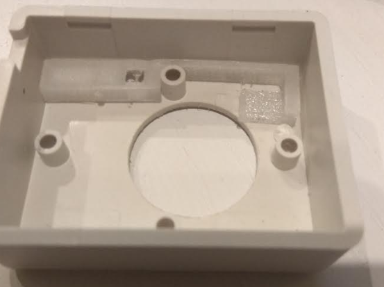
      ESUN flex filament used.

      posted in OpenHardware.io
      yury
      yury
    • RE: πŸ’¬ Button size radionode with sensors swarm extension

      @kenci

      EUR 18 the board with SI7021 and BH1750. extra 1EUR for enclosure if someone need it.

      posted in OpenHardware.io
      yury
      yury
    • RE: πŸ’¬ Button size radionode with sensors swarm extension

      @kenci

      Yes, in a week or so. Even with plastic enclosure ))
      1_1523479667076_IMG_20180411_231150_cr.jpg
      0_1523479667075_IMG_20180411_231446_cr.jpg

      posted in OpenHardware.io
      yury
      yury
    • RE: πŸ’¬ Button size radionode with sensors swarm extension

      @gohan said in πŸ’¬ Button size radionode with sensors swarm extension:

      selected it will go out of range during node boot and cut the circuit making measurement impossible

      my cheap one survives 20mA surge (RFM69 CW version) of initial communications and displays good reading afterwards. if you burned fuse inside, try replacing it temporarily with some thin wire for this uA tests.

      posted in OpenHardware.io
      yury
      yury
    • RE: πŸ’¬ Button size radionode with sensors swarm extension

      @chbla said in πŸ’¬ Button size radionode with sensors swarm extension:

      multimeter

      You should be fine even with a cheap multi-meter as long as it has uA scale.

      should be around 7-10 uA and if you do not send JDEC to sleep it is 17 -19 uA.

      to send JDEC to sleep\wakeup I use
      _flash.wakeup();
      _flash.sleep();

      light sensor should be sent to sleep explicitly also.

      posted in OpenHardware.io
      yury
      yury
    • RE: πŸ’¬ Button size radionode with sensors swarm extension

      @neverdie said in πŸ’¬ Button size radionode with sensors swarm extension:

      worth

      uh... apparently, yes. dual dip cr2032 is hard to find item on ali.

      posted in OpenHardware.io
      yury
      yury
    • RE: πŸ’¬ Button size radionode with sensors swarm extension

      Re: πŸ’¬ Button size radionode with sensors swarm extension

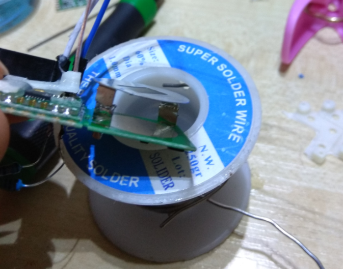
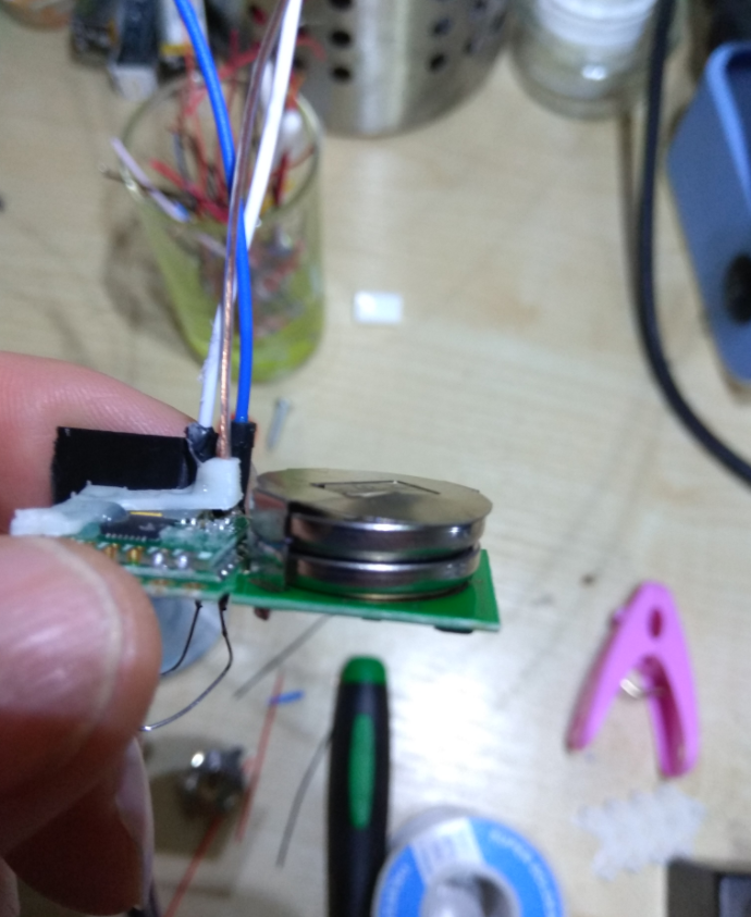
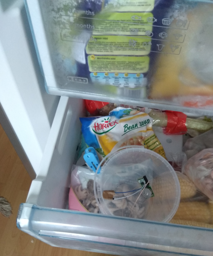
      2 cr2032 winter upgrade - works nice

      Keep working at -20 Celsius in a fridge. voltage dropped from 6 Volts to 5V and keeps pretty stable while sending temperature reading every 2 minutes for 2 days now.

      0_1513507522799_f6cf3141-ea91-4c31-a320-25cb0c65b5c7-image.png

      0_1513507559378_5e5573f0-b189-4faf-8766-04a367242e68-image.png

      0_1513507573427_c616c24a-9224-4a52-80d4-7e5984ffcf86-image.png

      0_1513507583720_3d6261ad-5c43-4c25-b43d-50bf21631672-image.png

      0_1513507722585_b9338c01-ed9d-4f3e-8f39-21fd4d78f713-image.png

      posted in OpenHardware.io
      yury
      yury
    • RE: πŸ’¬ Wall Socket Insertable Node

      @kalina said in πŸ’¬ Wall Socket Insertable Node:

      @yury What do you think about capacitive button "On/Off" to the right corner from led? Look at the pic below...
      0_1511511651983_upload-94807368-e9e7-4f89-97ea-1d5f8ac468ff

      Looks cool! Do you have experience with capacities switches? I did not play much with them. afraid to use close to AC interference though...

      posted in OpenHardware.io
      yury
      yury
    • RE: πŸ’¬ Wall Socket Insertable Node

      @jeremushka said in πŸ’¬ Wall Socket Insertable Node:

      Have you ever had feature as power meter?

      there is ACS712ELCTR-20A AC current sensing chip on the board. but Atmega ADC not very accurate at low currents reported from ACS712 - 20A. 15W loads or less can be difficult to recognize.

      BTW another idea for LED indication . There is installed pixel LED on-board. check pictures. it is bright enough

      0_1511469223333_upload-577ef824-0975-464f-bf71-01508746a49f

      0_1511468966659_upload-959c7ab7-b86d-47bc-b50f-84bb42d7f16b

      0_1511469249412_upload-ac69c082-8e14-4fb8-9e2f-0f45acc58f7a

      0_1511469335265_upload-34073147-3f54-409c-a7cc-1999a990b7f8

      posted in OpenHardware.io
      yury
      yury
    • RE: πŸ’¬ Wall Socket Insertable Node

      0_1511423252215_upload-58b63f65-387b-4f09-8ecc-8e502167df7c

      0_1511423242157_upload-b3e8f1c1-6885-49a9-bc85-9a031bec40a6

      make sense?

      sketch is here
      https://github.com/EasySensors/WallSocketInsertableNode/blob/master/WallSocketInsertableNode.ino

      but no LED support there, but easy to add.
      Yes, it will work if no gateway around.

      posted in OpenHardware.io
      yury
      yury
    • RE: πŸ’¬ Wall Socket Insertable Node

      @jeremushka

      Assume you need to use it with some kind of momentary or rocker switch in case you lose connection to the gateway. Use JST connector and enable A2 internall pullup. JST connector pins are A2 and ground.

      posted in OpenHardware.io
      yury
      yury
    • SPI flash chip is not sleeping during sleep.

      The flash chip supposed to go sleep if the node sent to sleep but it is not and eats extra 10uA. I did not go deep into the lib code but found if I send the node to sleep "manually" it eats only 7 uA - no LDO, 10 uA with LDO.

      SPIFlash flash(8, 0x0);
      
      void loop()
      {
        //wdt_reset();
       //swarm_report();      
        flash.sleep();
        sleep(600000);
      }
      

      Am I missing something ?

      SPI flash sleep mentioned here:
      https://github.com/mysensors/MySensors/blob/master/drivers/SPIFlash/SPIFlash.h#L91

      posted in Troubleshooting
      yury
      yury
    • RE: πŸ’¬ Wall Switch Insertable Node

      @Sefi-Ninio said in πŸ’¬ Wall Switch Insertable Node:

      Hey @yury , thanks for the reply!
      The pictures were very helpful πŸ™‚

      Does this board come flashed with the alternate bootloader that supports OTA updates?

      yes, comes with dualoptiboot. but the code is very basic and sends to sleep right after button pressed. So need some additional code to keep it awake to wait for OTA to receive.

      posted in OpenHardware.io
      yury
      yury
    • RE: πŸ’¬ Wall Switch Insertable Node

      @Sefi-Ninio

      Hi Sefi,

      if you like to put some additional extra switch somewhere you can use this funny way:

      0 02 04 a4d1560b69c0e8f5a4ab4016107b71cb194b23b29f6dbdfb2bcb6a5c14a7713f full – 01:13
      β€” YurySvirida

      if you like to use the one in the wall, this way may work for you:

      In both ways you need to have something that receives signal from the switch - a relay node.

      3 easy steps as usual ))))

      1. Π‘onnect any connector (J1-J4) to a switch terminals and glue them together with self adhesive or Velcro or glue gun....
      1
      1

      2. Connect wires from the wall together. Now you power up the Relay node which controls a bulb in the ceiling.
      2

      3. Install the switch and the switch node back into the wall.
      3

      let me know if it is clear for you. I mean the Relay node part.

      safety first - power down the switch before removing it.

      posted in OpenHardware.io
      yury
      yury
    • RE: πŸ’¬ Button size radionode with sensors swarm extension

      @Abdu-Sahin said in πŸ’¬ Button size radionode with sensors swarm extension:

      Battery life is important

      sent you a message in the chat...

      posted in OpenHardware.io
      yury
      yury
    • RE: πŸ’¬ Button size radionode with sensors swarm extension

      @Abdu-Sahin said in πŸ’¬ Button size radionode with sensors swarm extension:

      I need sensors with long battery life and good RF distance coverage

      )) either good battery life or good coverage though... or good coverage and 2-3 AA batteries. CW is 20 mA when sending signal and HCW is about 100 mA. CR2032 battery will be drained by HCW pretty fast.
      HW/W versions have bigger footprints (Module Size:19.7X16mm) and not compatible with the "Button size".
      HCW/CW (Module Size:16X16mm) are equivalents for HW/W.

      posted in OpenHardware.io
      yury
      yury
    • RE: πŸ’¬ Button size radionode with sensors swarm extension

      @Abdu-Sahin said in πŸ’¬ Button size radionode with sensors swarm extension:

      865mhz HW/

      Hi

      They will be ready end of this week. do you need both HCW and CW versions?

      posted in OpenHardware.io
      yury
      yury
    • RE: πŸ’¬ Wall Switch Insertable Node

      @jeremushka said in πŸ’¬ Wall Switch Insertable Node:
      " if the circuit has some problems"

      Could please elaborate more on your findings? Did you notice any bugs in the code or in schematics?

      posted in OpenHardware.io
      yury
      yury
    • RE: πŸ’¬ Button size radionode with sensors swarm extension

      @alexsh1 said in πŸ’¬ Button size radionode with sensors swarm extension:

      Did you test power consumption of modules with Si1132 please? I hope it was a bad soldering on my side

      Could not find good code to send it to sleep. without it Si1132 was eating a lot...

      posted in OpenHardware.io
      yury
      yury
    • RE: πŸ’¬ Button size radionode with sensors swarm extension

      @alexsh1

      @alexsh1 said in πŸ’¬ Button size radionode with sensors swarm extension:

      @yury said in πŸ’¬ Button size radionode with sensors swarm extension:

      @alexsh1 220 mAh(Duracell) / 0.025 (mA) = 8800 hrs = 366 days.

      Not exactly - 25uA is a sleeping current.
      There will be sending periods every 10 mins.
      So I suppose the lifetime is less than a year

      Yes, it is sleeping time estimate. When it wakes up it compares first, like : if ( abs(d) > 50 ) send(msg_vis.set(VIS_LIGHT), true); so it might send or not.
      But this is just example sketch and you are very welcome to create pull-request or make suggestion how to improve.

      posted in OpenHardware.io
      yury
      yury
    • RE: πŸ’¬ Button size radionode with sensors swarm extension

      @alexsh1 220 mAh(Duracell) / 0.025 (mA) = 8800 hrs = 366 days.

      posted in OpenHardware.io
      yury
      yury
    • RE: πŸ’¬ Button size radionode with sensors swarm extension

      0.4 ma here with the bad cap
      0_1499269945983_viber image.jpeg

      posted in OpenHardware.io
      yury
      yury
    • RE: πŸ’¬ Button size radionode with sensors swarm extension

      combined capacitance of booth should be 100 --200 microfarads . It is input capacitors.
      please try replacing them

      re:
      I was suspecting EEPROM (CS pin with pull-up resistor?) to be a culprit

      not pullups...

      posted in OpenHardware.io
      yury
      yury
    • RE: πŸ’¬ Button size radionode with sensors swarm extension

      @alexsh1 said in πŸ’¬ Button size radionode with sensors swarm extension:

      Something else is eating up a few milliamps

      yes seems your board has bad capacitors. After rechecking many boards we found one eating a lot - 0.4 mA. Replacing caps fixed issue.

      2_1499267230472_noLDO.jpg 1_1499267230472_LDO.jpg 0_1499267230471_gooodCap.jpg

      can you check?

      posted in OpenHardware.io
      yury
      yury
    • RE: πŸ’¬ Button size radionode with sensors swarm extension

      @alexsh1 said in πŸ’¬ Button size radionode with sensors swarm extension:

      it on the first day I got

      Could you post the code you use? and links for the libs. we will check tomorrow consumption with your code . mysensors 2.0 or 2.2?

      posted in OpenHardware.io
      yury
      yury
    • RE: Fighting RFM 69 NACK's

      @mfalkvidd said in Fighting RFM 69 NACK's:

      like there is a lot of activity on the 433 band. Do you have any idea

      really no clue. it is started like this (different zoom):
      0_1495316193107_nooiseStart.jpg

      posted in Troubleshooting
      yury
      yury
    • Fighting RFM 69 NACK's

      Once a week I was having NACK blackout. All nodes could not send nor receive anything. Initially I was resetting everything and after some 20 minutes I was β€œable to fix” things. However, it was reappearing. Looked very strange. I bought very very very useful device called RTL-SDR (R820T) software digital receiver. Just in case you do not have, it is worth to buy. Yes, it is around $7 dollars from aliexpress include delivery. The device is not good for NRF since range is 24 - 1766 MgHz but for RFM it is super good. Back to my problem though, I found the noise at 429 -437 Mghz and it lasts around 20 minutes, the time β€œI was fixing things” previously. Huh!
      Video
      https://youtu.be/BH_hDyWGr5I
      You can see from the video, blackout was at the frequencies from 429 -437 Mghz
      After that, I switched RFM 69 to 440 Mghz and see results. 5 transmissions!!!
      https://youtu.be/jlE2p07-jOY
      The device is super useful toy!!! You can listen FM radio and other air traffic control towers.
      Found later is not legal to use 440 Mghz though…
      The RTL-SDR (R820T):
      With this tutorial you can turn RTL-SDR (R820T) into 24 - 1766 MgHz receiver and see what happens in the air.
      http://www.rtl-sdr.com/rtl-sdr-quick-start-guide/

      0_1495314594386_P_20170520_210119(1).jpg
      Hope it is helpful.

      posted in Troubleshooting
      yury
      yury
    • RE: Help: Some explanation requested regarding NACK

      @Omemanti said in Help: Some explanation requested regarding NACK:

      but my

      Could you post part of the code where you send those messages? do you send the node to sleep?

      posted in Troubleshooting
      yury
      yury
    • RE: πŸ’¬ Wall Socket Insertable Node

      Hi @fisher yes this is Koresh board. Hope to upload others soon... We did production and testing with him together.

      posted in OpenHardware.io
      yury
      yury
    • RE: [Solved] Strange behavior of RFM69 OTA burning firmware after some research

      The bootloader and OTA update script + RFM69 work super nice with MYScontroller. I use it few times a week. Big Big Big ups to Tekka. Especially I like the sensebender micro bootloader boots instantly ))). Enjoy everybody!

      posted in Bug Reports
      yury
      yury
    • RE: [Solved] Strange behavior of RFM69 OTA burning firmware after some research

      @tekka

      with your new PR updated all works good now. I could not replicate @ 40 ms in retryWaitTime the mentioned above. so I put 10 ms like a stress test. It has survived! with lots of WRONG FWB but with CRC OK!

      the logs

      serial
      https://drive.google.com/open?id=0B11zpaGZaUo5c3NMT1VuSGoxU3c

      last OTA is correspoding to serial log
      https://drive.google.com/open?id=0B11zpaGZaUo5MVh2cUg2cWMxWER0aHEwWHhoY1VidEpuOURn

      posted in Bug Reports
      yury
      yury
    • RE: [Solved] Strange behavior of RFM69 OTA burning firmware after some research

      I will reproduce tonight. with MYSController log.

      posted in Bug Reports
      yury
      yury
    • [Solved] Strange behavior of RFM69 OTA burning firmware after some research

      Found strange behavior of RFM69 OTA burning firmware after some research
      OTA + RFM 69 (possible) glitches.
      Used MYScontroller – works super flawless
      Tried both MySensors Library 2.0 and MySensors Library v2.1.0
      Various boards made by Koresh 8 Mghz Atmega with RFM69 radios

      The issue: On larger sketches (like more than 20kbytes), OTA always gives CRC error. Smaller ones (4k or less) could be burned 1 out of 3 tries.

      In the picture below the blues screen is comparing two files (right column is HEX and two lines actually is single 16 bit OTA payload)
      Bin.txt file is parsed Arduino hex output to the way it is identical to JDEC flash content. TXT2 file is JDEC flash content.
      Log indicates NACK error for the block B=0065 and LEN !=29 (assume it is 0 length payload). After that, somehow instead of re-requesting that corrupted or 0 sized payload, it duplicates previously received (marked in yellow) into new address. This can happen sometimes 2-3 or 10 times during OTA process

      0_1483446249615_ota.jpg

      I spend many hours playing with MyOTAFirmwareUpdate , transport and RFM driver trying β€œfixing” logic there but failed. Solution found Koresh by increasing from 40ms to 100ms retryWaitTime in RFM69.h

      virtual bool sendWithRetry(uint8_t toAddress, const void* buffer, uint8_t bufferSize,  uint8_t retries=2, uint8_t retryWaitTime=100); //!< sendWithRetry (40ms roundtrip req for 61byte packets) 
      

      So may be something strange happens when rfm ack is received outside the circle in sendWithRetry function.

      My and Koresh concern it is not β€œreal” solution. Since this kind of re-requesting of 0 sized payloads should be dealt very well in protocol layer. Otherwise if there is lots of traffic going on
      In the network, there will be lots of this kind of 0 payload situations.
      The fix actually gives good results (10 out of 10 without CRC errors). It works now but… I think would be great to look into deeply.

      @tekka

      posted in Bug Reports
      yury
      yury
    • RE: πŸ’¬ Wall Switch Insertable Node

      We are changing PCBA contractor which is supposed to assemble Koresh projects. Since current one gave us way too many errors while assembling other projects for our "Day Job" we work with Koresh together. so may be some delay for all Koresh projects.

      posted in OpenHardware.io
      yury
      yury
    • RE: πŸ’¬ Wall Socket Insertable Node

      @PierreSt

      www.aliexpress.com/item/55-22mm-5pcs-LED-ceiling-circular-drive-casing-fire-retardant-PC-power-supply-housing-with-cooling/32643161481.html?spm=2114.13010608.0.72.VRC6ws

      is the smallest. will get them soon. not sure if the thing will fit inside though.

      So far we a bit stuck with our PCBA contractor. Negotiating hard for better prices.

      posted in OpenHardware.io
      yury
      yury
    • RE: πŸ’¬ Wall Socket Insertable Node

      @fisher said:

      Putting raw electronics to tight wall socket is not the safest solution

      We think to use as "standalone case" this one:

      https://www.alibaba.com/product-detail/72-25-mm-LED-drive-power_60426277938.html?spm=a2700.7724838.0.0.QARRdD

      As for safety in "tight wall socket", the point here is:

      1. All those wall socket boxes is really safe Ip 20 or 44 certified together with socket itself.
      2. If something happens inside this crimped space will stay there.

      This node will have thermal fuse, Over-voltage varistor, and if you short cut the relay - ACS 712 has build in "fuse".

      So I think inside a wall is still much safer. How to put it safely there - it is another topic. At least you have to have experience in fixing things at home and for sure cut off power!

      I tried to burn this thing many times as we tested it. so far most impressive was relay short cut test. Re-soldering new ACS712 fixed thing back. Relay survived also.

      0_1472296685047_2016-08-27_14-07-16.png

      Traces of the test on the case. Not even melting traces, just smoked out:
      0_1472296864373_2016-08-27_14-07-28.png

      posted in OpenHardware.io
      yury
      yury
    • RE: πŸ’¬ Wall Socket Insertable Node

      @fisher are you referring to touch sensor button or momentary push button?

      posted in OpenHardware.io
      yury
      yury
    • RE: πŸ’¬ Button size radionode

      @hek

      Does RFM69 really need to be connected to D2? Does Mysensors lib use it ?

      posted in OpenHardware.io
      yury
      yury
    • RE: Two serial gateways: 1-st for NRF and 2-nd for RFM69 radios. Is it possible?

      "variable type is not visible in hardware interface" it has been updated after some time also. Now it is visible.

      posted in Domoticz
      yury
      yury
    • RE: Two serial gateways: 1-st for NRF and 2-nd for RFM69 radios. Is it possible?

      @mfalkvidd - Thanks again!

      after update all is good now. No mess. I was pressing update as beta release for a few month but there were no updates available.... last night found there is stable available! cool.

      just for debugging if anyone interested - I noticed variable type is not visible in hardware interface for serial gateway 2.0. But that is ok. All works good

      0_1462428171642_2016-05-05_8-50-59.png
      0_1462428239996_2016-05-05_8-56-09.png
      0_1462428273920_2016-05-05_8-50-37.png

      posted in Domoticz
      yury
      yury
    • RE: Two serial gateways: 1-st for NRF and 2-nd for RFM69 radios. Is it possible?

      Ok. I will update it later today. Thanks for helping!

      re:
      Would be interesting to see what it looks like when the rfms are added.

      there will be instead of "Mysensors" the "RFM" gateway name whatever I named it.

      posted in Domoticz
      yury
      yury
    • RE: Two serial gateways: 1-st for NRF and 2-nd for RFM69 radios. Is it possible?

      the "mess"
      Encircled in red are NRF radio sensors. If I add RFM gateway and two RFM radio connected sensors domoticz devices page starts to show all NRF radio based sensors like they are working through RFM gateway. In the encircled red column "Hardware" there will be different gateway names. Consequently, all system not sending or receiving any messages correctly.
      0_1462347011201_2016-05-04_10-03-01.png

      posted in Domoticz
      yury
      yury
    • Two serial gateways: 1-st for NRF and 2-nd for RFM69 radios. Is it possible?

      I tried but got some mess in the device list.

      posted in Domoticz
      yury
      yury
    • RE: πŸ’¬ MySensors Stable Node

      @Slorf said:

      reply

      Congrats and enjoy ))

      posted in OpenHardware.io
      yury
      yury
    • RE: πŸ’¬ MySensors Stable Node

      @Sander-Teunissen said:

      You make some... I'll buy some... great work!

      So far still negotiating\finding reliable PCBA. First batch of 17 boards Koresh and me we were not impressed.

      posted in OpenHardware.io
      yury
      yury
    • RE: πŸ’¬ MySensors Stable Node

      Alfa testing:

      Checking radios as various nodes. Currently working as 2 relay nodes, DHT 22 temperature node and gateway.
      All is good . Range 1-2 meters less than NRF24 with big antenna in apartment surrounding.
      Digital pins cheeked like in the video: https://youtu.be/00fy9amZnt4
      Analog pins tested with generic arduino light sensor. So radios and pins are OK.

      posted in OpenHardware.io
      yury
      yury
    • RE: πŸ’¬ MySensors Stable Node

      @ahmedadelhosni said:

      Is soldering it more difficult than soldering the atmega as they are not the same package type ?

      3 steps process:

      1. tin-plating the board contacts
      2. tin-plating the chip contacts
      3. apply flux-gel and place chip on the board and heat it with soldering Heat Blower - pre-heat-wait-heat-wait . Like standard soldering profile http://www.renesas.eu/products/lead/specific_info/rt/heatproof/index.jsp .

      also need to have a good ayes ))) the flux-gel should be the one you do not have to remove after.

      posted in OpenHardware.io
      yury
      yury
    • RE: πŸ’¬ MySensors Stable Node

      So far betatests for two modules soldered manually two weeks ago are good. I was using two analog inputs and 5 digital outputs. Radio is rock stable also.0_1457364082654_1745f59fdda935cd02a9fcf4f5f741a256b98564f4610991d6c502bc6aec6aa6.jpg

      posted in OpenHardware.io
      yury
      yury
    • RE: πŸ’¬ MySensors Stable Node

      re: pay +$300 as a startup fee

      no no nooo . Hope to find it cheaper. I think they can do it manually @ $1 per board or so. plus some quality control.

      posted in OpenHardware.io
      yury
      yury
    • RE: πŸ’¬ MySensors Stable Node

      The break down cost of the board and components is less than USD $5 ( aliexpress component prices mostly) . Can someone share some PCBA service which can also do components sourcing ? with reasonable pricing of course. I would order some 20 - 30 units and may be others could join to make price cheaper.

      posted in OpenHardware.io
      yury
      yury
    • RE: Domoticz and ACK

      Hello,

      Everything is OK. It was my mistake.
      I did not do clear EPROM properly... so I ended up with the repeater and the node with the same nodeID which I hard coded. That is why repeater ACK was accepted as node ACK.

      All work great.

      posted in Domoticz
      yury
      yury
    • RE: Domoticz and ACK

      Super!!!

      One little issue I found so far. If there is a repeater used between the node and the gateway, somehow domoticz accept ack from from repeater even if node is off line.

      Otherwise it works very nice.

      posted in Domoticz
      yury
      yury
    • RE: Domoticz and ACK

      Hello @NewFolk !

      Not yet.

      Thanks for your post in domoticz forum!

      posted in Domoticz
      yury
      yury
    • Domoticz and ACK

      Is there any way to make Domoticz read back acknowledgements from relay nodes when you turn them on or off? Like when you press on and if radio fails GUI icon will show as it is off.

      posted in Domoticz
      yury
      yury
    • RE: relay actuator fails to presenting itself

      Hek, you are the best!

      I plug all three things into my laptop to be able to see all logs and actuator (55) appeared in the serial gateway log

      0;0;3;0;9;gateway started, id=0, parent=0, distance=0
      0;0;3;0;14;Gateway startup complete.
      0;0;3;0;9;read: 5-5-0 s=255,c=0,t=18,pt=0,l=3,sg=0:1.5
      5;255;0;0;18;1.5
      0;0;3;0;9;read: 5-5-0 s=255,c=3,t=6,pt=1,l=1,sg=0:0
      5;255;3;0;6;0
      0;0;3;0;9;read: 55-5-0 s=255,c=0,t=17,pt=0,l=3,sg=0:1.5
      55;255;0;0;17;1.5
      0;0;3;0;9;read: 55-5-0 s=255,c=3,t=6,pt=1,l=1,sg=0:5
      55;255;3;0;6;5
      0;0;3;0;9;read: 5-5-0 s=55,c=0,t=3,pt=0,l=0,sg=0:
      5;55;0;0;3;
      0;0;3;0;9;read: 5-5-0 s=55,c=1,t=2,pt=2,l=2,sg=0:1
      5;55;1;0;2;1
      0;0;3;0;9;read: 55-5-0 s=255,c=3,t=11,pt=0,l=5,sg=0:Relay
      55;255;3;0;11;Relay
      0;0;3;0;9;read: 55-5-0 s=255,c=3,t=12,pt=0,l=3,sg=0:1.0
      55;255;3;0;12;1.0
      0;0;3;0;9;read: 55-5-0 s=55,c=0,t=3,pt=0,l=0,sg=0:
      55;55;0;0;3;

      repeater (5) log also showing it
      send: 5-5-0-0 s=255,c=0,t=18,pt=0,l=3,sg=0,st=ok:1.5
      send: 5-5-0-0 s=255,c=3,t=6,pt=1,l=1,sg=0,st=ok:0
      repeater started, id=5, parent=0, distance=1
      send: 5-5-0-0 s=55,c=0,t=3,pt=0,l=0,sg=0,st=ok:
      send: 5-5-0-0 s=55,c=1,t=2,pt=2,l=2,sg=0,st=ok:1
      read: 55-55-0 s=255,c=0,t=17,pt=0,l=3,sg=0:1.5
      send: 55-5-0-0 s=255,c=0,t=17,pt=0,l=3,sg=0,st=ok:1.5
      read: 55-55-0 s=255,c=3,t=6,pt=1,l=1,sg=0:5
      send: 55-5-0-0 s=255,c=3,t=6,pt=1,l=1,sg=0,st=ok:5
      read: 55-55-0 s=255,c=3,t=11,pt=0,l=5,sg=0:Relay
      send: 55-5-0-0 s=255,c=3,t=11,pt=0,l=5,sg=0,st=ok:Relay
      read: 55-55-0 s=255,c=3,t=12,pt=0,l=3,sg=0:1.0
      send: 55-5-0-0 s=255,c=3,t=12,pt=0,l=3,sg=0,st=ok:1.0
      read: 55-55-0 s=55,c=0,t=3,pt=0,l=0,sg=0:
      send: 55-5-0-0 s=55,c=0,t=3,pt=0,l=0,sg=0,st=ok:
      send: 5-5-0-0 s=55,c=1,t=2,pt=2,l=2,sg=0,st=ok:0
      send: 5-5-0-0 s=55,c=1,t=2,pt=2,l=2,sg=0,st=ok:1

      understand something wrong was with external power supply.

      the only thing left, actuator(55) not receiving from repeater(5) which is the switch sensor, messages. These two entries

      send: 5-5-0-0 s=55,c=1,t=2,pt=2,l=2,sg=0,st=ok:0
      send: 5-5-0-0 s=55,c=1,t=2,pt=2,l=2,sg=0,st=ok:1

      not getting to actuator...

      posted in Troubleshooting
      yury
      yury
    • RE: relay actuator fails to presenting itself

      55 log looks llike this:

      send: 55-55-5-0 s=255,c=0,t=17,pt=0,l=3,sg=0,st=ok:1.5
      send: 55-55-5-0 s=255,c=3,t=6,pt=1,l=1,sg=0,st=ok:5
      sensor started, id=55, parent=5, distance=1
      send: 55-55-5-0 s=255,c=3,t=11,pt=0,l=5,sg=0,st=ok:Relay
      send: 55-55-5-0 s=255,c=3,t=12,pt=0,l=3,sg=0,st=ok:1.0
      send: 55-55-5-0 s=55,c=0,t=3,pt=0,l=0,sg=0,st=ok:

      posted in Troubleshooting
      yury
      yury
    • RE: relay actuator fails to presenting itself

      added as repeater node 5, but still no traces of the actuator 55 in the gateway.

      send: 5-5-0-0 s=255,c=0,t=18,pt=0,l=3,sg=0,st=ok:1.5
      send: 5-5-0-0 s=255,c=3,t=6,pt=1,l=1,sg=0,st=ok:0
      repeater started, id=5, parent=0, distance=1
      send: 5-5-0-0 s=55,c=0,t=3,pt=0,l=0,sg=0,st=ok:
      send: 5-5-0-0 s=55,c=1,t=2,pt=2,l=2,sg=0,st=ok:1

      posted in Troubleshooting
      yury
      yury
    • RE: relay actuator fails to presenting itself

      re:
      And what does the repeater (5) log look like?

      I do not use repeater. 5 is sample code for switch with hard coded ID == 5

      switch monitor log

      send: 5-5-0-0 s=255,c=0,t=17,pt=0,l=3,sg=0,st=ok:1.5
      send: 5-5-0-0 s=255,c=3,t=6,pt=1,l=1,sg=0,st=ok:0
      sensor started, id=5, parent=0, distance=1
      send: 5-5-0-0 s=55,c=0,t=3,pt=0,l=0,sg=0,st=ok:
      send: 5-5-0-0 s=55,c=1,t=2,pt=2,l=2,sg=0,st=ok:1
      send: 5-5-0-0 s=55,c=1,t=2,pt=2,l=2,sg=0,st=ok:0
      send: 5-5-0-0 s=55,c=1,t=2,pt=2,l=2,sg=0,st=ok:1

      re:
      As you can see (ack fail) the node is having problem communicating with repeater.

      do I need to switch off somewhere repeater mode? I do not need repeater.
      I use
      gw.begin(incomingMessage, NodeID, false,5); in actuator code
      gw.begin(NULL, NodeID, false); in switch code.

      re:
      Also.. are you calling gw.process() in the loop-function on your repeater?

      I added now...

      //  Check if digital input has changed and send in new value
      void loop() 
      {
      
        debouncer.update();
        // Get the update value
        int value = debouncer.read();
       
        if (value != oldValue) {
           // Send in the new value
           gw.send(msg.set(value==HIGH ? 1 : 0));
           oldValue = value;
        }
       gw.process();
      }


      After I added gw.process(); log looks good but still no traeces of actuator in serial gateway.

      Actuator log:
      send: 55-55-5-0 s=255,c=0,t=17,pt=0,l=3,sg=0,st=ok:1.5
      send: 55-55-5-0 s=255,c=3,t=6,pt=1,l=1,sg=0,st=ok:5
      sensor started, id=55, parent=5, distance=1
      send: 55-55-5-0 s=255,c=3,t=11,pt=0,l=5,sg=0,st=ok:Relay
      send: 55-55-5-0 s=255,c=3,t=12,pt=0,l=3,sg=0,st=ok:1.0
      send: 55-55-5-0 s=55,c=0,t=3,pt=0,l=0,sg=0,st=ok:

      posted in Troubleshooting
      yury
      yury
    • RE: relay actuator fails to presenting itself

      Yes. I use switch as parent with ID ==5

      like this :

      #include <MySensor.h>
      #include <SPI.h>
      #include <Bounce2.h>
      
      #define CHILD_ID 55
      #define BUTTON_PIN  5  // Arduino Digital I/O pin for button/reed switch
      
      MySensor gw;
      Bounce debouncer = Bounce(); 
      int oldValue=-1;
      
      // Change to V_LIGHT if you use S_LIGHT in presentation below
      MyMessage msg(CHILD_ID,V_LIGHT);
      
      void setup()  
      {  
        #define NodeID 5
      
        // Initialize library and add callback for incoming messages
        gw.begin(NULL, NodeID, false);


      //  gw.begin();
      
       // Setup the button
        pinMode(BUTTON_PIN,INPUT);
        // Activate internal pull-up
        digitalWrite(BUTTON_PIN,HIGH);
        
        // After setting up the button, setup debouncer
        debouncer.attach(BUTTON_PIN);
        debouncer.interval(5);
        
        // Register binary input sensor to gw (they will be created as child devices)
        // You can use S_DOOR, S_MOTION or S_LIGHT here depending on your usage. 
        // If S_LIGHT is used, remember to update variable type you send in. See "msg" above.
        gw.present(CHILD_ID, S_LIGHT);  
      }
      
      
      posted in Troubleshooting
      yury
      yury
    • relay actuator fails to presenting itself

      I took Example sketch showing how to control physical relays and modified it a bit to use fixed NodeID in the sensor.
      It is not presenting it self in the gateway. I was trying to use MYSController to debug but the actuator node also was not appearing there.
      If I flush to the same hardware setup I use for actuator the sample code for switch it works like a charm. All radios communicates well.
      Really lost here...

      IDE 1.6.4
      my sensors 1-5
      nano Arduino board

      #include <MySigningNone.h>
      #include <MyTransportNRF24.h>
      #include <MyTransportRFM69.h>
      #include <MyHwATMega328.h>
      #include <MySensor.h>
      #include <SPI.h>
      
      #define RELAY_1 5  // Arduino Digital I/O pin number for first relay (second on pin+1 etc)
      #define NUMBER_OF_RELAYS 1 // Total number of attached relays
      #define RELAY_ON 1  // GPIO value to write to turn on attached relay
      #define RELAY_OFF 0 // GPIO value to write to turn off attached relay
      
      // NRFRF24L01 radio driver (set low transmit power by default) 
      MyTransportNRF24 radio(RF24_CE_PIN, RF24_CS_PIN, RF24_PA_LEVEL_GW);  
      //MyTransportRFM69 radio;
      // Message signing driver (none default)
      //MySigningNone signer;
      // Select AtMega328 hardware profile
      MyHwATMega328 hw;
      // Construct MySensors library
      MySensor gw(radio, hw);
      
      void setup()  
      {   
        
        #define NodeID 55
      
        // Initialize library and add callback for incoming messages
        gw.begin(incomingMessage, NodeID, false,5);
        // Send the sketch version information to the gateway and Controller
        gw.sendSketchInfo("Relay", "1.0");
      
          gw.present(NodeID , S_LIGHT);
          // Then set relay pins in output mode
          pinMode(RELAY_1, OUTPUT);   
          // Set relay to last known state (using eeprom storage) 
          digitalWrite(RELAY_1, gw.loadState(NodeID)?RELAY_ON:RELAY_OFF);
      }
      
      
      void loop() 
      {
        // Alway process incoming messages whenever possible
        gw.process();
      }
      
      void incomingMessage(const MyMessage &message) {
        // We only expect one type of message from controller. But we better check anyway.
        if (message.type==V_LIGHT) {
           // Change relay state
           digitalWrite(message.sensor-1+RELAY_1, message.getBool()?RELAY_ON:RELAY_OFF);
           // Store state in eeprom
           gw.saveState(message.sensor, message.getBool());
           // Write some debug info
           Serial.print("Incoming change for sensor:");
           Serial.print(message.sensor);
           Serial.print(", New status: ");
           Serial.println(message.getBool());
         } 
      }


      actuator monitor log

      send: 55-55-5-0 s=255,c=0,t=17,pt=0,l=3,sg=0,st=fail:1.5
      send: 55-55-5-0 s=255,c=3,t=6,pt=1,l=1,sg=0,st=fail:5
      sensor started, id=55, parent=5, distance=1
      send: 55-55-5-0 s=255,c=3,t=11,pt=0,l=5,sg=0,st=fail:Relay
      send: 55-55-5-0 s=255,c=3,t=12,pt=0,l=3,sg=0,st=fail:1.0
      send: 55-55-5-0 s=55,c=0,t=3,pt=0,l=0,sg=0,st=fail:

      gateway monitor log

      0;0;3;0;9;gateway started, id=0, parent=0, distance=0
      0;0;3;0;14;Gateway startup complete.

      posted in Troubleshooting
      yury
      yury
    • NodeID = SensorID?

      Need some help to clarify if it is same thing.

      Also ChildID's are any of those NodeID \ SensorID numbers?

      Thank you!

      posted in Troubleshooting
      yury
      yury