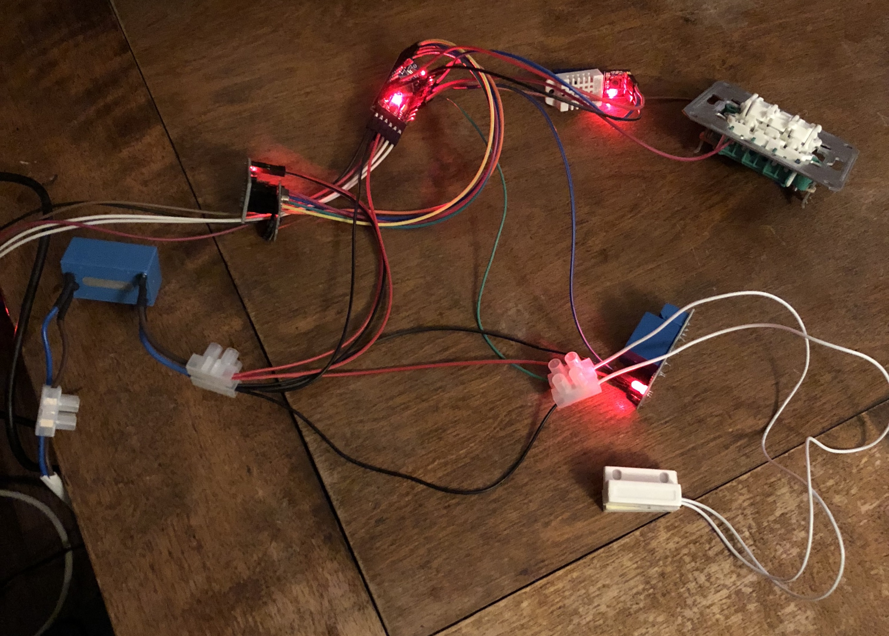
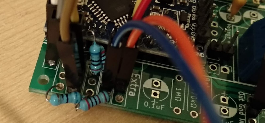
I have problem now with Home Assistant and this node. It works perfectly reading temperature, humidity and the door status.
But with the light switch if HA goes to a state where light status is "on" but brightness is "0" it doesn't respond until I manually set the brightness to "100". I tried this with mysensors library version 2.3.1 and 2.2.0 but the behaviour is the same. My gateway version is 2.1.0
Here is the code for the node. There is nothing special on HA end. I'm running hass.io latest version 0.84.6 and lovelace GUI. Sorry for the comments in the code, they are part english and part finnish :)
Just this issue to solve and one package from China and I'll get the power supplys and nodes ready. Then pretty soon I'll have 10 mysensors nodes running! I already started with some Sonoff's in the middle froor, four now installed and one waiting for a suitable application.
/*
* NODE ID: 2
* Tämä on alasisäeteisen node jossa on:
* - DHT22 -> lämpö ja kosteus
* - Releohjaus sisäeteisen valoille (kytkin+rele)
* - Ovitunnistin (hall-anturi)
* Kytkennät:
* - 5=DHT22
* - 4=Releohjaus
* - 3=Yläkerran valokytkin
* - 6=Alakerran valokytkin
* - 2=Ovitunnistin
*/
// Enable debug prints
//#define MY_DEBUG
// Noden ID (oltava kaikissa eri!!)
#define MY_NODE_ID 2
// Enable and select radio type attached
#define MY_RADIO_RF24
//#define MY_RADIO_RFM69
#define MY_REPEATER_FEATURE
#include <SPI.h>
#include <MySensors.h>
#include <Bounce2.h>
#include <DHT.h>
#include <SimpleTimer.h>
#define DOOR_PIN 2 // Ovikytkin
#define BUTTON_PIN 3 // Yläkerran valokytkin
#define BUTTON_PIN_2 6 // Alakerran valokytkin
#define RELAY_PIN 4 // Rele (valo)
#define DHT_DATA_PIN 5 // Lämpötila-anturi DHT22
#define CHILD_ID_LIGHT 1
#define CHILD_ID_HUM 2
#define CHILD_ID_TEMP 3
#define CHILD_ID_DOOR 4
#define LIGHT_OFF 0
#define LIGHT_ON 1
#define RELAY_ON 0
#define RELAY_OFF 1
#define DOOR_CLOSED 0
#define DOOR_OPEN 1
#define SENSOR_TEMP_OFFSET 0 // DHT22 lämpötilan offsetti
#define SN "kellari_sisaeteinen"
#define SV "1.2"
// Force sending an update of the temperature after n sensor reads, so a controller showing the
// timestamp of the last update doesn't show something like 3 hours in the unlikely case, that
// the value didn't change since;
// i.e. the sensor would force sending an update every UPDATE_INTERVAL*FORCE_UPDATE_N_READS [ms]
static const uint8_t FORCE_UPDATE_N_READS = 10;
float lastTemp;
float lastHum;
uint8_t nNoUpdatesTemp;
uint8_t nNoUpdatesHum;
bool metric = true;
int16_t last_state = LIGHT_OFF;
int16_t last_dim = 0;
// Yläkerran valokytkimen luku
Bounce debouncer = Bounce();
// Alakerran valokytkimen luku
Bounce debouncer_2 = Bounce();
// Ovikytkimen luku
Bounce ovidebouncer = Bounce();
// Lämpötila-anturin oliot
DHT dht;
SimpleTimer timer;
MyMessage light_msg( CHILD_ID_LIGHT, V_STATUS );
MyMessage dimmer_msg( CHILD_ID_LIGHT, V_PERCENTAGE );
MyMessage msgHum(CHILD_ID_HUM, V_HUM);
MyMessage msgTemp(CHILD_ID_TEMP, V_TEMP);
MyMessage msgOvi(CHILD_ID_DOOR, V_TRIPPED);
void setup()
{
dht.setup(DHT_DATA_PIN); // set data pin of DHT sensor
// Sleep for the time of the minimum sampling period to give the sensor time to power up
// (otherwise, timeout errors might occure for the first reading)
sleep(dht.getMinimumSamplingPeriod());
update_light();
//Serial.println( "Node ready to receive messages..." );
// Setup the buttons
pinMode(BUTTON_PIN,INPUT);
pinMode(BUTTON_PIN_2,INPUT);
// Activate internal pull-up
digitalWrite(BUTTON_PIN,HIGH);
digitalWrite(BUTTON_PIN_2,HIGH);
// Make sure relays are off when starting up
digitalWrite(RELAY_PIN, RELAY_OFF);
// Then set relay pins in output mode
pinMode(RELAY_PIN, OUTPUT);
// Yläkerran valokytkin
debouncer.attach(BUTTON_PIN, INPUT_PULLUP);
debouncer.interval(25);
// Alakerran valokytkin
debouncer_2.attach(BUTTON_PIN_2, INPUT_PULLUP);
debouncer_2.interval(25);
// Ovikytkin
ovidebouncer.attach(DOOR_PIN, INPUT_PULLUP);
ovidebouncer.interval(25);
// Timer lämpötila-anturin lukemista varten (millisekunteja) eli luetaan 1min välein
timer.setInterval(60000, lampotilaLuku);
}
void loop()
{
//In MySensors2.x, first message must come from within loop()
static bool first_message_sent = false;
if ( first_message_sent == false )
{
//Serial.println( "Sending initial state..." );
send_dimmer_message();
send_status_message();
lampotilaLuku();
send(msgOvi.set(DOOR_CLOSED));
first_message_sent = true;
}
debouncer.update(); // Update the Bounce instance (yläkerran valokytkin)
// Laskevan reunan tunnistus (yläkerran valokytkin)
if ( debouncer.fell() )
{
//Serial.println( "Laskeva reuna" );
nappiPainettu(); // Valon ohjaus
}
// Nousevan reunan tunnistus (yläkerran valokytkin)
if ( debouncer.rose() )
{
//Serial.println( "Nouseva reuna" );
nappiPainettu(); // Valon ohjaus
}
debouncer_2.update(); // Update the Bounce instance (alakerran valokytkin)
// Laskevan reunan tunnistus (alakerran valokytkin)
if ( debouncer_2.fell() )
{
//Serial.println( "Laskeva reuna" );
nappiPainettu(); // Valon ohjaus
}
// Nousevan reunan tunnistus (alakerran valokytkin)
if ( debouncer_2.rose() )
{
//Serial.println( "Nouseva reuna" );
nappiPainettu(); // Valon ohjaus
}
// Ovitunnistimen luku
if (ovidebouncer.update())
{
// Get the update value.
int value = ovidebouncer.read();
// Send in the new value.
//Serial.println( "Oven status muuttui" );
send(msgOvi.set(value==HIGH ? 1 : 0));
}
// Lämpötila-anturin timer pyörii..
timer.run();
}
void presentation()
{
// Send the sketch version information to the gateway
sendSketchInfo( SN, SV );
present( CHILD_ID_LIGHT, S_DIMMER );
present(CHILD_ID_HUM, S_HUM);
present(CHILD_ID_TEMP, S_TEMP);
present(CHILD_ID_DOOR, S_DOOR);
metric = true; // Lämpötila-anturi
}
// Vastaanotetaan HA:lta komentoja
void receive(const MyMessage &message)
{
//When receiving a V_STATUS command, switch the light between OFF
//and the last received dimmer value
// Tämä on ON/OFF viesti HA:lta
if ( message.type == V_STATUS )
{
//Serial.println( "V_STATUS command received..." );
int lstate = message.getInt();
if (( lstate < 0 ) || ( lstate > 1 )) {
//Serial.println( "V_STATUS data invalid (should be 0/1)" );
return;
}
last_state = lstate;
//If last dimmer state is zero, set dimmer to 100
if (( last_state == LIGHT_ON ) && ( last_dim == 0 ))
{
last_dim=100;
}
//Update constroller status
send_status_message();
}
// Tämä on himmennys viesti HA:lta
else if ( message.type == V_PERCENTAGE )
{
//Serial.println( "V_PERCENTAGE command received..." );
int dim_value = constrain( message.getInt(), 0, 100 );
if ( dim_value == 0 ) {
last_state = LIGHT_OFF;
//Update constroller with dimmer value & status
send_dimmer_message();
send_status_message();
}
else
{
last_state = LIGHT_ON;
last_dim = dim_value;
//Update constroller with dimmer value
send_dimmer_message();
}
}
else
{
//Serial.println( "Invalid command received..." );
return;
}
//Here you set the actual light state/level
update_light();
}
// Releen ohjaus statuksen perusteella
void update_light()
{
if ( last_state == LIGHT_OFF )
{
//Serial.println( "Light state: OFF" );
digitalWrite(RELAY_PIN, RELAY_OFF);
}
else
{
//Serial.print( "Light state: ON, Level: " );
//Serial.println( last_dim );
digitalWrite(RELAY_PIN, RELAY_ON);
}
}
// Lähetetään HA:lle dimmer arvo
void send_dimmer_message()
{
send( dimmer_msg.set( last_dim ) );
}
// Lähetetään HA:lle valon status (ON/OFF)
void send_status_message()
{
if ( last_state == LIGHT_OFF ) {
send( light_msg.set( (int16_t)0) );
} else {
send( light_msg.set( (int16_t)1) );
}
}
// Luetaan DHT22 arvot
void lampotilaLuku()
{
// Force reading sensor, so it works also after sleep()
dht.readSensor(true);
// Get temperature from DHT library
float temperature = dht.getTemperature();
if (isnan(temperature)) {
//Serial.println("Failed reading temperature from DHT!");
} else if (temperature != lastTemp || nNoUpdatesTemp == FORCE_UPDATE_N_READS) {
// Only send temperature if it changed since the last measurement or if we didn't send an update for n times
lastTemp = temperature;
if (!metric) {
temperature = dht.toFahrenheit(temperature);
}
// Reset no updates counter
nNoUpdatesTemp = 0;
temperature += SENSOR_TEMP_OFFSET;
send(msgTemp.set(temperature, 1));
#ifdef MY_DEBUG
//Serial.print("T: ");
//Serial.println(temperature);
#endif
} else {
// Increase no update counter if the temperature stayed the same
nNoUpdatesTemp++;
}
// Get humidity from DHT library
float humidity = dht.getHumidity();
if (isnan(humidity)) {
//Serial.println("Failed reading humidity from DHT");
} else if (humidity != lastHum || nNoUpdatesHum == FORCE_UPDATE_N_READS) {
// Only send humidity if it changed since the last measurement or if we didn't send an update for n times
lastHum = humidity;
// Reset no updates counter
nNoUpdatesHum = 0;
send(msgHum.set(humidity, 1));
#ifdef MY_DEBUG
//Serial.print("H: ");
//Serial.println(humidity);
#endif
} else {
// Increase no update counter if the humidity stayed the same
nNoUpdatesHum++;
}
}
// Napin painon jälkeen valon ohjaus ja statuksen päivitys
void nappiPainettu()
{
if (last_state == LIGHT_ON)
{
//Serial.println( "Valo OFF napista" );
last_state = LIGHT_OFF;
last_dim=0;
update_light(); // Releen toggle
}
else
{
//Serial.println( "Valo ON napista" );
last_state = LIGHT_ON;
last_dim=100;
update_light(); // Releen toggle
}
//Serial.println( "Lahetetaan HA:lle uusi status" );
send_status_message(); // Lähetä HA:lle uusi status (ON/OFF)
send_dimmer_message(); // Lähetä HA:lle uusi dim arvo (0/100)
}
Here are parts concerning from configuration.yaml file:
# Mysensors serial gateway config
mysensors:
gateways:
- device: '/dev/ttyACM0'
baud_rate: 115200
persistence_file: '/config/mysensors.json'
optimistic: false
persistence: true
version: 2.0