Increasing range of 8MHz ATMEGA328P with NRF24L01
-
Hi there,
Recently I designed a PCB as a PIR Motion Sensor Board for my home automation project. The aim was to mount a couple of these around the house on the ceiling so that the lights in my house could be motion-activated/deactivated (I already have wired up a bunch of relays to my mains using ESPHome, Home Assistant).
However, after soldering everything up I was unable to get the node to communicate with the gateway at all. After some head-banging, I finally changed the NRF24L01 module from the short one (image 1) to the longer one with the "high power" and PA LNA capabilities (image 2) and bingo the gateway started receiving messages from my node.
However, the range is severely limited (to about a few meters) and once I move the gateway back to its original spot (Raspberry Pi) the comms fail again...
I have created various end nodes using Arduino Nanos (5V) with the "small" NRF24L01 boards (even my gateway) and they all work great, even at much longer ranges.
Specs:
Microcontroller: ATMEGA328P
Frequency: 8MHz
Voltage: 3.3VCode
//Code description was removed for readability
// Enable debug prints
 #define MY_DEBUG
 #define MY_BAUD_RATE 9600

// Enable and select radio type attached
#define MY_RADIO_RF24
#define MY_RF24_PA_LEVEL RF24_PA_LOW
//#define MY_RADIO_NRF5_ESB
//#define MY_RADIO_RFM69
//#define MY_RADIO_RFM95

#include <MySensors.h>

uint32_t SLEEP_TIME = 1000; // Sleep time between reports (in milliseconds)
#define DIGITAL_INPUT_SENSOR 3   // The digital input you attached your motion sensor.  (Only 2 and 3 generates interrupt!)
#define LDR_SENSOR_1 A0
#define LDR_SENSOR_2 A1
#define BATTERY_SENSE_PIN A2

int oldBatteryPcnt = 0;

// Initialize motion message
MyMessage motion(0, V_TRIPPED);
MyMessage firstLDR(1, V_LIGHT_LEVEL);
MyMessage secondLDR(2, V_LIGHT_LEVEL);

void setup()
{
  pinMode(DIGITAL_INPUT_SENSOR, INPUT);
  pinMode(LDR_SENSOR_1, INPUT_PULLUP);
  pinMode(LDR_SENSOR_2, INPUT_PULLUP);
}

void presentation()
{
  sendSketchInfo("Motion Sensor", "1.0");

  present(0, S_MOTION);
  present(1, S_LIGHT_LEVEL);
  present(2, S_LIGHT_LEVEL);
}

void loop()
{
  bool tripped = digitalRead(DIGITAL_INPUT_SENSOR) == HIGH;
  int light1 = analogRead(LDR_SENSOR_1);
  int light2 = analogRead(LDR_SENSOR_2);
  int sensorValue = analogRead(BATTERY_SENSE_PIN);
  int batteryPerc = (sensorValue * 10) / 10230 * 110;

  Serial.print("Motion: "); Serial.println(tripped);
  Serial.print("LDR 1: "); Serial.println(light1);
  Serial.print("LDR 2: "); Serial.println(light2);
  Serial.print("Battery Sensor Value: "); Serial.println(sensorValue);
  Serial.print("Battery Percentage: "); Serial.println(batteryPerc);

  send(motion.set(tripped?"1":"0"));  // Send tripped value to gw
  send(firstLDR.set(light1));
  send(secondLDR.set(light2));

  if(oldBatteryPcnt != batteryPerc){
    sendBatteryLevel(batteryPerc);
    oldBatteryPcnt = batteryPerc;
  }

	// Sleep until interrupt comes in on motion sensor. Send update every ten minutes.
	sleep(digitalPinToInterrupt(DIGITAL_INPUT_SENSOR), CHANGE, SLEEP_TIME);
}
What I have tried doing
- The wiring is definitely correct as I checked continuity on all the 328P's and NRF24L01's pins
- Cleared EEPROM according to this
- Swapped around "small" NRF24L01 modules with end nodes that are confirmed to be working
- Added 47uF cap across the NRF24L01's supply pins
- Added a 22AWG wire to connect the NRF24L01's supply pins directly to the voltage input (to rule out resistance of the traces)
- Defined
#define MY_RF24_PA_LEVEL RF24_PA_LOW
What I suspect is the problem
Given that all my other end nodes work fine with the "small" NRF24L01, I suspect it is:- 3.3V logic level (although the NRF24L01 should be 3.3V logic level as well)
- 8MHz frequency (I observed that the "small" NRF24L01 modules have a 16MHz crystal)
- My board layout (notably traces being too thin / too many crisscrossing signal paths, vias etc)
I have attached the .brd and .sch files (EAGLE) here for those who would be willing to take a look at them.
I would be most appreciative of any advice, especially from anyone who has tried their hand at a similar setup as mine.
Thanks!
-
Hi, I tested the setup with both a lab bench power supply as well as a BL8530 boost converter IC to boost two AA batteries to 3.3V.
-
Frequency and voltage of an Atmega does not effect radio quality of a NFR24 in any way (if it is stable and well decoupled voltage).
@Ethan-Chua said in Increasing range of 8MHz ATMEGA328P with NRF24L01:
Defined #define MY_RF24_PA_LEVEL RF24_PA_LOW
That's the opposite of what you want to achieve.
It either problem with cheap nrf modules, or your pcb design. By the way you have big problems with the latter:
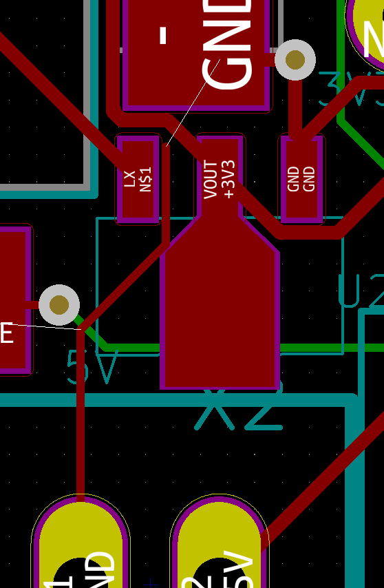
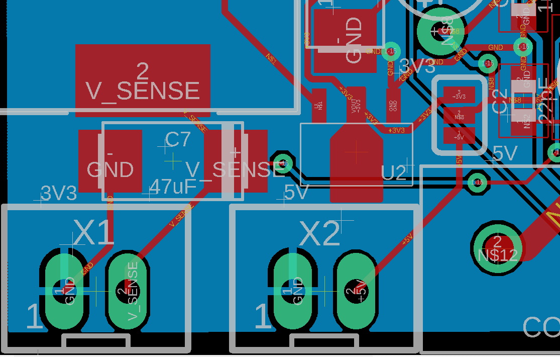
Your PCB doesn't have separated ground plane, and even that thin piece of ground track that tries to get to the point isn't connected. And what even worse it almost touching 3.3V out pin of BL8530. You need pay more attention to track clearance and consistency. How are you powering this board? -
You know what I did? Switched to RFM69. You know why? Because I couldn’t get the shit done with nRF24s. You don’t even know if you have real nRF or some counterfeits - that’s the real problem. You can buy HackRF One to sniff on 2.4GHz band, but that won’t tell you if your module is receiving anything.
Really, to spare you some time - give up on these. -
One error I make repeatedly when programming the 8MHz 328, is that I forget to select "Processor: Atmega328P (3.3V, 8MHz)" from the tool bar before programming. The 8MHz 328 will accept programs using the 5 V version of that processor selection, but the baud rate will be half of what you think it is. Maybe that will help you.
-
You know what I did? Switched to RFM69. You know why? Because I couldn’t get the shit done with nRF24s. You don’t even know if you have real nRF or some counterfeits - that’s the real problem. You can buy HackRF One to sniff on 2.4GHz band, but that won’t tell you if your module is receiving anything.
Really, to spare you some time - give up on these. -
@Bogusz-Jagoda well, if you buy modules for 50c including shipping, you can be sure they are counterfeit. If you buy slightly more expensive Ebyte modules, they always work. You get what you pay for.
@monte True, eByte’s are legit, afaik. But still you’re encountering some problems. 2.4Ghz band is pretty messy. 315/433/868 are still better solution (more obsolete now)… requiring larger antenna, though.
-
Frequency and voltage of an Atmega does not effect radio quality of a NFR24 in any way (if it is stable and well decoupled voltage).
@Ethan-Chua said in Increasing range of 8MHz ATMEGA328P with NRF24L01:
Defined #define MY_RF24_PA_LEVEL RF24_PA_LOW
That's the opposite of what you want to achieve.
It either problem with cheap nrf modules, or your pcb design. By the way you have big problems with the latter:
Your PCB doesn't have separated ground plane, and even that thin piece of ground track that tries to get to the point isn't connected. And what even worse it almost touching 3.3V out pin of BL8530. You need pay more attention to track clearance and consistency. How are you powering this board?@monte Hi there thanks for pointing this out. I went back to have a look at the PCB files and it turns out I messed up the .brd file while probing around which resulted in the GND wire stub.
The actual board has a GND plane on the bottom layer like so:
-
One error I make repeatedly when programming the 8MHz 328, is that I forget to select "Processor: Atmega328P (3.3V, 8MHz)" from the tool bar before programming. The 8MHz 328 will accept programs using the 5 V version of that processor selection, but the baud rate will be half of what you think it is. Maybe that will help you.
@Larson
Hi may I know what Board setup you are using? I am using the MiniCore Board "Library" and apart from the BOD fuse setting I don't see any other voltage option.
Could you share the board library you are using, worth giving it a shot to see if that helps. Thanks.
-
@Ethan-Chua The boards I'm using are cheap Pro-minis. Google for "Pro Mini 328 3V arduino" and you will find many selections. I buy mine by the 10-pack from China, but it is quicker to go to someone like SparkFun or Adafruit.
The voltage options are visible on the IDE tool bar after first selecting "Board: Arduino Pro or Pro Mini". Only then will the option "Atmege 328P (3.3V, 8MHz)" be visible for selecting. These selections drop down from the menu available after clicking on TOOL in the IDE. You might have to first go to Boards Manager to download files for these boards, though I think these files came on my IDE.
My IDE is Arduino 1.8.12. The libraries I am using are:
#include <LowPower.h>
#include <SBWire.h> //Wire.h was giving me some problems so I switched,
#include <MechaQMC5883_SBWire.h> //for a magnetometer
#include <Arduino.h>
#include <avr/io.h>
#include <avr/interrupt.h>The Pro Mini drives an ESP8266 to send water meter data to the web. I use a magnetometer wired to the Pro Mini to sense the spinning magnet in the meter. I know I've got redundant CPU's but the power-hungry ESP sleeps most of the time while the low-power Pro Mini quietly collects the data.
Hope it helps.
-
@Larson
Hi may I know what Board setup you are using? I am using the MiniCore Board "Library" and apart from the BOD fuse setting I don't see any other voltage option.
Could you share the board library you are using, worth giving it a shot to see if that helps. Thanks.
@Ethan-Chua In Arduino IDE, go to "Tools" -> "minicore" and select the board you are using from the drop down menu. Then underneath 'Tools' menu you will see all options for the bootloader. You should select these values to match your requirements.
Hello! It looks like you're interested in this conversation, but you don't have an account yet.
Getting fed up of having to scroll through the same posts each visit? When you register for an account, you'll always come back to exactly where you were before, and choose to be notified of new replies (either via email, or push notification). You'll also be able to save bookmarks and upvote posts to show your appreciation to other community members.
With your input, this post could be even better 💗
Register Login