6 Way wall touch switch
-
Hello,
This weekend I've been busy with a prototype for a touch wall switch.
So far is going pretty well and everything seems to work.
I still need to integrate it with MySensors, but I hope this will be the easiest part.
The only problem I found is with the sensitivity of the touch sensors when connected to external power.
It works perfectly when using USB power, but not quite right then using AC power.Here's how it looks so far. Remember this is just a proof of concept and many things where just do as I go and probably will be a better way to do it.
Any suggestions / comments will be greatly appreciated.
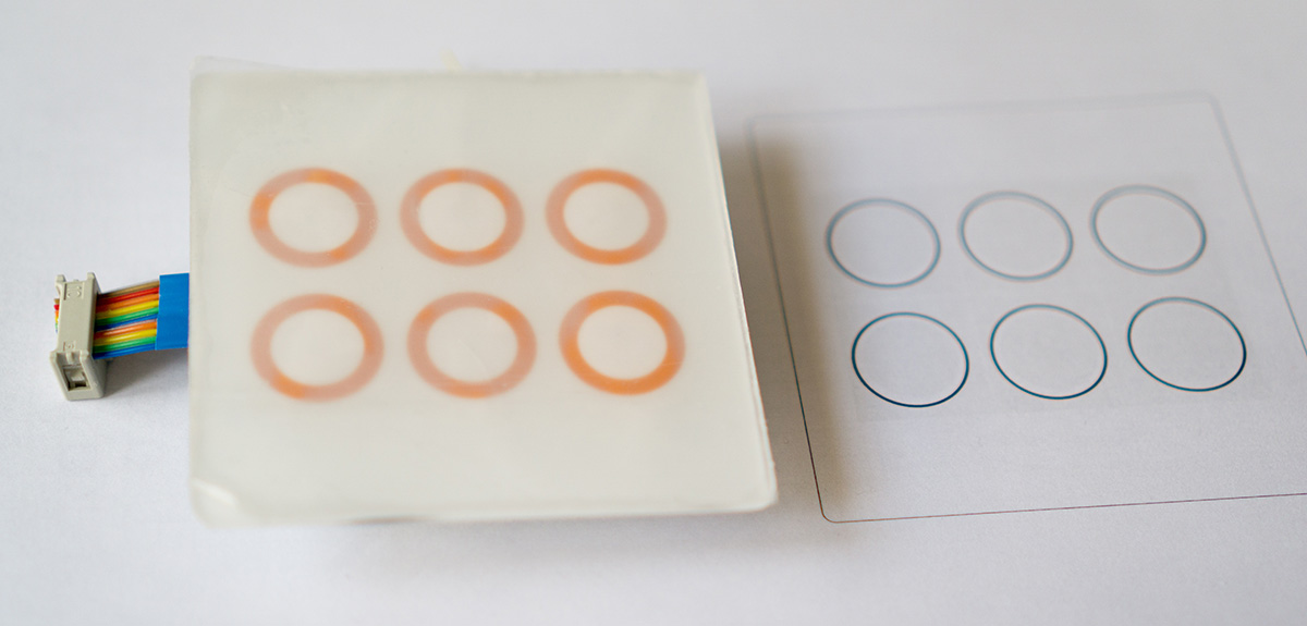
This is the front plate made with a 2mm methacrylate plastic, with a printed paper behind.
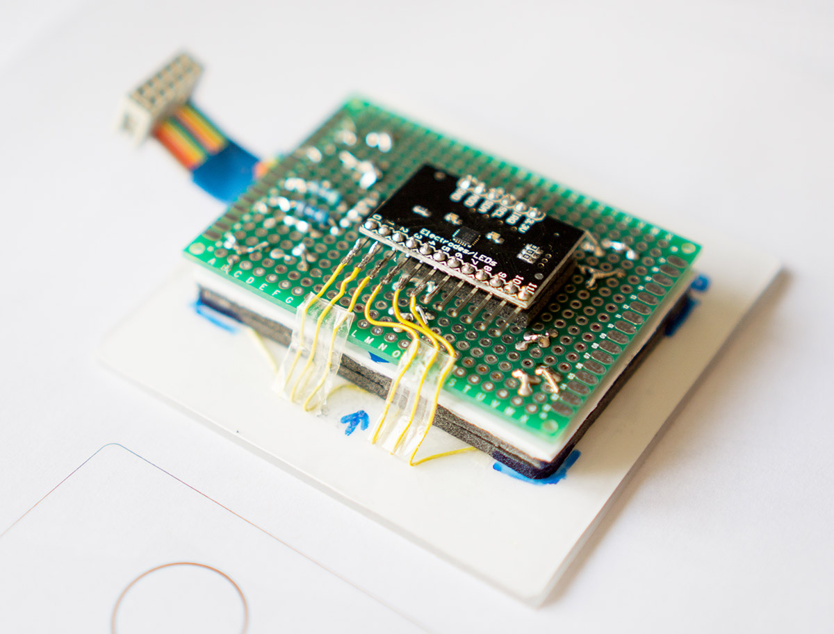
This is the back side with the touch controller
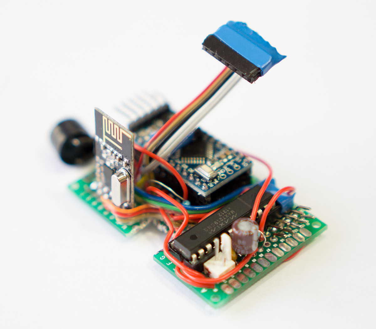
And this is the actual node with the led driver and the buzzer
And this is how it works for now
c100b.mp4 -
I love to hear the details.. Have been waiting for some original projects.
-
This is a rough integration of the code with MySensors.
It sends messages back and forth, so if a button is touched it turns on the corresponding device on the controller and if the switch is turned on the controller, the touch leds are updated accordingly#include "mpr121.h" #include <Wire.h> #include "LedControlMS.h" #include <MySensor.h> #include <SPI.h> #include <MyBuffer.h> #define CHILD_ID1 1 // first child #define CHILD_NUM 6 // number of switches //define working pins #define BUZZER 7 // buzzer pin #define DIN 6 // pin 6 is connected to the DataIn #define CLK 4 // pin 4 is connected to the CLK #define LOD 8 // pin 8 is connected to LOAD #define IRQ 3 // irq pin for touch control #define BAKLIT 5 // pin PWM for backlight leds // ********* MyBuffer *********************************************************** MyBuffer buffer; // define a new buffer long previousMillis = 0; // will store last time buffer was processed long interval = 1000; // interval at which to check buffer // ****************************************************************************** MySensor gw; //define a new led control LedControl lc=LedControl(DIN,CLK,LOD,1); //int irqpin = 3; // Digital pin IRQ boolean touchStates[12]; //to keep track of the previous touch states boolean touchMemory[12]; //to keep track of the touch switch states // correspondence between touch and led pins int mapping[2][6]={{0,1,2,3,4,5} // touch pins ,{1,0,2,5,4,3}}; // led pins int sound = 500; int touchDelay=500; void setup(){ // init LED backlight pinMode(BAKLIT, OUTPUT); analogWrite(BAKLIT, 5); pinMode(IRQ, INPUT); digitalWrite(IRQ, HIGH); //enable pullup resistor Wire.begin(); pinMode(BUZZER, OUTPUT); for (int i=0; i < 12; i++){ touchMemory[i]=false; } mpr121_setup(); //initialize MAX72XX lc.shutdown(0,false); lc.setIntensity(0,15); lc.clearDisplay(0); gw.begin(incomingMessage, AUTO); //do not make relay node gw.sendSketchInfo("WallTouch", "1.0"); for (int i=0; i<CHILD_NUM;i++) { gw.present(CHILD_ID1+i, S_LIGHT); // Set touch button leds to last known state (using eeprom storage) touchMemory[i] = gw.loadState(i)?true:false; setLed(mapping[1][i],touchMemory[i]); } } void loop(){ gw.process(); //watch for touch events readTouchInputs(); //check for buffer items once in a while checkTime(); } void checkTime(){ unsigned long currentMillis = millis(); if(currentMillis - previousMillis > interval) { previousMillis = currentMillis; processBuffer(); } } void incomingMessage(const MyMessage &message) { buffer.push(message.sensor,message.type,message.getString()); } //gets message from buffer if exists void processBuffer(){ if(!buffer.isEmpty()){ String msg=buffer.pop(); int mIndex = msg.indexOf(';'); int secondmIndex = msg.indexOf(';', mIndex+1); String firstValue = msg.substring(0, mIndex); String secondValue = msg.substring(mIndex+1, secondmIndex); String thirdValue = msg.substring(secondmIndex+1); int sensor = firstValue.toInt(); int type = secondValue.toInt(); String data = thirdValue; Serial.println(" >> Process MSG: s:"+ firstValue +", t:"+secondValue+", d:"+thirdValue); processMsg(sensor, type, data); } } //process message from queue void processMsg(int sensor, int type, String data){ boolean msg; switch(type){ case V_LIGHT: //comando para 1 rele msg=data.toInt()?1:0; // Store state in eeprom gw.saveState(sensor, msg); // Write some debug info Serial.print("--> Incoming change for child:"); Serial.print(sensor-1); Serial.print(", New status: "); Serial.println(msg); setTouchButton(sensor-1); break; } } void setTouchButton(int pressed){ MyMessage msg(CHILD_ID1+pressed,V_LIGHT); Serial.print("pin "); Serial.print(pressed); Serial.print(" was just touched"); Serial.print(", turning: "); touchMemory[pressed]=touchMemory[pressed]?false:true; gw.saveState(pressed, touchMemory[pressed]); Serial.println(touchMemory[pressed]?"ON":"OFF"); setLed(mapping[1][pressed],touchMemory[pressed]?true:false); gw.send(msg.set(touchMemory[pressed] ? 1 : 0)); touchSound(); } void setLed(int led, boolean lit){ lc.setLed(0,0,led,lit); } void readTouchInputs(){ if(!checkInterrupt()){ //read the touch state from the MPR121 Wire.requestFrom(0x5A,2); byte LSB = Wire.read(); byte MSB = Wire.read(); uint16_t touched = ((MSB << 8) | LSB); //16bits that make up the touch states for (int i=0; i < 12; i++){ // Check what electrodes were pressed if(touched & (1<<i)){ if(touchStates[i] == 0){ //pin i was just touched setTouchButton(i); delay(touchDelay); }else if(touchStates[i] == 1){ //pin i is still being touched } touchStates[i] = 1; }else{ /* if(touchStates[i] == 1){ Serial.print("pin "); Serial.print(i); Serial.println(" is no longer being touched"); //pin i is no longer being touched }*/ touchStates[i] = 0; } } } } void touchSound(){ tone(BUZZER, sound, 3); } void mpr121_setup(void){ set_register(0x5A, ELE_CFG, 0x00); // Section A - Controls filtering when data is > baseline. set_register(0x5A, MHD_R, 0x01); set_register(0x5A, NHD_R, 0x01); set_register(0x5A, NCL_R, 0x00); set_register(0x5A, FDL_R, 0x00); // Section B - Controls filtering when data is < baseline. set_register(0x5A, MHD_F, 0x01); set_register(0x5A, NHD_F, 0x01); set_register(0x5A, NCL_F, 0xFF); set_register(0x5A, FDL_F, 0x02); // Section C - Sets touch and release thresholds for each electrode set_register(0x5A, ELE0_T, TOU_THRESH); set_register(0x5A, ELE0_R, REL_THRESH); set_register(0x5A, ELE1_T, TOU_THRESH); set_register(0x5A, ELE1_R, REL_THRESH); set_register(0x5A, ELE2_T, TOU_THRESH); set_register(0x5A, ELE2_R, REL_THRESH); set_register(0x5A, ELE3_T, TOU_THRESH); set_register(0x5A, ELE3_R, REL_THRESH); set_register(0x5A, ELE4_T, TOU_THRESH); set_register(0x5A, ELE4_R, REL_THRESH); set_register(0x5A, ELE5_T, TOU_THRESH); set_register(0x5A, ELE5_R, REL_THRESH); /* set_register(0x5A, ELE6_T, TOU_THRESH); set_register(0x5A, ELE6_R, REL_THRESH); set_register(0x5A, ELE7_T, TOU_THRESH); set_register(0x5A, ELE7_R, REL_THRESH); set_register(0x5A, ELE8_T, TOU_THRESH); set_register(0x5A, ELE8_R, REL_THRESH); set_register(0x5A, ELE9_T, TOU_THRESH); set_register(0x5A, ELE9_R, REL_THRESH); set_register(0x5A, ELE10_T, TOU_THRESH); set_register(0x5A, ELE10_R, REL_THRESH); set_register(0x5A, ELE11_T, TOU_THRESH); set_register(0x5A, ELE11_R, REL_THRESH); */ // Section D // Set the Filter Configuration // Set ESI2 set_register(0x5A, FIL_CFG, 0x12); //12 mas menos //set_register(0x5A, FIL_CFG, 0x24); //segundo filtro // set_register(0x5A, 0x5C, 0x28); // primer filtro (mio) //ajuste de la corrente de carga de cada pin /* set_register(0x5A, 0x5F, CDC_sensor[0]); //el 0 set_register(0x5A, 0x60, CDC_sensor[1]); //el 1 set_register(0x5A, 0x61, CDC_sensor[2]); //el 2 set_register(0x5A, 0x62, CDC_sensor[3]); //el 3 set_register(0x5A, 0x63, CDC_sensor[4]); //el 4 set_register(0x5A, 0x64, CDC_sensor[5]); //el 5 */ // Section E // Electrode Configuration // Set ELE_CFG to 0x00 to return to standby mode set_register(0x5A, ELE_CFG, 0x0C); // Enables all 12 Electrodes // Section F // Enable Auto Config and auto Reconfig /*set_register(0x5A, ATO_CFG0, 0x0B); set_register(0x5A, ATO_CFGU, 0xC9); // USL = (Vdd-0.7)/vdd*256 = 0xC9 @3.3V set_register(0x5A, ATO_CFGL, 0x82); // LSL = 0.65*USL = 0x82 @3.3V set_register(0x5A, ATO_CFGT, 0xB5);*/ // Target = 0.9*USL = 0xB5 @3.3V set_register(0x5A, ELE_CFG, 0x0C); } boolean checkInterrupt(void){ return digitalRead(IRQ); } void set_register(int address, unsigned char r, unsigned char v){ Wire.beginTransmission(address); Wire.write(r); Wire.write(v); Wire.endTransmission(); } -
I got it finally installed.
This is what it looks like.I'm working on a pcb smaller version. I'll keep you posted.
-
@ferpando said:
LedControlMS
Can you share to me your project, pls?
How to cônnect 6 buttons with 6 leds?
sorry i newbie.
Thanks@quocanhcgd
I'll post the project when I finish the PCB and everything is a bit more mature.
I already uploaded the sketch I used here.
I made it with a max7219 led driver but you could also use a shift register to control the leds with minimal modifications -
@quocanhcgd
I'll post the project when I finish the PCB and everything is a bit more mature.
I already uploaded the sketch I used here.
I made it with a max7219 led driver but you could also use a shift register to control the leds with minimal modifications -
Any News?
-
I also built a 6way wall switch. It does not have lights but is battery powered and very well documented. It is kind of rocket science because it has a 3d printed housing and a self etched pcb but maybe it helps anyway at least for the (very easy) source code:
-
I also built a 6way wall switch. It does not have lights but is battery powered and very well documented. It is kind of rocket science because it has a 3d printed housing and a self etched pcb but maybe it helps anyway at least for the (very easy) source code:
-
Is there a chance that you can share your full setup? I like your wall touch switch very much. :smile:
@Didi
YesI will when I have the second version ready.
This is a bit messy :-)
I'll keep you posted
Hello! It looks like you're interested in this conversation, but you don't have an account yet.
Getting fed up of having to scroll through the same posts each visit? When you register for an account, you'll always come back to exactly where you were before, and choose to be notified of new replies (either via email, or push notification). You'll also be able to save bookmarks and upvote posts to show your appreciation to other community members.
With your input, this post could be even better 💗
Register Login