Changing from serial to ethernet gateway
-
It was a bit dissapointing that when my vera 3 loses power, it also loses the info on the serial port. The ethernet gateway will avoid this I understand.
Last week I recieved my WizNet W5100.
Reading through the "build" part of this website I do have a couple of questions:
#define IP_PORT 5003 // The port you want to open-Do I need to change this , or leave it as it is? No clue if port 5003 is in use my any of my devices.
-Do I need to remove anything on my vera 3 since I "had" the serial gateway?
-The 4 arduinos which are now included and have a device number, will they still be working ,Or do i have to remove them and include them again?Thanks,
Cor -
@Corvl I just did this myself a month ago for the same reason as you. Here are some of things I noted that may help you.
Port 5003 should be fine. I just tried it and it worked but if you are concerned there is probably some software out there that can tell you which ports are free.
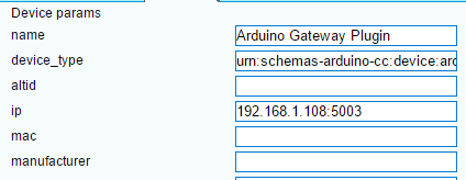
You don't need to remove anything but you will need to change the configuration in the Advanced tab to add the IP. Something like this:
All the devices should still work without having to make any changes to Vera but I had to power cycle all my devices that receive commands (relays, lights). For some reason they didn't want to receive messages but they would send them.
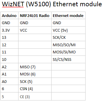
Also, my wiring pin names were a little different that what was listed on the build portion of this site. None of actual pins change just what was listed on the WizNET board.
Also note that the WizNET board needs to board needs to be supplied with 5v even though it looks like 3.3v may work.
Hope that helps.
Pete
-
Ah , cool , good to know that nothing on the vera side needs to change except for the Ip adress and port.
I will start this project in an hour or , before I do so I do have a question about what you mentioned last about the pin setup.
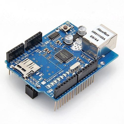
When I look at my WizNET (Ws5100) ethernet module ,i don't have pins ( SCK/CK/MISO/SO/MI.MOSI, SI/MO/SS/CS/NSS) on it , the pins are the same when I compare with my UNO.
It looks I can insert this module straight on an UNO. The plan is actually to use this module for a nano ..... I can still use this module?
But how to wire this module , The pins (names) are accactly the same as on a UNO .:sweat:
Damn , I am allready stuck , and even haven't started yet :-(
Cor
-
Ah , cool , good to know that nothing on the vera side needs to change except for the Ip adress and port.
I will start this project in an hour or , before I do so I do have a question about what you mentioned last about the pin setup.
When I look at my WizNET (Ws5100) ethernet module ,i don't have pins ( SCK/CK/MISO/SO/MI.MOSI, SI/MO/SS/CS/NSS) on it , the pins are the same when I compare with my UNO.
It looks I can insert this module straight on an UNO. The plan is actually to use this module for a nano ..... I can still use this module?
But how to wire this module , The pins (names) are accactly the same as on a UNO .:sweat:
Damn , I am allready stuck , and even haven't started yet :-(
Cor
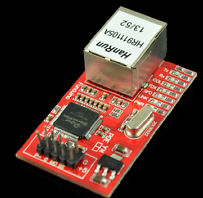
@Corvl Hmm. I'm not sure about that. I used one that looks like this:
I know that you need to use softspi for this to work correctly so that's why the pins are different. Someone else much more knowledgeable than me may know how you can connect up that sheild.
Also, one thing I forgot to mention. I believe your sensors need to be on 1.4.1 for this to work (because it uses softspi). Is that what you're currently running?
-
Aha , interesting ,
I saw that ethernetshield as well , must have been a brainfart to buy this one ;-s
I found this instructable on the internet:
http://www.instructables.com/id/Arduino-Nano-with-Ethernet-Shield/?ALLSTEPSHopefully that works , or shouldn't I even try and buy another one?:scream:
Cor
-
Ah , cool , good to know that nothing on the vera side needs to change except for the Ip adress and port.
I will start this project in an hour or , before I do so I do have a question about what you mentioned last about the pin setup.
When I look at my WizNET (Ws5100) ethernet module ,i don't have pins ( SCK/CK/MISO/SO/MI.MOSI, SI/MO/SS/CS/NSS) on it , the pins are the same when I compare with my UNO.
It looks I can insert this module straight on an UNO. The plan is actually to use this module for a nano ..... I can still use this module?
But how to wire this module , The pins (names) are accactly the same as on a UNO .:sweat:
Damn , I am allready stuck , and even haven't started yet :-(
Cor
@Corvl I am using the WizNET (Ws5100) ethernet module. Just plug it in to the Arduino like you suggested and everything will be connected properly except for the radio. That's where you have to worry about connecting it properly to the Arduino pins so that it does not use the same SCK/CK/MISO/SO/MI.MOSI as the Ethernet module, hence the use of soft spi so that you can connect the radio toA2, A1 etc. and not interfere with the Ethernet module. Also make sure that you have separate power supply for the radio since you cannot power everything from the Arduino alone.
-
@Dan-S. said:
so that it does not use the same SCK/CK/MISO/SO/MI.MOSI
Cool that it will be working , do you have any ide than how I connect the radio? Will the sketch work than, without changing a lot of the configuration?
thanks,
Cor@Corvl Just follow the directions for connecting the radio to pins 5, 6, A0,A1 and A2 is indicated in the build instructions on the my sensors home site. You can connected them directly to the top ethernet module pinouts since the pins on the module are identified as the same pins that plug into the arduino. They pass through the same connections and are identified the same as if you connected directly to the Arduino. Just make the software RF24_config.h change specified to make soft spi work
-
That was easy....... worked the first time and very well ....
I worried for nothing :-)
One question though; When all was funktioning fine I soldered a 12v DC (1A) adapter on the ground and Vin. The arduino normally started up ,but didn't work. I tried another 12vDC (2A) adapter , and exactly the same.
When I Plug the arduino Uno in my computer via USB or a USB charger via the USB-port , all works fine. Anyone has an idea why this is?
Thanks for all the help ,
Cor -
That was easy....... worked the first time and very well ....
I worried for nothing :-)
One question though; When all was funktioning fine I soldered a 12v DC (1A) adapter on the ground and Vin. The arduino normally started up ,but didn't work. I tried another 12vDC (2A) adapter , and exactly the same.
When I Plug the arduino Uno in my computer via USB or a USB charger via the USB-port , all works fine. Anyone has an idea why this is?
Thanks for all the help ,
Cor@Corvl Should work the way you described the connection. May be a problem with the onboard voltage regulator which is supposed to provide 5 volt from the 12 volt input. When you connect USB you are inputing 5 volts. I would recommend you try connecting the adaptor via the UNO power input connector with a proper power plug rather than soldering it. I have a 9 volt adapter connected that way to my UNO and it works fine.
-
aha , cheap chinese clone.:astonished:
It is a nano , doesn't have a power input. also the ethernet adapter has no seperate power connector.
Vinn and ground should work , and I didn't do it wrong..... wierd ..... thankfully it is working via the USB connector . I will leave it as it is in that case.
-
@petewill I appreciate the documentation of your experience. You have answered many of my questions. I am curious about what arduino you used for your gateway specifically how you powered it and the radio?
Also I have seen a couple of your videos where you talk about changing the channel in the my config.h file to possibly improve reception, if this is done on the gateway must you also re-upload to all your sensors?
Thanks
@jlieffort
Hi Jim,
Part of this is in response to your questions posted on YouTube. I powered as many devices as I could from a phone charger directly (W5100 and Pro Mini) I also believe I powered the radio from the 5v phone charger but with a 3.3v regulator and capacitors in between.Yes, if you change the channel in myconfig.h you will have to reprogram all your sensors :(
Now for the YouTube stuff. You said you have myscontroller receiving messages from the Ethernet gateway. Does it also send them to the gateway? Are you on UI7?
-
Yes found this today so make more sense here. I just got the MYSController program today, so learning it. I'm using UI7. When I go into inclusion mode, I get message 1, then message 0. I am trying to add a sensor that I know works, the same way I've done many times with my serial GW. I'm kinda stuck. Soft SPI enabled in MyConfig.h,. I can see the device when I use "advanced IP scanning" tool, with the MAC that's is in the sketch and the right IP (10.0.0.50 Port 5003). Have swapped out everything except the Ethernet board 5100, exactly like the one you show above. Using a genuine Nano now. Long range NRF24 radio with antenna. Help appreciated :)
-
@jlieffort
Hi Jim,
Part of this is in response to your questions posted on YouTube. I powered as many devices as I could from a phone charger directly (W5100 and Pro Mini) I also believe I powered the radio from the 5v phone charger but with a 3.3v regulator and capacitors in between.Yes, if you change the channel in myconfig.h you will have to reprogram all your sensors :(
Now for the YouTube stuff. You said you have myscontroller receiving messages from the Ethernet gateway. Does it also send them to the gateway? Are you on UI7?
-
@jlieffort Hmm. Were you able to get any sensors to report via MYSController? They should start showing up without having to do anything except configure it to use the Ethernet gateway. You may also want to try switching out the long range antenna for a standard one. Those have caused issues for me.
@petewill Success well very close. Your suggestion right on.
I swapped out a long range antennae for a different long range, and I now have everything reporting and I'm able to control everything. Yeah !!! Only thing I'm having an issue with now is I can't include any new sensors? Any ideas? I have been letting it automatically add id and I just hit 200 the other day.........
-
@jlieffort said:
I just hit 200 the other day.........
You have 200 separate nodes in your house!? WOW! What are they all for?
Only thing I'm having an issue with now is I can't include any new sensors?
Where are things going wrong? Can you press the include button in Vera to have it start looking for new nodes but they just aren't recognized? Have you totally rebooted (unplugged power) Vera since adding the Ethernet controller? If you have MYSController connected make sure you shut it off when you are trying to include sensors as it could conflict.
If that doesn't help, please describe the process you are using and were it stops working in as much detail as you can.
@petewill probably using the wrong word "Node" it assigns a number and because I've been messing around with it so much, it's up to 200, I really only have about 15 my sensor devices.
When using include mode it looks like they are seen on the Myscontroller, but nothing reports back to the Vera. So I will try your idea without using Myscontroller.
Also some of my motion sensors and a home made light sensor are not communicating. All my relays are working, and some of the motion sensors close to the Ethernet gw are still working. My typical build was using a nano clone and powering the radio right off the 3.3v. Some weeks ago on my relays I added 3.3v regulated power. That seemed to make much more reliable than the clone 3.3. alone. Today I will add regulators to some that are still without.
I was also able to change my comcast modem to use a channel that was not right on top of the the mios network.
If I can get the include button to work I'm Golden, then I'm sure on the the next issue. As always you've been a great help thank you. Jim
Hello! It looks like you're interested in this conversation, but you don't have an account yet.
Getting fed up of having to scroll through the same posts each visit? When you register for an account, you'll always come back to exactly where you were before, and choose to be notified of new replies (either via email, or push notification). You'll also be able to save bookmarks and upvote posts to show your appreciation to other community members.
With your input, this post could be even better 💗
Register Login