How low can arduino can go?
-
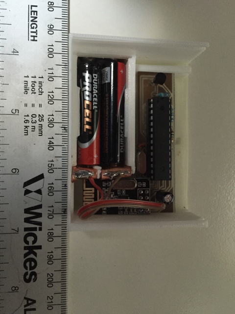
My Temperature sensor, using Dallas, and radio, has been running for more than 2 months and show no sign of going flat... In fact the battery monitoring hasn't reported a single drop in power yet!!!
If you really need low power like this, then you should think about etching a PCB with your circuit.
-
is your measuring device capable of measuring low currents below 1mA? And what have you done software wise, for lowering power usage of the arduino?
@tbowmo said:
is your measuring device capable of measuring low currents below 1mA?
Yes, it can
And what have you done software wise, for lowering power usage of the arduino?
following is my result (after cut voltage regulator, cut led, put RF radio, @ 1MHz):
- running below code : 1,89mA
void setup(){ } void loop(){ }- running below code : 2,07mA
void setup(){ Serial.begin(4800); Serial.println("Setup"); } void loop(){ Serial.println("Loop"); delay(1000); }- running below code : 2,26mA
#include <SPI.h> #include <MySensor.h> MySensor gw; void setup() { gw.begin(); Serial.print("Setup"); } void loop() { Serial.print("Loop"); gw.sleep(1000*8); }- running below code : 3,86mA
#include <SPI.h>
#include <MySensor.h>

MySensor gw;

void setup()
{
  gw.begin();
  Serial.print("Setup");
}

void loop()
{
  gw.powerDown();
}
All the power consumption taken after one minute after power is on.
-
@funky81 said:i
nning below code : 3,86mA
i have a setup with temp/humidity/light with mini pro 8mhz 3.3 v and take around 120 uA in sleep mode :)
-
-
If you have a problem with your project (in this case you can't get the power consumption down to microamps) it's maybe a good idea to start with a bare minimum setup. In this case an Arduino Pro Mini, a regulated power supply and a sketch that's puts the Arduino to sleep. So for now you better focus on sleeping the Pro Mini and bring current consumption down to a couple of microamps before trying anything else.
First you need to understand what these power savings are all about. This site (Nick Gammon) is all you need to know about power saving techniques for microprocessors (a must read):
http://www.gammon.com.au/forum/?id=11497Read it all, do some of the examples yourself and above all try to understand what's happening.
After that start with your basic setup to put the Arduino to sleep. This is how I do it:
Arduino Pro Mini: use the 3.3v version. Remove the power led because it's useless and it's still using a couple of milliamps. I lift it off the board by using a small watchmaker screwdriver. Try to get it between the bottom side of the led and the pcb and use some force to lift it from the board. You could also cut one of the connections from the led to the board. For now don't remove the voltage regulator (more about this later).
For the power supply I use a 3.3 volt LDO voltage regulator. In this case the HT7333-A (TO-92 package). I know there are a lot more LDO voltage regulators to choose from, but I have good results with this LDO. Search Ebay for it. Price is about $4 for 20 pieces. They have an ultra low quiescent current of only 4 microamps. According to the datasheet you need a 10 uF cap across Vin and GND and Vout and GND so use them. Find and read the datasheet to find out how to connect it.
I’m using 3 AAA batteries (alkaline) to power the voltage regulator. Later on you can try other options (step-up, step-down, other regulators and so on) but for now stick with the setup as described above.
Finally use the sketch below to put the Mini to sleep and check with your multimeter the current consumption. In this case I measured 38 uA with the voltage regulator in place (Voltcraft VC170 digital multimeter). After removing the voltage regulator I measured a current of only 3uA. Be aware that measuring very low currents are influenced by burden voltage (this is a nice video about burden voltage https://www.youtube.com/watch?v=fRP98k3Rh1E).
#include <avr/sleep.h>

void setup ()
{
  // disable ADC
  ADCSRA = 0;

  set_sleep_mode (SLEEP_MODE_PWR_DOWN);
  sleep_enable();

  // turn off brown-out enable in software
  MCUCR = bit (BODS) | bit (BODSE);
  MCUCR = bit (BODS);
  sleep_cpu ();              // sleep within 3 clock cycles of above

}  // end of setup

void loop () { }
Question is if it's really necessary to remove the voltage regulator to save an extra 35 uA. There is a nice battery life calculator here: http://oregonembedded.com/batterycalc.htm that will show you the difference in battery life when using 3uA or 38uA. I think a minimum period of 1 year before you have to replace/recharge your batteries is acceptable. Suppose you're using 3 AAA alkaline batteries. Capacity rating is then 1200 mAh (capacity is automatically derated by 15% to account for some self discharge.) Current consumption (without the regulator) is 0.003 mA. Current consumption during wake is 25 mA and the number of wakeups per hour is 12 (for example you take a temperature measurement every 5 minutes). Durations of wake time is 50 ms. If you use these figures with the calculator, battery life is 16 years. If you change 0.003 mA into 0.038 mA battery life will be 2.7 years. So you have to ask yourself if removing the voltage regulator (with the risk of destroying your mini which happened to me more than once) is really necessary. In this case I think it's not.
If you really want to remove the regulator there are several ways to do this. Best way (at least for me) is first cutting the legs of the regulator with a very sharp scalpel. Be careful to cut only the legs and not the board beneath it. Then try to lift it from the board by using a needle nose pliers. Use minimal force! If you have to use too much force then try to cut the legs a little further.
So there you have it. First try to prove to yourself that it's possible to get current consumption for an Arduino Pro Mini down to a few microamps and only then continue your adventures in MySensors land! Hope this helps.
@HarryDutch said:
f you really want to remove the regulator there are several ways to do this. Best way (at least for me) is first cutting the legs of the regulator with a very sharp scalpel. Be careful to cut only the legs and not the board beneath it. Then try to lift it from the board by using a needle nose pliers. Use minimal force! If you have to use too much force then try to cut the legs a little further.
So there you have it. First try to prove to yourself that it's possible to get current consumption for an Arduino Pro Mini down to a few microamps and only then continue your adventures in MySensors land! Hope this helps.
really nice explanation of using battery with the sensor node. actually, i'm using 9v battery with mini pro using regulator for measuring DHT22 data and ambient light. It's working from last month and results show may work 2 month more. the reason of using 9v battery is that i have handful of them.
Now, my question is that why initially the sleeping current is ~900 uA and then it boils down to ~120 uA after few day. why is that? . your expert answer will be appreciated.
-
If you have a problem with your project (in this case you can't get the power consumption down to microamps) it's maybe a good idea to start with a bare minimum setup. In this case an Arduino Pro Mini, a regulated power supply and a sketch that's puts the Arduino to sleep. So for now you better focus on sleeping the Pro Mini and bring current consumption down to a couple of microamps before trying anything else.
First you need to understand what these power savings are all about. This site (Nick Gammon) is all you need to know about power saving techniques for microprocessors (a must read):
http://www.gammon.com.au/forum/?id=11497Read it all, do some of the examples yourself and above all try to understand what's happening.
After that start with your basic setup to put the Arduino to sleep. This is how I do it:
Arduino Pro Mini: use the 3.3v version. Remove the power led because it's useless and it's still using a couple of milliamps. I lift it off the board by using a small watchmaker screwdriver. Try to get it between the bottom side of the led and the pcb and use some force to lift it from the board. You could also cut one of the connections from the led to the board. For now don't remove the voltage regulator (more about this later).
For the power supply I use a 3.3 volt LDO voltage regulator. In this case the HT7333-A (TO-92 package). I know there are a lot more LDO voltage regulators to choose from, but I have good results with this LDO. Search Ebay for it. Price is about $4 for 20 pieces. They have an ultra low quiescent current of only 4 microamps. According to the datasheet you need a 10 uF cap across Vin and GND and Vout and GND so use them. Find and read the datasheet to find out how to connect it.
I’m using 3 AAA batteries (alkaline) to power the voltage regulator. Later on you can try other options (step-up, step-down, other regulators and so on) but for now stick with the setup as described above.
Finally use the sketch below to put the Mini to sleep and check with your multimeter the current consumption. In this case I measured 38 uA with the voltage regulator in place (Voltcraft VC170 digital multimeter). After removing the voltage regulator I measured a current of only 3uA. Be aware that measuring very low currents are influenced by burden voltage (this is a nice video about burden voltage https://www.youtube.com/watch?v=fRP98k3Rh1E).
#include <avr/sleep.h>

void setup ()
{
  // disable ADC
  ADCSRA = 0;

  set_sleep_mode (SLEEP_MODE_PWR_DOWN);
  sleep_enable();

  // turn off brown-out enable in software
  MCUCR = bit (BODS) | bit (BODSE);
  MCUCR = bit (BODS);
  sleep_cpu ();              // sleep within 3 clock cycles of above

}  // end of setup

void loop () { }
Question is if it's really necessary to remove the voltage regulator to save an extra 35 uA. There is a nice battery life calculator here: http://oregonembedded.com/batterycalc.htm that will show you the difference in battery life when using 3uA or 38uA. I think a minimum period of 1 year before you have to replace/recharge your batteries is acceptable. Suppose you're using 3 AAA alkaline batteries. Capacity rating is then 1200 mAh (capacity is automatically derated by 15% to account for some self discharge.) Current consumption (without the regulator) is 0.003 mA. Current consumption during wake is 25 mA and the number of wakeups per hour is 12 (for example you take a temperature measurement every 5 minutes). Durations of wake time is 50 ms. If you use these figures with the calculator, battery life is 16 years. If you change 0.003 mA into 0.038 mA battery life will be 2.7 years. So you have to ask yourself if removing the voltage regulator (with the risk of destroying your mini which happened to me more than once) is really necessary. In this case I think it's not.
If you really want to remove the regulator there are several ways to do this. Best way (at least for me) is first cutting the legs of the regulator with a very sharp scalpel. Be careful to cut only the legs and not the board beneath it. Then try to lift it from the board by using a needle nose pliers. Use minimal force! If you have to use too much force then try to cut the legs a little further.
So there you have it. First try to prove to yourself that it's possible to get current consumption for an Arduino Pro Mini down to a few microamps and only then continue your adventures in MySensors land! Hope this helps.
@HarryDutch thanks for we'll explained information. I really really appreciate it. Thanks to you, my adventure go to land of low power start to Gammon website. Well explained also in that website.
And finally I can make justification about what cause that give me bad power consumption. Start with plain arduino, either using led or not, finally I can dive to 4uA (thanks to you). After that, slowly but sure, I attach RF, the result still quite the same (without calling mysensor library) - few uA differences - not significant.Then I start with mysensor code, and guess what, it now bump to 2.2mA like my first email. At this point, I realized the one that cause high power consumption is mysensor library. Until now, I still doing test about this. Will update it here for sketches and result for every sketch.
-
@HarryDutch thanks for we'll explained information. I really really appreciate it. Thanks to you, my adventure go to land of low power start to Gammon website. Well explained also in that website.
And finally I can make justification about what cause that give me bad power consumption. Start with plain arduino, either using led or not, finally I can dive to 4uA (thanks to you). After that, slowly but sure, I attach RF, the result still quite the same (without calling mysensor library) - few uA differences - not significant.Then I start with mysensor code, and guess what, it now bump to 2.2mA like my first email. At this point, I realized the one that cause high power consumption is mysensor library. Until now, I still doing test about this. Will update it here for sketches and result for every sketch.
@funky81 Interesting ... that should not happen. Does your node actually communicate with the gateway? The "normal" power consumption I have: a few seconds around 2-3 mA (starting-up) ; 2-10 seconds 27 mA (sending, searching for communication partner); until end of "gw.sleep" 20 uA (withing the limits of my equipment).
-
To be honest I have not the foggiest idea why the current drops that much during sleep after a few days. What I do know is that 900 and 120 µA during sleep is way too much. The point is that whatever you connect to your Arduino, you have to switch it off when it’s not needed. At least when you use batteries to power your project. Take for example the DHT22 you use. According to the datasheet it’s using 50 µA in stand-by mode and the current drain of the light sensor (LM393?) is about 800 µA. I assume that you want to take a sample every 5 minutes or so? If that’s the case you can sleep the Arduino between 2 samples and switch off the light sensor and the DHT22 sensor at the same time.
There are a couple of ways to achieve that: using a transistor (http://jeelabs.org/2012/09/07/switching-with-a-pnp-transistor/#comments) using a MOSFET (logic level) (http://jeelabs.org/2012/09/08/switching-with-a-p-mosfet/) or using one of the I/O pins of the Arduino as a “power supply”. The last solution only works for low currents like 1.5 mA (max) for the DHT22. I don’t have the specs for the LM393 but it should be around 3 mA. There’s one important fact about using I/O pins as power pins and that is the voltage drop. When you click the first URL above you see a graph showing the relation between the pin output voltage and the source current. As you can see there is a voltage drop so that the sensor will not get the full supply voltage. Looking at the datasheet for the DHT22 the supply voltage goes from 3.3V (min) to 6V (max). If you are using a 3.3V Arduino Pro Mini it’s possible that the DHT22 is not getting enough voltage from the I/O pin to operate reliably (not tested). So in this case you can use the 5V Pro Mini. The code for the DHT22 looks something like this:
void setup() {
  pinMode(7, OUTPUT);  // “power pin” you can use any other pin
  digitalWrite(7, LOW);  // switch power off
}
void loop() {
  digitalWrite(7, HIGH);// switch power on
  delay(1000); // delay is needed for the sensor to stabilize
 // take a sample and the rest of your code
digitalWrite(7, LOW);// switch power off
}
You can try the same for the light sensor. Maybe you can use the same pin to power both sensors (not tested). Do not exceed 20 mA per pin. So try this and see if your problem is still present. I think it's a good idea to do some tests yourself with using a transistor/MOSFET as a switch. I learned a lot by doing these tests by myself.
-
@funky81 Interesting ... that should not happen. Does your node actually communicate with the gateway? The "normal" power consumption I have: a few seconds around 2-3 mA (starting-up) ; 2-10 seconds 27 mA (sending, searching for communication partner); until end of "gw.sleep" 20 uA (withing the limits of my equipment).
@AWI yes, it can communicate with the gateway normally.
Following is my test result- First code
/**
 */
#include <SPI.h>
#include <MySensor.h>
#include <avr/sleep.h>
//#include <avr/wdt.h>

MySensor gw;

// watchdog interrupt
//ISR (WDT_vect) { wdt_disable();  /* disable watchdog*/ }  // end of WDT_vect

void setup()
{
//  pinMode(7,OUTPUT);
//  digitalWrite(7, HIGH);
//    gw.begin();
  Serial.begin(115200);
  Serial.print("Setup");
}

void loop()
{
//  gw.powerUp();
  //digitalWrite(7, HIGH);
//  gw.sendBatteryLevel(0);
  Serial.print("Loop");
  Serial.flush();
//  gw.powerDown();
  //gw.sleep(30*1000);
  sleep();
//  digitalWrite(7, LOW);
//  sleep();
}

void sleep(){
   // disable ADC
  ADCSRA = 0;

  // clear various "reset" flags
  MCUSR = 0;
  // allow changes, disable reset
  WDTCSR = bit (WDCE) | bit (WDE);
  // set interrupt mode and an interval
  WDTCSR = bit (WDIE) | bit (WDP3) | bit (WDP0);    // set WDIE, and 1 second delay
  wdt_reset();  // pat the dog

  set_sleep_mode (SLEEP_MODE_PWR_DOWN);
  noInterrupts ();           // timed sequence follows
  sleep_enable();

  // turn off brown-out enable in software
  MCUCR = bit (BODS) | bit (BODSE);
  MCUCR = bit (BODS);
  interrupts ();             // guarantees next instruction executed
  sleep_cpu ();

  // cancel sleep as a precaution
  sleep_disable();
}
With this code I've got
- Test_Current_0 : 0.004 mA - Plain, Just Arduino (w/o LED, w/o Voltage Regulator)
- Test_Current_0 : 0,009 mA - Config in point 1 + Voltage Regulator (HT7333)
- Test_Current_0 : 1,58 mA - Config in point 2 + NRF24L01+
Another test
/**
 */
#include <SPI.h>
#include <MySensor.h>
#include <avr/sleep.h>
//#include <avr/wdt.h>

MySensor gw;

// watchdog interrupt
//ISR (WDT_vect) { wdt_disable();  /* disable watchdog*/ }  // end of WDT_vect

void setup()
{
//  pinMode(7,OUTPUT);
//  digitalWrite(7, HIGH);
  gw.begin();
  Serial.begin(115200);
  Serial.print("Setup");
}

void loop()
{
  //gw.powerUp();
  //digitalWrite(7, HIGH);
  gw.sendBatteryLevel(0);
  Serial.print("Loop");
  Serial.flush();
  //gw.powerDown();
  gw.sleep(30*1000);
  //sleep();
//  digitalWrite(7, LOW);
//  sleep();
}

void sleep(){
   // disable ADC
  ADCSRA = 0;

  // clear various "reset" flags
  MCUSR = 0;
  // allow changes, disable reset
  WDTCSR = bit (WDCE) | bit (WDE);
  // set interrupt mode and an interval
  WDTCSR = bit (WDIE) | bit (WDP3) | bit (WDP0);    // set WDIE, and 1 second delay
  wdt_reset();  // pat the dog

  set_sleep_mode (SLEEP_MODE_PWR_DOWN);
  noInterrupts ();           // timed sequence follows
  sleep_enable();

  // turn off brown-out enable in software
  MCUCR = bit (BODS) | bit (BODSE);
  MCUCR = bit (BODS);
  interrupts ();             // guarantees next instruction executed
  sleep_cpu ();

  // cancel sleep as a precaution
  sleep_disable();
}
Config is the same with no 3 (above), but the power consumption in sleep I take around 2.37 mA.
Is it maybe I've got bad NRF24L01+ ?
----- Updated
It seems my suspicion, it seems the cause of high power consumption is NRF24L01+ radio. I've checked all of my radio, it appears that 2 of 9 seems fake / bad condition.Thanks for contribution of @HarryDutch @AWI @Dheeraj @tbowmo @GuyP and others, so now I can play with other level of MySensor.
Thanks
-
To be honest I have not the foggiest idea why the current drops that much during sleep after a few days. What I do know is that 900 and 120 µA during sleep is way too much. The point is that whatever you connect to your Arduino, you have to switch it off when it’s not needed. At least when you use batteries to power your project. Take for example the DHT22 you use. According to the datasheet it’s using 50 µA in stand-by mode and the current drain of the light sensor (LM393?) is about 800 µA. I assume that you want to take a sample every 5 minutes or so? If that’s the case you can sleep the Arduino between 2 samples and switch off the light sensor and the DHT22 sensor at the same time.
There are a couple of ways to achieve that: using a transistor (http://jeelabs.org/2012/09/07/switching-with-a-pnp-transistor/#comments) using a MOSFET (logic level) (http://jeelabs.org/2012/09/08/switching-with-a-p-mosfet/) or using one of the I/O pins of the Arduino as a “power supply”. The last solution only works for low currents like 1.5 mA (max) for the DHT22. I don’t have the specs for the LM393 but it should be around 3 mA. There’s one important fact about using I/O pins as power pins and that is the voltage drop. When you click the first URL above you see a graph showing the relation between the pin output voltage and the source current. As you can see there is a voltage drop so that the sensor will not get the full supply voltage. Looking at the datasheet for the DHT22 the supply voltage goes from 3.3V (min) to 6V (max). If you are using a 3.3V Arduino Pro Mini it’s possible that the DHT22 is not getting enough voltage from the I/O pin to operate reliably (not tested). So in this case you can use the 5V Pro Mini. The code for the DHT22 looks something like this:
void setup() {
  pinMode(7, OUTPUT);  // “power pin” you can use any other pin
  digitalWrite(7, LOW);  // switch power off
}
void loop() {
  digitalWrite(7, HIGH);// switch power on
  delay(1000); // delay is needed for the sensor to stabilize
 // take a sample and the rest of your code
digitalWrite(7, LOW);// switch power off
}
You can try the same for the light sensor. Maybe you can use the same pin to power both sensors (not tested). Do not exceed 20 mA per pin. So try this and see if your problem is still present. I think it's a good idea to do some tests yourself with using a transistor/MOSFET as a switch. I learned a lot by doing these tests by myself.
thanks Harry, definitely will try your suggestion of I/O pins as power supply.
-
@AWI yes, it can communicate with the gateway normally.
Following is my test result- First code
/**
 */
#include <SPI.h>
#include <MySensor.h>
#include <avr/sleep.h>
//#include <avr/wdt.h>

MySensor gw;

// watchdog interrupt
//ISR (WDT_vect) { wdt_disable();  /* disable watchdog*/ }  // end of WDT_vect

void setup()
{
//  pinMode(7,OUTPUT);
//  digitalWrite(7, HIGH);
//    gw.begin();
  Serial.begin(115200);
  Serial.print("Setup");
}

void loop()
{
//  gw.powerUp();
  //digitalWrite(7, HIGH);
//  gw.sendBatteryLevel(0);
  Serial.print("Loop");
  Serial.flush();
//  gw.powerDown();
  //gw.sleep(30*1000);
  sleep();
//  digitalWrite(7, LOW);
//  sleep();
}

void sleep(){
   // disable ADC
  ADCSRA = 0;

  // clear various "reset" flags
  MCUSR = 0;
  // allow changes, disable reset
  WDTCSR = bit (WDCE) | bit (WDE);
  // set interrupt mode and an interval
  WDTCSR = bit (WDIE) | bit (WDP3) | bit (WDP0);    // set WDIE, and 1 second delay
  wdt_reset();  // pat the dog

  set_sleep_mode (SLEEP_MODE_PWR_DOWN);
  noInterrupts ();           // timed sequence follows
  sleep_enable();

  // turn off brown-out enable in software
  MCUCR = bit (BODS) | bit (BODSE);
  MCUCR = bit (BODS);
  interrupts ();             // guarantees next instruction executed
  sleep_cpu ();

  // cancel sleep as a precaution
  sleep_disable();
}
With this code I've got
- Test_Current_0 : 0.004 mA - Plain, Just Arduino (w/o LED, w/o Voltage Regulator)
- Test_Current_0 : 0,009 mA - Config in point 1 + Voltage Regulator (HT7333)
- Test_Current_0 : 1,58 mA - Config in point 2 + NRF24L01+
Another test
/**
 */
#include <SPI.h>
#include <MySensor.h>
#include <avr/sleep.h>
//#include <avr/wdt.h>

MySensor gw;

// watchdog interrupt
//ISR (WDT_vect) { wdt_disable();  /* disable watchdog*/ }  // end of WDT_vect

void setup()
{
//  pinMode(7,OUTPUT);
//  digitalWrite(7, HIGH);
  gw.begin();
  Serial.begin(115200);
  Serial.print("Setup");
}

void loop()
{
  //gw.powerUp();
  //digitalWrite(7, HIGH);
  gw.sendBatteryLevel(0);
  Serial.print("Loop");
  Serial.flush();
  //gw.powerDown();
  gw.sleep(30*1000);
  //sleep();
//  digitalWrite(7, LOW);
//  sleep();
}

void sleep(){
   // disable ADC
  ADCSRA = 0;

  // clear various "reset" flags
  MCUSR = 0;
  // allow changes, disable reset
  WDTCSR = bit (WDCE) | bit (WDE);
  // set interrupt mode and an interval
  WDTCSR = bit (WDIE) | bit (WDP3) | bit (WDP0);    // set WDIE, and 1 second delay
  wdt_reset();  // pat the dog

  set_sleep_mode (SLEEP_MODE_PWR_DOWN);
  noInterrupts ();           // timed sequence follows
  sleep_enable();

  // turn off brown-out enable in software
  MCUCR = bit (BODS) | bit (BODSE);
  MCUCR = bit (BODS);
  interrupts ();             // guarantees next instruction executed
  sleep_cpu ();

  // cancel sleep as a precaution
  sleep_disable();
}
Config is the same with no 3 (above), but the power consumption in sleep I take around 2.37 mA.
Is it maybe I've got bad NRF24L01+ ?
----- Updated
It seems my suspicion, it seems the cause of high power consumption is NRF24L01+ radio. I've checked all of my radio, it appears that 2 of 9 seems fake / bad condition.Thanks for contribution of @HarryDutch @AWI @Dheeraj @tbowmo @GuyP and others, so now I can play with other level of MySensor.
Thanks
@funky81 What power consumption did you end up with when in sleep mode with your NRFXXXXX connected? I am using the door/window sensor sample, when close it consumes 11.5 uA and when open it consumes 8.5uA (I wish that could be the other way around since the window will be closed most of the time).
-
@iask I haven't upload my latest door sketch to my node yet. But if I'm using above sketch, idle 4uA and around 18mA while transfer.
Do you have any issues like me before?
@funky81 Well I am not sure what else to try to get lower than 11.5uA. If you are getting 4uA then it's possible. I will have to try your sleep method
void sleep(){
   // disable ADC
  ADCSRA = 0;

  // clear various "reset" flags
  MCUSR = 0;
  // allow changes, disable reset
  WDTCSR = bit (WDCE) | bit (WDE);
  // set interrupt mode and an interval
  WDTCSR = bit (WDIE) | bit (WDP3) | bit (WDP0);    // set WDIE, and 1 second delay
  wdt_reset();  // pat the dog

  set_sleep_mode (SLEEP_MODE_PWR_DOWN);
  noInterrupts ();           // timed sequence follows
  sleep_enable();

  // turn off brown-out enable in software
  MCUCR = bit (BODS) | bit (BODSE);
  MCUCR = bit (BODS);
  interrupts ();             // guarantees next instruction executed
  sleep_cpu ();

  // cancel sleep as a precaution
  sleep_disable();
}
currently I am using
gw.sleep(INTERRUPT,CHANGE, 0); -
I use the @funky81 's sleep method but the nrf doesn't go to sleep so I draw 14ma. When I use the gw.sleep method, I draw +-26ua. Is it possible to go below? (without the nrf, my own pcb with atmega328 go to 5ua in sleep mode with your function (doesn't work with gw.sleep because it's a test without the nrf ;D)
Hello! It looks like you're interested in this conversation, but you don't have an account yet.
Getting fed up of having to scroll through the same posts each visit? When you register for an account, you'll always come back to exactly where you were before, and choose to be notified of new replies (either via email, or push notification). You'll also be able to save bookmarks and upvote posts to show your appreciation to other community members.
With your input, this post could be even better 💗
Register Login