Standard versus LNA+PA radio modules
-
(Note this is a resurrected post). I will stick my neck out on this one - hope I have the following correct:
The low noise amp gain is 10dB and the power amplifier is 20 dB. If both ends use the PCB with the LNA & PA, then the link is up 30 dB on the standard radios. With line of sight and that also means the antennas must be high enough to be unaffected by the Fresnel Zone; that being 5.6m high for a distance of one km. Then every 6 dB extra doubles the range. So 30dB/6 = 5 So range is extended by 2^5 = 32 times. It's claimed the powered modules can transmit about 1000m, which implies the standard modules have a line of sight range of about 31m.
However, if you have a standard module at one end and a powered module at the other end, you only increase the link gain by the receiver gain of 10 dB, which just gives 3 times [ = 10^(10dB/20)] the distance of a standard radio, not 32 times [ = 10^(30dB/20)]. So the 31m above get's extended to just about 90m.
It changes for indoors. An approximation is used, whereby 12 dB increase in power is said to be required to double the distance (where only 6dB is required for line of site). So for two high powered radios with 30 dB link gain, this gives a distance increase of 5.6 = 10^(30dB/40) and for one high powered radio and a standard radio where the link gain is improved by only 10 dB, we get a distance improvement of just 1.8 times = 10^(10dB/40)
All the above assumes no electro-magnetic interference from other nearby transmitters, etc.
Outdoors with proper line of site:
32 distance gain 2* high powered radios
3 distance gain high powered radio and a standard radioIndoors approximation:
5.6 distance gain 2* high powered radios
1.8 distance gain high powered radio and a standard radioIf you want distance, you need the high powered modules at both ends.
-
So, bottom line, does it make sense to have the LNA+PA on the gateway only?
Also, did we ever discover if the typical Arduino is even suitable to power the nRF24L01+ LNA+PA?
Maximum output power +20 dBm
Emission mode current(peak) 115 mA (11.3mA at 0dBm output power)
Receive Mode Current(peak) 45 mAWhat is the set signal strength currently in the code?
A good boost circuit would of course be able to output 100mA or 200mA on batteries.
@bjornhallberg At this moment i have gateway on Arduino Uno, and nRF24L01+ LNA+PA is working ok. But when i tried nRF24L01+ LNA+PA with nano it didn't work.
-
@bjornhallberg At this moment i have gateway on Arduino Uno, and nRF24L01+ LNA+PA is working ok. But when i tried nRF24L01+ LNA+PA with nano it didn't work.
@jendrush said:
@bjornhallberg At this moment i have gateway on Arduino Uno, and nRF24L01+ LNA+PA is working ok. But when i tried nRF24L01+ LNA+PA with nano it didn't work.
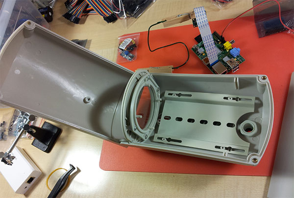
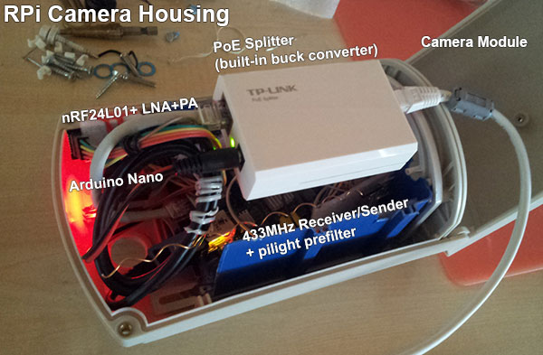
Sending didn't work you mean? Or didn't receiving work either? I've only tested receiving for a few minutes using the debug setting, with the nRF24L01+ LNA+PA and Nano connected to my RPi. Seemed to work ok but it'd be nice to know for sure before investing more time with this particular setup. Also, I don't think I could fit an Uno into my camera housing. I'd have to get a 5V->3.3V converter (one that doesn't ruin radio reception) and take the power directly from the PoE splitter (which currently outputs 5V directly to the RPi TP1/TP2 pins).
Just for fun, here is the setup I have right now, don't laugh ;-)
Anyhow, the Uno allows for 50mA on 3.3V, while the Nano can do 40mA if I'm reading the specs right? Still way off from any 115mA.
-
@jendrush said:
@bjornhallberg At this moment i have gateway on Arduino Uno, and nRF24L01+ LNA+PA is working ok. But when i tried nRF24L01+ LNA+PA with nano it didn't work.
Sending didn't work you mean? Or didn't receiving work either? I've only tested receiving for a few minutes using the debug setting, with the nRF24L01+ LNA+PA and Nano connected to my RPi. Seemed to work ok but it'd be nice to know for sure before investing more time with this particular setup. Also, I don't think I could fit an Uno into my camera housing. I'd have to get a 5V->3.3V converter (one that doesn't ruin radio reception) and take the power directly from the PoE splitter (which currently outputs 5V directly to the RPi TP1/TP2 pins).
Just for fun, here is the setup I have right now, don't laugh ;-)
Anyhow, the Uno allows for 50mA on 3.3V, while the Nano can do 40mA if I'm reading the specs right? Still way off from any 115mA.
@bjornhallberg Why should i laugh?:) Case is a case:) If it's working ok, its ok:)
About Uno and Nano max output - i connected Nano for quick time, and dont know if sending, or receiving work/not work. It just failed as repeater node, and i quickly changed this to standard nRF24L01+. On Uno Gateway nRF24L01+ LNA+PA is working ok all the time. I needed repeater becouse i was trying to receive message from temp+hum outdoor sensor. Now i've received second nRF24L01+ LNA+PA, so i will make PCB for repeater(Arduino Mini Pro, nRF24L01+ LNA+PA, AMS1117 3.3V regulator, and capacitor for radio).
-
(Note this is a resurrected post). I will stick my neck out on this one - hope I have the following correct:
The low noise amp gain is 10dB and the power amplifier is 20 dB. If both ends use the PCB with the LNA & PA, then the link is up 30 dB on the standard radios. With line of sight and that also means the antennas must be high enough to be unaffected by the Fresnel Zone; that being 5.6m high for a distance of one km. Then every 6 dB extra doubles the range. So 30dB/6 = 5 So range is extended by 2^5 = 32 times. It's claimed the powered modules can transmit about 1000m, which implies the standard modules have a line of sight range of about 31m.
However, if you have a standard module at one end and a powered module at the other end, you only increase the link gain by the receiver gain of 10 dB, which just gives 3 times [ = 10^(10dB/20)] the distance of a standard radio, not 32 times [ = 10^(30dB/20)]. So the 31m above get's extended to just about 90m.
It changes for indoors. An approximation is used, whereby 12 dB increase in power is said to be required to double the distance (where only 6dB is required for line of site). So for two high powered radios with 30 dB link gain, this gives a distance increase of 5.6 = 10^(30dB/40) and for one high powered radio and a standard radio where the link gain is improved by only 10 dB, we get a distance improvement of just 1.8 times = 10^(10dB/40)
All the above assumes no electro-magnetic interference from other nearby transmitters, etc.
Outdoors with proper line of site:
32 distance gain 2* high powered radios
3 distance gain high powered radio and a standard radioIndoors approximation:
5.6 distance gain 2* high powered radios
1.8 distance gain high powered radio and a standard radioIf you want distance, you need the high powered modules at both ends.
@a-lurker said:
The low noise amp gain is 10dB and the power amplifier is 20 dB. If both ends use the PCB with the LNA & PA, then the link is up 30 dB on the standard radios.
An low noise amplifier (LNA) with 10 dB gain does not mean the receive sensitivity is 10 dB better, all is dependent on the Noise figure (NF) of the LNA and the nRF24L01+.
I have a nRF24L01+ LNA/PA board and saw it has a RFX2402C on it. The RFX2402C Product Brief tells me that the LNA has 12 dB gain with a NF of 3 dB.
The nRF24L01+ is more difficult, there is no NF nor gain given but what is important is the overall NF, how far is the receive sensitivity above the thermal noise floor?
<background>
*The datasheet says:- Rx sensitivity (0.1% BER) @1Mbps = -85 dBm
- 20 dB Bandwidth for Modulated Carrier (1Mbps) = 900 kHz typ.
To demodulate GFSK with a BER of 10^-3 seems you need about 16..20 dB of SNR, see Fig 3 of this document.
Not sure how much noise bandwidth to take, but let's take 500 kHz. The thermal noise in 500 kHz is -174 + 10 × log(5E5) = -117 dBm.
Combining things: -117 + 16..20 = -101..-97, so the nRF24L01+ has a "NF" of -85 - ( -101..-97) = 12..16 dB.
12..16 dB seems to be a lot for a LNA and if so an external LNA with a NF of 3 dB can really substantially help. But the 12..16 dB is actually the overall receiver performance, so internal LNA, Mixer, Rx Filter and GFSK Demodulator, but only the NF of the LNA is important here*
</background>Try this calculator, the combined NF of the 3 dB NF external LNA combined with the internal LNA is 3..4 dB as long as the internal LNA has a NF < 10 dB.
Based on experience with WiFi chips with an on-chip LNA, such an on-chip LNA can have a NF as low as 4 dB.
Say the nRF24L01+ LNA has a NF of 6 dB then adding the external LNA only buys you 6 - 3.4 = 2.6 dB, not 10 (or 12) dB.
-
Yes the improvement to the noise figure is the prime consideration. A signal buried in the noise, amplified by 10 dB, is still a signal buried in the noise. As you point out the NF is defined primarily by the front end amplifier. As long as the front end has reasonable gain subsequent stages will not contribute substantially to the NF. I've incorrectly used the 10 dB figure as the NF improvement.
So using your figure of 2.6 dB, which looks like an appropriate figure but could be higher; then this suggests, It's really a waste of time using the LNA+PA PCBs unless they are used at both ends. In which case you get the benefit of the power amplifiers and a slight receiver improvement.
Any improvement people may witness with just one end having a LNA+PA PCB is probably just because the LNA+PA PCB uses a far better antenna - the rubber duck versus the PCB antennas. In which case you are probably just as better off using these:
https://www.sparkfun.com/products/705
Noting it has 3V3 regulator built in, that may help with power supply sag, that people are experiencing with the PCB modules - requiring capacitors to be added latter. However they are a bit expensive\e.
@a-lurker said:
So using your figure of 2.6 dB, which looks like an appropriate figure but could be higher; then this suggests, It's really a waste of time using the LNA+PA PCBs unless they are used at both ends.
I largely agree, some refinements:
- If the sensor is mainly sending data and the gateway only acking, it is probably wise to have the PA radio at the sensor as I expect the data messages to be longer than the Acks
- 2.6 dB is not nothing, the range is extended by 34% (new_range = old_range * 1.34) assuming free space
- If the receiving side sees interference (ACI), a 20 dB louder received signal is for sure a better thing
Any improvement people may witness ... is probably just because the LNA+PA PCB uses a far better antenna
Yes, good antenna's can for sure help but be sure you know what you are doing. If you use a dipole antenna and point it to the other node it will not help you and likely even kill your connection.
The antenna efficiency of the on-board antenna's can be pretty good, assuming things are matched correctly. If the external antenna is also matched correctly, it will have about the same efficiency. The same efficiency means that same total power is transmitted.
The remaining difference then is that but the on-board antenna will have less directivity so the energy is spread out more evenly where for instance a dipole will focus most energy perpendicular to the dipole. A pretty good trick, that is how we can still receive signals for the Voyager 1 that is almost out of the solar system using a 20m dish antenna. But ... do point this antenna 1 degree wrong and you will not see the signal.
Hello! It looks like you're interested in this conversation, but you don't have an account yet.
Getting fed up of having to scroll through the same posts each visit? When you register for an account, you'll always come back to exactly where you were before, and choose to be notified of new replies (either via email, or push notification). You'll also be able to save bookmarks and upvote posts to show your appreciation to other community members.
With your input, this post could be even better 💗
Register Login