sensors in boxes


  • I think I must have read almost every page on this site when I discovered it. I really loved this idea. For ages I've wanted to monitor and interact with my surroundings via some home automation solution, but all the commercial solutions are really expensive and limited. MySenors and OpenHAB really give me the customisation I want.

    The only thing missing was putting everything together. I'm working on that. But first I needed to create my sensors, as small/cheap as possible and battery powered.

    Here's my first pass at building the temperature sensor, in a 3D printed box which also houses the battery compartment.

    i2iurp.jpg

    The circuit board (Single Sides Etch) slides in on groves in the walls. I added the battery monitoring to the Arduino as I really need to know if/when the batteries are going flat. That's all pushed back to openHAB which I can then create a rule to watch for battery low, however so far the batteries seem that they will last for ever!

    The contacts on the battery box are small flat metal. Aluminium between the batteries, and Copper for the terminals. I used copper as I could more easily solder to it.

    Making it very easy to assemble.


  • Hi, great project!
    Would you mind sharing a bit more about your circuit? Are you using step-up regulators to power the atmega? Did you etch the PCB yourself or ordered it somewhere?
    I was thinking of a similar project. My idea is to add 3.5mm female jacks to easily add external sensors, e.g external temperature probes, pulse watt counter, etc, and maybe a latching on off switch (but then again, who wants to power off their sensors).


  • I'm running everything at 3 volts from the 2 AAA batteries. The box is 3D printed and integrates the battery box. I'm not using any screws, just slide rails for the PCB , top and back.

    TempSensorBase.stl

    I have two board types now. One with just the single Dallas temp sensor on it, which turns out to be what I need most of.
    tempSensor.png

    I also created another board which has three Connectors, JP1-3, which allows to additional Dallas Temp sensors. I have these in locations where I can run wires more easily, like my loft spaces.

    tempSensor+.png

    I'm etching everything myself. Very simple really. I'm using the print on to glossy paper and transfer onto copper board, using a laminator, method. Works really well. As these boards are small I tend to etch a few at a time onto a single copper board and then cut the board at the end.


  • @GuyP Great looking project! How is your battery level usage so far?


  • Project has now been running for over a month. The study is the Longest running sensor at closer to 2 months.

    As you can see the batteries are still in very good shape... Also I'm still polling every 30seconds for the temp. So if I was worried about the battery I could reduce the poll to say once every 5 minutes and not lose anything in resolution.

    batteryLevels.png


  • @GuyP would you care to share your code for this project?


  • Sure no problem.. It's the stock code for the dallas temperature sensor with the simple addition for the battery monitoring.

    oh and just as an update on that.. still haven't replaced the batteries in the sensors and they are still reporting 82%, which is a run time of over 4 months now.

    BatteryStatus.tiff

    
    // Example sketch showing how to send in OneWire temperature readings
    #include <MySensor.h>  
    #include <SPI.h>
    #include <DallasTemperature.h>
    #include <OneWire.h>
    
    #define ONE_WIRE_BUS 3 // Pin where dallase sensor is connected 
    #define MAX_ATTACHED_DS18B20 16
    unsigned long SLEEP_TIME = 30000; // Sleep time between reads (in milliseconds)
    OneWire oneWire(ONE_WIRE_BUS);
    DallasTemperature sensors(&oneWire);
    MySensor gw;
    float lastTemperature[MAX_ATTACHED_DS18B20];
    int numSensors=0;
    boolean receivedConfig = false;
    boolean metric = true; 
    // Initialize temperature message
    MyMessage msg(0,V_TEMP);
    MyMessage msgvolt(1,V_VOLTAGE);
    int BATTERY_SENSE_PIN = A0;
    int oldBatteryPcnt = 0;
    
    void setup()  
    { 
      analogReference(INTERNAL);
      // Startup OneWire 
      sensors.begin();
    
      // Startup and initialize MySensors library. Set callback for incoming messages. 
      gw.begin(); 
    
      // Send the sketch version information to the gateway and Controller
      gw.sendSketchInfo("Temperature Sensor", "1.0");
    
      // Fetch the number of attached temperature sensors  
      numSensors = sensors.getDeviceCount();
    
      // Present all sensors to controller
      for (int i=0; i<numSensors && i<MAX_ATTACHED_DS18B20; i++) {   
         gw.present(i, S_TEMP);
      }
    }
    
    
    void loop()     
    {     
      // Process incoming messages (like config from server)
      gw.process(); 
    
      // Fetch temperatures from Dallas sensors
      sensors.requestTemperatures(); 
      
      // Battery Monitoring
      int sensorValue = analogRead(BATTERY_SENSE_PIN);
      float batteryV = sensorValue * 0.003363075;
      int batteryPcnt = sensorValue / 10;
      
      Serial.print("Battery Voltage: ");
      Serial.print(batteryV);
      Serial.println(" V");
      
      Serial.print("Battery percent: ");
      Serial.print(batteryPcnt);
      Serial.println(" %");
      
      if (oldBatteryPcnt != batteryPcnt) {
        gw.send(msgvolt.set(batteryPcnt,1));
        oldBatteryPcnt = batteryPcnt;
      }
      // Read temperatures and send them to controller 
      for (int i=0; i<numSensors && i<MAX_ATTACHED_DS18B20; i++) {
     
        // Fetch and round temperature to one decimal
        float temperature = static_cast<float>(static_cast<int>((gw.getConfig().isMetric?sensors.getTempCByIndex(i):sensors.getTempFByIndex(i)) * 10.)) / 10.;
     
        // Only send data if temperature has changed and no error
        if (lastTemperature[i] != temperature && temperature != -127.00) {
     
          // Send in the new temperature
          gw.send(msg.setSensor(i).set(temperature,1));
          lastTemperature[i]=temperature;
        }
      }
      gw.sleep(SLEEP_TIME);
    }


  • Hero Member

    @GuyP what kind of chip is the big one? Does not look like nano or pro mini. Terrific run time so must be efficient.


  • It's an ATMEGA328P, which is the Arduino processor, I buy them in bulk from China, write the boot loader and flash the code onto them using an uno board.


  • Hero Member

    @GuyP Cool! these are really cheap and they save on cutting the LED and voltage regulator.... it looks like they are even more economical in energy then the modified (no LED no voltage reg) pro mini. Can you detail for a complete idiot the bootloader and flash thing?


  • @GuyP Can you post the pdf images of the boards, I want to etch some I like the use of 328P chip, The only problem the png file is scaled wrong too large.


  • @GuyP Do you have a favourite seller for those mega328 DIP parts? Mostly when I've looked on eBay the clone Arduino Mini's come in cheaper than a DIP package mega328 IC. I also would prefer to use a design that utilises the mega328 DIP directly rather than an Arduino Mini if I could. Cost per node is very important to me to enable affordable expansion of my network. Thanks.


  • Hero Member

    @hawk_2050 look here

    That is much cheaper.... 1.4$/node


  • @hawk_2050 I buy them from banggood.com where they discount for quantity so I'm usually paying about £1.66 a chip and free delivery.

    However looking at @Moshe-Livne he's found a cheaper place.. so I think I'll be using them from now on 🙂


  • @Moshe-Livne the boot loader..

    https://www.arduino.cc/en/Hacking/Bootloader?from=Tutorial.Bootloader

    I use this method to write the boot loaders using an uno..

    https://www.arduino.cc/en/Tutorial/ArduinoToBreadboard

    works great. I use a Zero insertion socket for the chip and rattle through the chips in a seconds.


  • @DrJeff Sure no problem..

    TempSensor.pdf

    I've also now built a "Repeater Board", this board can either act as a repeater, and be powered by USB mini, or battery (Best not on battery when in repeater mode). It also has the expansion to add multiple Dallas Temperature sensors. JP1-3 sensors can be daisy chained up to around 16 in total. I have these boards in loft spaces, and garage where I want to watch temperature in lots of locations and I don't mind a few wires.

    RepeaterBoard.png

    TempSensorRepeater.pdf

    Let me know if those work out better...


  • Hero Member

    @GuyP That looks pretty simple... what boot loader do you write? do you really remove the processor from the uno or did you make a dedicated one? do you use the minimal breadboard version? This system also has the upside of not having to deal with the irritating counterfeit or ch340 ftdi chips, so bonus points...


  • @GuyP Cool thanks, Time to etch some boards, have you used this method/setup for other nodes? Just trying to get some ideas 😀


  • @Moshe-Livne When writing the boot loader you need to keep the uno chip in the board.

    Once you've written all the board loaders, then you can pull the chip from uno and replace it with all the new ones to write the temperature sensor codes.


  • @DrJeff At the moment just temperature sensors.. however the plan is to also control my heating system around the house.

    I will put putting controllers on all the radiators around the house, and replacing the controller in the house with simple radio buttons which feed back to openhab for manual over ride.

    Just not had time yet! 😞


  • @GuyP Yes we always got to deal with real life! On the board I assume the red lines are wires due to the single sided board?


  • @DrJeff yes correct.. I'm just etching single sided. I couldn't solve the it completely so four links.


  • @GuyP Are you using the MYS or the Uno bootloader?


  • I'm just flashing with the uno boot loader...

    I have been looking at doing away with the boot loader, but really the advantages such as extra space and boot speed are not important at the moment.


  • Hero Member

    @GuyP can you please export it in brd or dxf?


  • Here's the BRD files..

    TempSensorRepeater.brd

    TempSensor.brd


  • Hero Member

    @GuyP Thanks!!!!


  • Hero Member

    @GuyP Ordered 3 from oshpark... 12$. lets see how quickly they get here. so, other than the sensor and the resistors and oscillator (16mhz?) is there anything else there? I am sorry, I am just hopeless at reading sketchs. Is that a diod on the top left?


  • Sorry my fault... I'm not very good at documentation! 😞

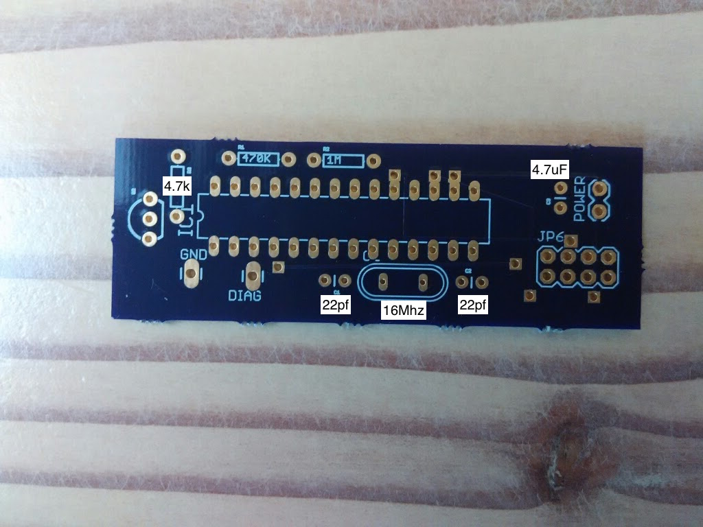
    There are no diodes on the boards... Which board are you referring to.. the TempSensor board just has:

    • 1x dallas Tempensor
    • 2x capacitors for the crystal
    • 1x 16Mhz Crystal
    • 1x 4.7uf Capacitor accros the power lines
    • 1 resistor for the Dallas sensor to provide power
    • 1x 470k resistor and 1x 1m resistor for the battery power level monitoring.

    I don't even have the pins for updating the Arduino, I pull it from the socket and write it in a uno board. I do however have a GND, and serial TX pin so I can see the chip working if necessary.


  • Hero Member

    @GuyP excellent!! That comes out as a really inexpensive and low power board. What sockets do you use? will these work? http://www.aliexpress.com/item/Free-shipping-17PCS-28pin-DIP-IC-sockets-Adaptor-Solder-Type-28-pin-Narrow-body/32313568228.html?spm=2114.32010308.4.2.lkcXJR


  • Yes it's very cheap and simple to build, When I was etching the boards I was etching 12 at a time and cutting them down.

    That 28pin Narrow socket looks to be the right thing (seems to say the right things anyway), the graphic is odd though.

    I also bought all the parts in bulk which made for even more savings, specially for resistors and capacitors where I bought maybe 100 and was paying less than 1p a unit.

    I was also able to buy the Dallas Temp sensors in bulk and saved quite well on those as well


  • Hero Member

    @GuyP Yes, i think that they tried to show what chip fits the socket. They move in mysterious ways... I have all the transistors and capacitors i'll ever need (they are really cheap...) but ordered the oscillators so now I have to wait for a week or two. I am not into etching - seems like something I'll manage to mess up. oshpark will print nice pcbs for you for a really reasonable price. I have ordered only 3 so cost is 4$ each but if you order quantity its much much less (and most of the price is the shipping i think 🙂 ).
    I also have some Dallas so I am all set. As I don't have a 3d printer but really good at woodworking I think i'll build some nice oak boxes for these....


  • Awesome... send photos when you've made them! 🙂


  • Oh a few people have suggested these guys for cheap PCB production..
    http://dirtypcbs.com

    I've not tried them myself yet.


  • Hero Member

    @GuyP They are very cheap per board. Might give them a go if the 3 works fine. early days yet!


  • Hero Member

    @GuyP PCB arrived from oshpark!
    upload_-1 (8).jpg
    What capacitors did you use for the crystal? and what resistor for the dallas?


  • Ok now I'm jealous.. that looks fantastic.

    1437172414002-upload_-1-8.jpg


  • Hero Member

    @GuyP It does... Now I realize that if I knew what I was doing (and I don't) it could probably be made smaller and no need for soldering at all.

    Thanks! will let you know how it worked out. Might take a bit of time as I am now finishing my AirCon remote sensor.


  • @GuyP Can you post the 3d files for the box in original post if possible?


  • @Moshe-Livne Any progress?
    can you please explain how this pcb be smaller with no need for soldering
    Where are you from?


  • Hero Member

    @oded00 Still waiting for the 22pf capacitors...
    It was made in resolution for home made PCBs and single layer. oshpark can make the lines much smaller and make more layers so there is no need for soldering the "red" lines. you still need to solder the components (nrf, capacitors etc)
    I live in NZ


  • @GuyP If I order this brd files online, I assume that I need to remove the red lines from the top layer? Or maybe reroute them if possible? Looks like some short circuit connections.


  • Hero Member

    @pjeterinfo Oh I didn't notice them. Darn, and I soldered the wires...


  • Yes You'll want to remove or reroute them. I was only think of a single layer board so those are link wires. Sorry I should have talked about those.


  • I order a few with modified toplayer to fit all the "red" wires and removed 2mm of the board width.
    tempsensor.brd


  • Excellent...be careful, not to remove too much from the right side, as the radio transmitter will over hang which makes it harder to fit in a box.


  • @Moshe-Livne said:

    @GuyP PCB arrived from oshpark!
    upload_-1 (8).jpg
    What capacitors did you use for the crystal? and what resistor for the dallas?

    What is the name for this board on OSHpark? I would like to order 3 of these boards myself


  • Hero Member

    @mntlvr don't use this as it has shorts. Use the corrected one someone posted a few comments back


  • @Moshe-Livne said:

    @mntlvr don't use this as it has shorts. Use the corrected one someone posted a few comments back

    Thanks Moshe-Livne but I can't find any comments on this posting about anyone buying boards that work can you help with this or is it best just to make your own?


  • Hero Member

    @mntlvr said:

    @Moshe-Livne said:

    @mntlvr don't use this as it has shorts. Use the corrected one someone posted a few comments back

    Thanks Moshe-Livne but I can't find any comments on this posting about anyone buying boards that work can you help with this or is it best just to make your own?

    Just upload the brd file pjeterinfo posted


  • Use it on your own risk, it's nog yet arrived and thus not tested 😉


  • Hero Member

    @pjeterinfo I still need to cut the traces on mine....


  • IMG_20150812_203817.jpg

    All parts received and programmed using a pro mini, man that's frustrating 😉 . But works great..


  • Hi,
    Nice little board.

    Do you know how long does the dallas temp sensor keeps working on?
    I ask this because its minumun supply voltage is 3.0V and you are feeding the board exactly with that.
    So, what happens when the battery voltage get a bit below 3.0V?

    Thanks, regards.


  • @gonzalonal We'll see, I have setup datamine for this sensor in Vera.


  • @GuyP many posts ago you guided @Moshe-Livne to arduino cc/ file for downloading the bootloader files but I see only the files for 168 DIP and not 328P
    Do I use the 168p file?


Log in to reply
 

Suggested Topics

  • 8
  • 1
  • 3
  • 2
  • 2
  • 1

18
Online

11.2k
Users

11.1k
Topics

112.5k
Posts