Controlling Relay Actuator
-
Looking for some help with relay actuator and serial gateway.
Having setup multiple arduino's with NRF's all working well when sending data to the gateway.
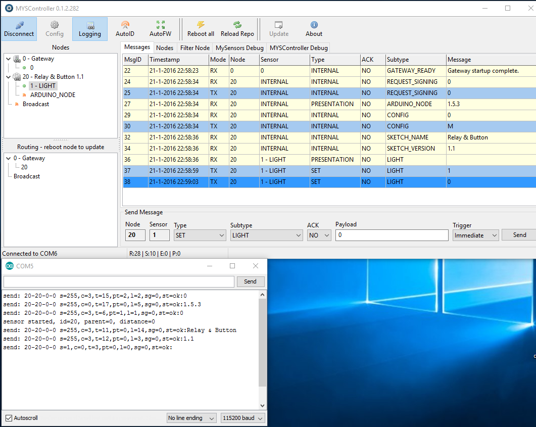
For some reason no way to send anything to a sensor from the gateway with Domoticz or MYSControllerDoes anyone recognize an issue in the screenshot?
Using different Arduino's with different NRF's + Caps, 3.3v measured ( but according to serial log there is communication )Thanks for the support!
-
Sorry..the last 2 blue lines in the picture are send via MYSController, but no result in serial output of the sensor or a relay ticking....( relay is working when pressing physical button )
-
Im using the default example sketch 1.5.3:
/** * The MySensors Arduino library handles the wireless radio link and protocol * between your home built sensors/actuators and HA controller of choice. * The sensors forms a self healing radio network with optional repeaters. Each * repeater and gateway builds a routing tables in EEPROM which keeps track of the * network topology allowing messages to be routed to nodes. * * Created by Henrik Ekblad <henrik.ekblad@mysensors.org> * Copyright (C) 2013-2015 Sensnology AB * Full contributor list: https://github.com/mysensors/Arduino/graphs/contributors * * Documentation: http://www.mysensors.org * Support Forum: http://forum.mysensors.org * * This program is free software; you can redistribute it and/or * modify it under the terms of the GNU General Public License * version 2 as published by the Free Software Foundation. * ******************************* * * DESCRIPTION * The ArduinoGateway prints data received from sensors on the serial link. * The gateway accepts input on seral which will be sent out on radio network. * * The GW code is designed for Arduino Nano 328p / 16MHz * * Wire connections (OPTIONAL): * - Inclusion button should be connected between digital pin 3 and GND * - RX/TX/ERR leds need to be connected between +5V (anode) and digital pin 6/5/4 with resistor 270-330R in a series * * LEDs (OPTIONAL): * - To use the feature, uncomment WITH_LEDS_BLINKING in MyConfig.h * - RX (green) - blink fast on radio message recieved. In inclusion mode will blink fast only on presentation recieved * - TX (yellow) - blink fast on radio message transmitted. In inclusion mode will blink slowly * - ERR (red) - fast blink on error during transmission error or recieve crc error * */ #define NO_PORTB_PINCHANGES #include <MySigningNone.h> #include <MyTransportRFM69.h> #include <MyTransportNRF24.h> #include <MyHwATMega328.h> #include <MySigningAtsha204Soft.h> #include <MySigningAtsha204.h> #include <SPI.h> #include <MyParserSerial.h> #include <MySensor.h> #include <stdarg.h> #include <PinChangeInt.h> #include "GatewayUtil.h" #define INCLUSION_MODE_TIME 1 // Number of minutes inclusion mode is enabled #define INCLUSION_MODE_PIN 3 // Digital pin used for inclusion mode button #define RADIO_ERROR_LED_PIN 4 // Error led pin #define RADIO_RX_LED_PIN 6 // Receive led pin #define RADIO_TX_LED_PIN 5 // the PCB, on board LED // NRFRF24L01 radio driver (set low transmit power by default) MyTransportNRF24 transport(RF24_CE_PIN, RF24_CS_PIN, RF24_PA_LEVEL_GW); //MyTransportRFM69 transport; // Message signing driver (signer needed if MY_SIGNING_FEATURE is turned on in MyConfig.h) //MySigningNone signer; //MySigningAtsha204Soft signer; //MySigningAtsha204 signer; // Hardware profile MyHwATMega328 hw; // Construct MySensors library (signer needed if MY_SIGNING_FEATURE is turned on in MyConfig.h) // To use LEDs blinking, uncomment WITH_LEDS_BLINKING in MyConfig.h #ifdef WITH_LEDS_BLINKING MySensor gw(transport, hw /*, signer*/, RADIO_RX_LED_PIN, RADIO_TX_LED_PIN, RADIO_ERROR_LED_PIN); #else MySensor gw(transport, hw /*, signer*/); #endif char inputString[MAX_RECEIVE_LENGTH] = ""; // A string to hold incoming commands from serial/ethernet interface int inputPos = 0; boolean commandComplete = false; // whether the string is complete void parseAndSend(char *commandBuffer); void output(const char *fmt, ... ) { va_list args; va_start (args, fmt ); vsnprintf_P(serialBuffer, MAX_SEND_LENGTH, fmt, args); va_end (args); Serial.print(serialBuffer); } void setup() { gw.begin(incomingMessage, 0, true, 0); setupGateway(INCLUSION_MODE_PIN, INCLUSION_MODE_TIME, output); // Add interrupt for inclusion button to pin PCintPort::attachInterrupt(pinInclusion, startInclusionInterrupt, RISING); // Send startup log message on serial serial(PSTR("0;0;%d;0;%d;Gateway startup complete.\n"), C_INTERNAL, I_GATEWAY_READY); } void loop() { gw.process(); checkButtonTriggeredInclusion(); checkInclusionFinished(); if (commandComplete) { // A command wass issued from serial interface // We will now try to send it to the actuator parseAndSend(gw, inputString); commandComplete = false; inputPos = 0; } } /* SerialEvent occurs whenever a new data comes in the hardware serial RX. This routine is run between each time loop() runs, so using delay inside loop can delay response. Multiple bytes of data may be available. */ void serialEvent() { while (Serial.available()) { // get the new byte: char inChar = (char)Serial.read(); // if the incoming character is a newline, set a flag // so the main loop can do something about it: if (inputPos<MAX_RECEIVE_LENGTH-1 && !commandComplete) { if (inChar == '\n') { inputString[inputPos] = 0; commandComplete = true; } else { // add it to the inputString: inputString[inputPos] = inChar; inputPos++; } } else { // Incoming message too long. Throw away inputPos = 0; } } } -
just enabled led blinking for the gateway. When pressing relay sensor button: RX and TX blink on serial gateway + serial out:
send: 0-0-0-0 s=1,c=1,t=2,pt=2,l=2,sg=0,st=ok:0
read: 0-0-0 s=1,c=1,t=2,pt=2,l=2,sg=0:0
This is an ack from gateway
Incoming change for sensor:1, New status: 0italicised textWhen controlling with Domoticz or MYSController....nothing send to the serial gateway, no TX, RX
:( Spending hours without any progress
Is there something i did not configure? Just using the example sketch for the serial gateway and enabled Led's in myconfig
-
Please post your actuator sketch not the GW. As said above, maybe you are not handling the incoming data to the actuator correctly.
-
Im using the example RelayWithButtonActuator:
/** * The MySensors Arduino library handles the wireless radio link and protocol * between your home built sensors/actuators and HA controller of choice. * The sensors forms a self healing radio network with optional repeaters. Each * repeater and gateway builds a routing tables in EEPROM which keeps track of the * network topology allowing messages to be routed to nodes. * * Created by Henrik Ekblad <henrik.ekblad@mysensors.org> * Copyright (C) 2013-2015 Sensnology AB * Full contributor list: https://github.com/mysensors/Arduino/graphs/contributors * * Documentation: http://www.mysensors.org * Support Forum: http://forum.mysensors.org * * This program is free software; you can redistribute it and/or * modify it under the terms of the GNU General Public License * version 2 as published by the Free Software Foundation. * ******************************* * * REVISION HISTORY * Version 1.0 - Henrik Ekblad * * DESCRIPTION * Example sketch for a "light switch" where you can control light or something * else from both HA controller and a local physical button * (connected between digital pin 3 and GND). * This node also works as a repeader for other nodes * http://www.mysensors.org/build/relay */ #include <MySensor.h> #include <SPI.h> #include <Bounce2.h> #define RELAY_PIN 4 // Arduino Digital I/O pin number for relay #define BUTTON_PIN 3 // Arduino Digital I/O pin number for button #define CHILD_ID 1 // Id of the sensor child #define RELAY_ON 1 #define RELAY_OFF 0 Bounce debouncer = Bounce(); int oldValue=0; bool state; MySensor gw; MyMessage msg(CHILD_ID,V_LIGHT); void setup() { gw.begin(incomingMessage, AUTO, true); // Send the sketch version information to the gateway and Controller gw.sendSketchInfo("Relay & Button", "1.0"); // Setup the button pinMode(BUTTON_PIN,INPUT); // Activate internal pull-up digitalWrite(BUTTON_PIN,HIGH); // After setting up the button, setup debouncer debouncer.attach(BUTTON_PIN); debouncer.interval(5); // Register all sensors to gw (they will be created as child devices) gw.present(CHILD_ID, S_LIGHT); // Make sure relays are off when starting up digitalWrite(RELAY_PIN, RELAY_OFF); // Then set relay pins in output mode pinMode(RELAY_PIN, OUTPUT); // Set relay to last known state (using eeprom storage) state = gw.loadState(CHILD_ID); digitalWrite(RELAY_PIN, state?RELAY_ON:RELAY_OFF); } /* * Example on how to asynchronously check for new messages from gw */ void loop() { gw.process(); debouncer.update(); // Get the update value int value = debouncer.read(); if (value != oldValue && value==0) { gw.send(msg.set(state?false:true), true); // Send new state and request ack back } oldValue = value; } void incomingMessage(const MyMessage &message) { // We only expect one type of message from controller. But we better check anyway. if (message.isAck()) { Serial.println("This is an ack from gateway"); } if (message.type == V_LIGHT) { // Change relay state state = message.getBool(); digitalWrite(RELAY_PIN, state?RELAY_ON:RELAY_OFF); // Store state in eeprom gw.saveState(CHILD_ID, state); // Write some debug info Serial.print("Incoming change for sensor:"); Serial.print(message.sensor); Serial.print(", New status: "); Serial.println(message.getBool()); } } -
I have read alot of reports here lately with this issue in both Domoticz and Vera (pushing button works, but not sending from controller to relay). I dont know why but i tried it myself with 2.0b and exact the same behaivour. It works with my 1.4 relays but not 2.0...
I have no more info at this time but will try to figure something out when i have the time...
-
Have not been able to test this (@ work), but according to Domoticz github it looks like Domoticz sends V_STATUS to update a Lightning2.
In the sketch we have message.type == V_LIGHTS_LIGHT, // Binary light or relay, V_STATUS (or V_LIGHT), V_WATTSendNodeSetCommand(node_id, child_sensor_id, MT_Set, V_STATUS, lState, pChild->useAck);MySensors Github RelayWityButtonAcc
if (message.type == V_LIGHT) {Im not that good in understanding coding, but this would be the first im going to experiment with tonight.
-
V_LIGHT and V_STATUS are complementary to each other they are both are defined as 2.
There are however a couple of remarks regarding your code.
- when the button is pressed only a message is sent to the GW the relay is not toggled
- when a state change request is received there is no status update sent to the gatewat
- a minor issue debouncer.update() return true when a change change was detected so you do not have to remember the old state.
All three comments I've processed in the sketch below you might want to try this
/** * The MySensors Arduino library handles the wireless radio link and protocol * between your home built sensors/actuators and HA controller of choice. * The sensors forms a self healing radio network with optional repeaters. Each * repeater and gateway builds a routing tables in EEPROM which keeps track of the * network topology allowing messages to be routed to nodes. * * Created by Henrik Ekblad <henrik.ekblad@mysensors.org> * Copyright (C) 2013-2015 Sensnology AB * Full contributor list: https://github.com/mysensors/Arduino/graphs/contributors * * Documentation: http://www.mysensors.org * Support Forum: http://forum.mysensors.org * * This program is free software; you can redistribute it and/or * modify it under the terms of the GNU General Public License * version 2 as published by the Free Software Foundation. * ******************************* * * REVISION HISTORY * Version 1.0 - Henrik Ekblad * * DESCRIPTION * Example sketch for a "light switch" where you can control light or something * else from both HA controller and a local physical button * (connected between digital pin 3 and GND). * This node also works as a repeader for other nodes * http://www.mysensors.org/build/relay */ #include <MySensor.h> #include <SPI.h> #include <Bounce2.h> #define RELAY_PIN 4 // Arduino Digital I/O pin number for relay #define BUTTON_PIN 3 // Arduino Digital I/O pin number for button #define CHILD_ID 1 // Id of the sensor child #define RELAY_ON 1 #define RELAY_OFF 0 Bounce debouncer = Bounce(); bool state; MySensor gw; MyMessage msg(CHILD_ID,V_LIGHT); void setup() { gw.begin(incomingMessage, AUTO, true); // Send the sketch version information to the gateway and Controller gw.sendSketchInfo("Relay & Button", "1.0"); // Setup the button pinMode(BUTTON_PIN,INPUT); // Activate internal pull-up digitalWrite(BUTTON_PIN,HIGH); // After setting up the button, setup debouncer debouncer.attach(BUTTON_PIN); debouncer.interval(5); // Register all sensors to gw (they will be created as child devices) gw.present(CHILD_ID, S_LIGHT); // Make sure relays are off when starting up digitalWrite(RELAY_PIN, RELAY_OFF); // Then set relay pins in output mode pinMode(RELAY_PIN, OUTPUT); // Set relay to last known state (using eeprom storage) state = gw.loadState(CHILD_ID); digitalWrite(RELAY_PIN, state?RELAY_ON:RELAY_OFF); } /* * Example on how to asynchronously check for new messages from gw */ void loop() { gw.process(); // Get the update value and if push button was release toggle the relay and send an update to the gw if (debouncer.update() && debouncer.read() != 0) { state = state ? true : false; gw.send(msg.set(state?false:true), true); // Send new state and request ack back digitalWrite(RELAY_PIN, state?RELAY_ON:RELAY_OFF); } } void incomingMessage(const MyMessage &message) { // We only expect one type of message from controller. But we better check anyway. if (message.isAck()) { Serial.println("This is an ack from gateway"); } if (message.type == V_LIGHT) { // Change relay state state = message.getBool(); digitalWrite(RELAY_PIN, state?RELAY_ON:RELAY_OFF); // Store state in eeprom gw.saveState(CHILD_ID, state); // Send new state to the GW gw.send(msg.set(state?false:true)); // Write some debug info Serial.print("Incoming change for sensor:"); Serial.print(message.sensor); Serial.print(", New status: "); Serial.println(message.getBool()); } } -
Sorry about that... yea see that they are the same now. Spared me some time there BartE - tnx. He is using the standard sketch and this has been working great ever since... strange.
-
V_LIGHT and V_STATUS are complementary to each other they are both are defined as 2.
There are however a couple of remarks regarding your code.
- when the button is pressed only a message is sent to the GW the relay is not toggled
- when a state change request is received there is no status update sent to the gatewat
- a minor issue debouncer.update() return true when a change change was detected so you do not have to remember the old state.
All three comments I've processed in the sketch below you might want to try this
/** * The MySensors Arduino library handles the wireless radio link and protocol * between your home built sensors/actuators and HA controller of choice. * The sensors forms a self healing radio network with optional repeaters. Each * repeater and gateway builds a routing tables in EEPROM which keeps track of the * network topology allowing messages to be routed to nodes. * * Created by Henrik Ekblad <henrik.ekblad@mysensors.org> * Copyright (C) 2013-2015 Sensnology AB * Full contributor list: https://github.com/mysensors/Arduino/graphs/contributors * * Documentation: http://www.mysensors.org * Support Forum: http://forum.mysensors.org * * This program is free software; you can redistribute it and/or * modify it under the terms of the GNU General Public License * version 2 as published by the Free Software Foundation. * ******************************* * * REVISION HISTORY * Version 1.0 - Henrik Ekblad * * DESCRIPTION * Example sketch for a "light switch" where you can control light or something * else from both HA controller and a local physical button * (connected between digital pin 3 and GND). * This node also works as a repeader for other nodes * http://www.mysensors.org/build/relay */ #include <MySensor.h> #include <SPI.h> #include <Bounce2.h> #define RELAY_PIN 4 // Arduino Digital I/O pin number for relay #define BUTTON_PIN 3 // Arduino Digital I/O pin number for button #define CHILD_ID 1 // Id of the sensor child #define RELAY_ON 1 #define RELAY_OFF 0 Bounce debouncer = Bounce(); bool state; MySensor gw; MyMessage msg(CHILD_ID,V_LIGHT); void setup() { gw.begin(incomingMessage, AUTO, true); // Send the sketch version information to the gateway and Controller gw.sendSketchInfo("Relay & Button", "1.0"); // Setup the button pinMode(BUTTON_PIN,INPUT); // Activate internal pull-up digitalWrite(BUTTON_PIN,HIGH); // After setting up the button, setup debouncer debouncer.attach(BUTTON_PIN); debouncer.interval(5); // Register all sensors to gw (they will be created as child devices) gw.present(CHILD_ID, S_LIGHT); // Make sure relays are off when starting up digitalWrite(RELAY_PIN, RELAY_OFF); // Then set relay pins in output mode pinMode(RELAY_PIN, OUTPUT); // Set relay to last known state (using eeprom storage) state = gw.loadState(CHILD_ID); digitalWrite(RELAY_PIN, state?RELAY_ON:RELAY_OFF); } /* * Example on how to asynchronously check for new messages from gw */ void loop() { gw.process(); // Get the update value and if push button was release toggle the relay and send an update to the gw if (debouncer.update() && debouncer.read() != 0) { state = state ? true : false; gw.send(msg.set(state?false:true), true); // Send new state and request ack back digitalWrite(RELAY_PIN, state?RELAY_ON:RELAY_OFF); } } void incomingMessage(const MyMessage &message) { // We only expect one type of message from controller. But we better check anyway. if (message.isAck()) { Serial.println("This is an ack from gateway"); } if (message.type == V_LIGHT) { // Change relay state state = message.getBool(); digitalWrite(RELAY_PIN, state?RELAY_ON:RELAY_OFF); // Store state in eeprom gw.saveState(CHILD_ID, state); // Send new state to the GW gw.send(msg.set(state?false:true)); // Write some debug info Serial.print("Incoming change for sensor:"); Serial.print(message.sensor); Serial.print(", New status: "); Serial.println(message.getBool()); } }Regarding 1.
I think the point is to wait for the acknowledge from the controller before changing relay state, after the press of the button. -
and regarding 2 - why send a statusupdate to controller when the status comes from the controller? The ack should be enough?
-
So, recreated this now - all standard sketch (2.0b) except I used pin 5 instead of pin4 for relay (due to PCB pinout layout, should not matter).
Everything works great both from Domoticz and Myscontroller but there was some small issues...
-
Power - my pro mini was just a little to weak to trigger the relay... :( It needs 5v but my pin 5 was only giving 4.7V and some tries resulted in a unsuccessful relay switch even if the logs told me so.
-
Radio - at some points i had the radio to close to the gw, so it didnt get the ACK and therefore i got the error "Error sending command, check device/hardware" message in Domoticz .
This is from Myscontroller, sending a on command with ack:
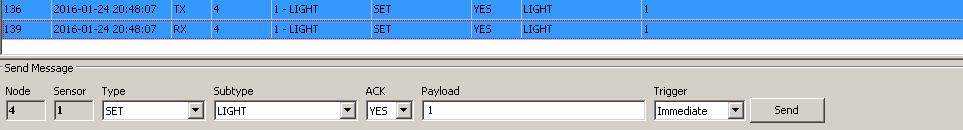
Correct seriallog node when incoming command from controller
read: 0-0-4 s=1,c=1,t=2,pt=0,l=1,sg=0:1
send: 4-4-0-0 s=1,c=1,t=2,pt=0,l=1,sg=0,st=ok:1
Incoming change for sensor:1, New status: 1What i dont know if why it works one way (command) but not the other (ack). I guess my GW radio is stronger, bigger or better powered.
-
-
@sundberg84 your right the ack should be enough
@martinhjelmare this should be enough, but when for some reason your network is down you'r not able to control the devices locally
-
Yes, good point.
Maybe one could have a timeout event that compares button state with relay state, and after three failed comparisons, turns off the waiting for the acknowledge, as a sign of network failure.
-
@BartE, @martinhjelmare - this is sometime we should work with in the standard sketch.
I have one relay on the edge and sometimes its having really hard to get that ack back from the controller and it never changes. It would be good if the relay made the switch, send the on/off to controller and waited for the ack. If you dont recieve it you send again and tries for some times.
Hello! It looks like you're interested in this conversation, but you don't have an account yet.
Getting fed up of having to scroll through the same posts each visit? When you register for an account, you'll always come back to exactly where you were before, and choose to be notified of new replies (either via email, or push notification). You'll also be able to save bookmarks and upvote posts to show your appreciation to other community members.
With your input, this post could be even better 💗
Register Login