Help Me!!! Hardware problem arduino uno gateway
-
Have you tried to power from the DC-in socket instead of the usb. I think I've read that just the usb isn't enough for the ethernet shield. And avoid use both at the same time unless you're really sure about that it wont destroy anything.
Edit: You should be safe with keeping the usb connected and using a good quality supply. And of course you'll need the usb to debug. -
server.write(writeBuffer); in EthernetGateway.ino stops arduino!!!
If I comment server.write(writeBuffer); in function writeEthernet(char *writeBuffer) arduino uno receive and transmit data via radio.
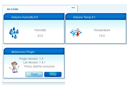
Node Humidity
req node id
send: 255-255-0-0 s=255,c=3,t=3,pt=0,l=0,st=ok:
sensor started, id 255
req node id
send: 255-255-0-0 s=255,c=3,t=3,pt=0,l=0,st=ok:
req node id
send: 255-255-0-0 s=255,c=3,t=3,pt=0,l=0,st=ok:
req node id
send: 255-255-0-0 s=255,c=3,t=3,pt=0,l=0,st=ok:
req node id
send: 255-255-0-0 s=255,c=3,t=3,pt=0,l=0,st=fail:
req node id
send: 255-255-0-0 s=255,c=3,t=3,pt=0,l=0,st=ok:
req node id
send: 255-255-0-0 s=255,c=3,t=3,pt=0,l=0,st=ok:
req node id
send: 255-255-0-0 s=255,c=3,t=3,pt=0,l=0,st=fail:
T: 22.00
req node id
send: 255-255-0-0 s=255,c=3,t=3,pt=0,l=0,st=fail:
H: 39.00Gateway without server.write(writeBuffer);
0;0;3;0;14;Gateway startup complete.
gateway is at 192.168.0.166
0;0;3;0;9;read: 255-255-0 s=255,c=3,t=3,pt=0,l=0:
255;255;3;0;3;
0;0;3;0;9;read: 255-255-0 s=255,c=3,t=3,pt=0,l=0:
255;255;3;0;3;
0;0;3;0;9;read: 255-255-0 s=255,c=3,t=3,pt=0,l=0:
255;255;3;0;3;
0;0;3;0;9;read: 255-255-0 s=255,c=3,t=3,pt=0,l=0:
255;255;3;0;3;
0;0;3;0;9;read: 255-255-0 s=255,c=3,t=3,pt=0,l=0:
255;255;3;0;3;Thank
Gigi -
My configuration!!!!
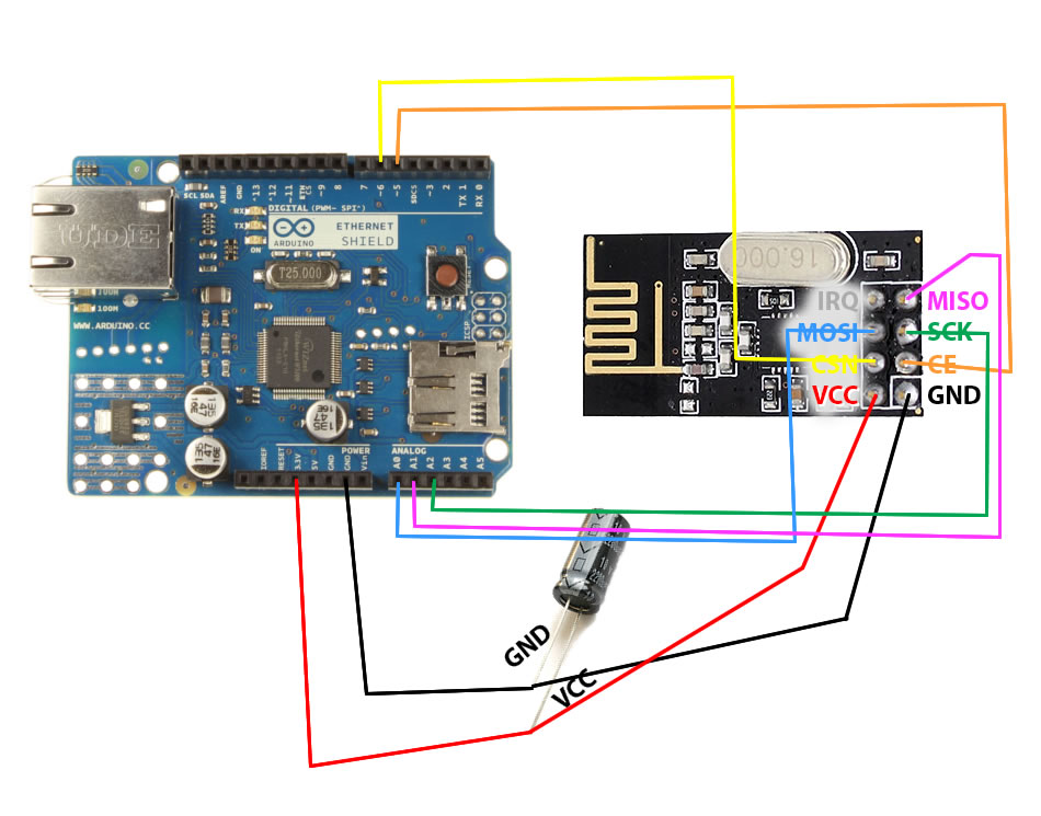
circuit diagram
in RF24_config.h
enable softspi (remove // before "#define SOFTSPI").change
const uint8_t SOFT_SPI_MISO_PIN = 15;
const uint8_t SOFT_SPI_MOSI_PIN = 14;
const uint8_t SOFT_SPI_SCK_PIN = 16;arduino sketch
/*- Copyright (C) 2013 Henrik Ekblad henrik.ekblad@gmail.com
- Contribution by a-lurker
- Contribution by Norbert Truchsess norbert.truchsess@t-online.de
- This program is free software; you can redistribute it and/or
- modify it under the terms of the GNU General Public License
- version 2 as published by the Free Software Foundation.
- DESCRIPTION
- The EthernetGateway sends data received from sensors to the ethernet link.
- The gateway also accepts input on ethernet interface, which is then sent out to the radio network.
- The GW code is designed for Arduino 328p / 16MHz. ATmega168 does not have enough memory to run this program.
- COMPILING WIZNET (W5100) ETHERNET MODULE
-
Edit RF24_config.h in (libraries\MySensors\utility) to enable softspi (remove // before "#define SOFTSPI").
- COMPILING ENC28J60 ETHERNET MODULE
-
Use Arduino IDE 1.0.6 or 1.5.7 (or later)
-
Not compatible with Arduino IDE < 1.0.6 / 1.5.7 ! (use of EthernetClient operator ==)
-
Disable DEBUG in Sensor.h before compiling this sketch. Othervise the sketch will probably not fit in program space when downloading.
-
Remove Ethernet.h include below and include UIPEthernet.h
-
Remove DigitalIO include
- Note that I had to disable UDP and DHCP support in uipethernet-conf.h to reduce space. (which means you have to choose a static IP for that module)
- VERA CONFIGURATION:
- Enter "ip-number:port" in the ip-field of the Arduino GW device. This will temporarily override any serial configuration for the Vera plugin.
- E.g. If you want to use the defualt values in this sketch enter: 192.168.178.66:5003
- LED purposes:
-
- RX (green) - blink fast on radio message recieved. In inclusion mode will blink fast only on presentation recieved
-
- TX (yellow) - blink fast on radio message transmitted. In inclusion mode will blink slowly
-
- ERR (red) - fast blink on error during transmission error or recieve crc error
- See http://www.mysensors.org/build/ethernet_gateway for wiring instructions.
- in RF24_config.h
- decommentare #define SOFTSPI riga 28 enable softspi (remove // before "#define SOFTSPI").
- const uint8_t SOFT_SPI_MISO_PIN = 15;
- const uint8_t SOFT_SPI_MOSI_PIN = 14;
- const uint8_t SOFT_SPI_SCK_PIN = 16;
- radio Pin
- ARDUINO RADIO
- pin 5 --> CE
- pin 6 --> CSN
- pin A0 --> MOSI
- pin A1 --> MISO
- pin A2 --> SCK
*/
#include <DigitalIO.h> // This include can be removed when using UIPEthernet module
#include <SPI.h>
#include <MySensor.h>
#include <MyGateway.h>
#include <stdarg.h>
// Use this if you have attached a Ethernet ENC28J60 shields
//#include <UIPEthernet.h>
// Use this fo WizNET W5100 module and Arduino Ethernet Shield
#include <Ethernet.h>
#define INCLUSION_MODE_TIME 1 // Number of minutes inclusion mode is enabled
#define INCLUSION_MODE_PIN 3 // Digital pin used for inclusion mode button
#define RADIO_CE_PIN 5 // radio chip enable
#define RADIO_SPI_SS_PIN 6 // radio SPI serial select
#define RADIO_ERROR_LED_PIN 7 // Error led pin
#define RADIO_RX_LED_PIN 8 // Receive led pin
#define RADIO_TX_LED_PIN 9 // the PCB, on board LED
#define IP_PORT 5003 // The port you want to open
IPAddress myIp (192, 168, 0, 166); // Configure your static ip-address here COMPILE ERROR HERE? Use Arduino IDE 1.5.7 or later!
// The MAC address can be anything you want but should be unique on your network.
// Newer boards have a MAC address printed on the underside of the PCB, which you can (optionally) use.
// Note that most of the Ardunio examples use "DEAD BEEF FEED" for the MAC address.
byte mac[] = { 0xDE, 0xAD, 0xBE, 0xEF, 0xFE, 0xED }; // DEAD BEEF FEED
// a R/W server on the port
EthernetServer server = EthernetServer(IP_PORT);
// handle to open connection
EthernetClient client = EthernetClient();
// No blink or button functionality. Use the vanilla constructor.
MyGateway gw(RADIO_CE_PIN, RADIO_SPI_SS_PIN, INCLUSION_MODE_TIME);
// Uncomment this constructor if you have leds and include button attached to your gateway
//MyGateway gw(RADIO_CE_PIN, RADIO_SPI_SS_PIN, INCLUSION_MODE_TIME, INCLUSION_MODE_PIN, RADIO_RX_LED_PIN, RADIO_TX_LED_PIN, RADIO_ERROR_LED_PIN);
char inputString[MAX_RECEIVE_LENGTH] = ""; // A string to hold incoming commands from serial/ethernet interface
int inputPos = 0;
void setup()
{
// Initialize gateway at maximum PA level, channel 70 and callback for write operations
gw.begin(RF24_PA_LEVEL_GW, RF24_CHANNEL, RF24_DATARATE, writeEthernet);
Ethernet.begin(mac, myIp);
// give the Ethernet interface a second to initialize
delay(1000);
// start listening for clients
server.begin();
}
// This will be called when data should be written to ethernet
void writeEthernet(char *writeBuffer) {
client.write(writeBuffer);
}
void loop()
{
// if an incoming client connects, there will be
// bytes available to read via the client object
EthernetClient newclient = server.available();
// if a new client connects make sure to dispose any previous existing sockets
if (newclient) {
if (client != newclient) {
client.stop();
client = newclient;
client.print(F("0;0;3;0;14;Gateway startup complete.\n"));
}
}
if (client) {
if (!client.connected()) {
client.stop();
// if got 1 or more bytes
} else if (client.available()) {
// read the bytes incoming from the client
char inChar = client.read();
if (inputPos<MAX_RECEIVE_LENGTH-1) {
// if newline then command is complete
if (inChar == '\n') {
// a command was issued by the client
// we will now try to send it to the actuator
inputString[inputPos] = 0;
// echo the string to the serial port
Serial.print(inputString);
gw.parseAndSend(inputString);
// clear the string:
inputPos = 0;
} else {
// add it to the inputString:
inputString[inputPos] = inChar;
inputPos++;
}
} else {
// Incoming message too long. Throw away
inputPos = 0;
}
}
}
gw.processRadioMessage();
}here is the result
thank to Norbert Truchsess for skecth
-
Please indent any code 4 spaces before pasting to make it easier to read.
Did you try an external power source? -
@m26872 said:
Did you try an external power source?
I don't try external power source. In this moment is connect to usb cable from pc!!@kalle said:
Im not sure it is a typo or you tried to ping different IP's
In the third post you write "but no ping to 192.168.0.66" instead of 192.168.0.166 which is written in the sketch, maybe this is the problem.
Ip is 192.168.0.166
Thank
-
What is your progress? Now it works?
It is better to use a power supply instead of USB power with the Ethernetshield.@kalle said:
What is your progress? Now it works?
It is better to use a power supply instead of USB power with the Ethernetshield.I put arduino and ethernet and shield directly connected with PC USB.
Are two weeks and works without problems.even if the PC is powered off the USB supply current!!!!
Merry Christmas and Happy Holidays!!!!
-
@kalle said:
What is your progress? Now it works?
It is better to use a power supply instead of USB power with the Ethernetshield.I put arduino and ethernet and shield directly connected with PC USB.
Are two weeks and works without problems.even if the PC is powered off the USB supply current!!!!
Merry Christmas and Happy Holidays!!!!
Hello, I only managed to make it work ties in:
#define SOFTSPI
#ifdef SOFTSPI
const uint8_t SOFT_SPI_MISO_PIN = 12; //A0
const uint8_t SOFT_SPI_MOSI_PIN = 11; // A1
const uint8_t SOFT_SPI_SCK_PIN = 13; // A0
#endifI do not know how to explain.
Hello! It looks like you're interested in this conversation, but you don't have an account yet.
Getting fed up of having to scroll through the same posts each visit? When you register for an account, you'll always come back to exactly where you were before, and choose to be notified of new replies (either via email, or push notification). You'll also be able to save bookmarks and upvote posts to show your appreciation to other community members.
With your input, this post could be even better 💗
Register Login