Yet another PCB to address (nearly) all Arduino pins
-
Hi TD,
many thanks for the library, I incorporated the drill holes and it looks much better now!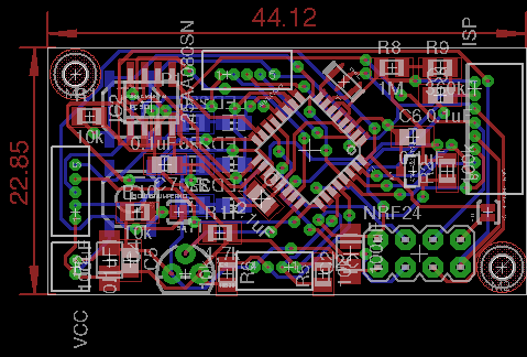
Best regards,
Philipp@phil83 said:
Hi TD,
many thanks for the library, I incorporated the drill holes and it looks much better now!
Best regards,
PhilippHI Philipp,
Will you like to share your files with this final version of your PCB? This is an excellent stuff. Appreciate your design skills...
-
Hi TD,
many thanks for the library, I incorporated the drill holes and it looks much better now!
Best regards,
Philipp@phil83 If small is the target, use the SMD version of the NRF24L01+. Here is a small NRF24 library.
-
Nice board, but still would suggest MYSX.. It's got different variants, with more / less pins available..
I'm playing around with a boardlayout that's 18x30mm, with MYSX connector, and nrf24 (SMD) the NRF will protrude over one end of the board with ~5-7mm (Antenna area). so total length will be 18x37mm (or something in that area).
-
One more tip: If you want to order a full 10x10 cm board, you can panelize them yourself and use https://github.com/p12tic/eagle-brd-merge to get around the 10x8 limit in the free version of Eagle. Worked great for my mother/daughter board order.
-
Hi all,
many thanks for all the valuable input!
I will share my files after having tested the board by myself for the first time!@GertSanders: I've never thought about using the SMD version of NRF24L01, it really looks interesting!
@tbowmo: Your board size is really impressive, are you also using the EEPROM and ATSHA on that small size board?
The smallest and still (hopefully) manufacturable for me seems to be around 44x21mm...
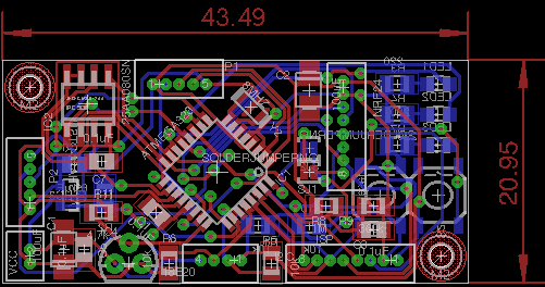
Right now I'm waiting for all of the parts of my reflow oven, I have some boards for testing here and in case I'm successful with reflowing, I will order new boards in China.Best regards,
Philipp -
-
@tbowmo I have been working on a similar board. The matter of external connections for switches and external sensors keeps me busy. The 1,27 mm spaced headers seem like a possible solution. But I have not found any female headers with wires (Dupont style) to go with the male versions. How do you solve the connection problem ?
-
@GertSanders: On aliexpress you can find sets of male and female 1.25mm connectors, do you think about something like that:
http://de.aliexpress.com/item/20sets-Micro-1-25mm-5pin-Cable-JST-1-25-5-Pin-Male-Female-Connector-plug-with/32464250609.html?spm=2114.010208.3.2.BMcTZF&ws_ab_test=searchweb201556_9,searchweb201644_5_505_506_503_504_301_10020_502_10001_10002_10017_10010_10005_10006_10011_10003_10021_10004_10022_10009_10008_10018_10019,searchweb201560_2,searchweb1451318400_-1,searchweb1451318411_6448&btsid=8ded8c25-db33-49ed-835b-307cb83c0f47 -
As I read your post again, you mean something like this:
http://de.aliexpress.com/item/5-sets-Double-Row-Female-Socket-SMD-2-10-20pin-1-27mm-Pin-Header-connector/32542921161.html?isOrigTitle=true -
@GertSanders: On aliexpress you can find sets of male and female 1.25mm connectors, do you think about something like that:
http://de.aliexpress.com/item/20sets-Micro-1-25mm-5pin-Cable-JST-1-25-5-Pin-Male-Female-Connector-plug-with/32464250609.html?spm=2114.010208.3.2.BMcTZF&ws_ab_test=searchweb201556_9,searchweb201644_5_505_506_503_504_301_10020_502_10001_10002_10017_10010_10005_10006_10011_10003_10021_10004_10022_10009_10008_10018_10019,searchweb201560_2,searchweb1451318400_-1,searchweb1451318411_6448&btsid=8ded8c25-db33-49ed-835b-307cb83c0f47@phil83 the micro connector set with the wires is a very good suggestion. I will look around some more.
-
I finally went on with the project and received the pcbs last week... my soldering oven is running and I could finish the first board (still some parts are missing :-( ) If only I had more time to work on that...
Here are some impressions: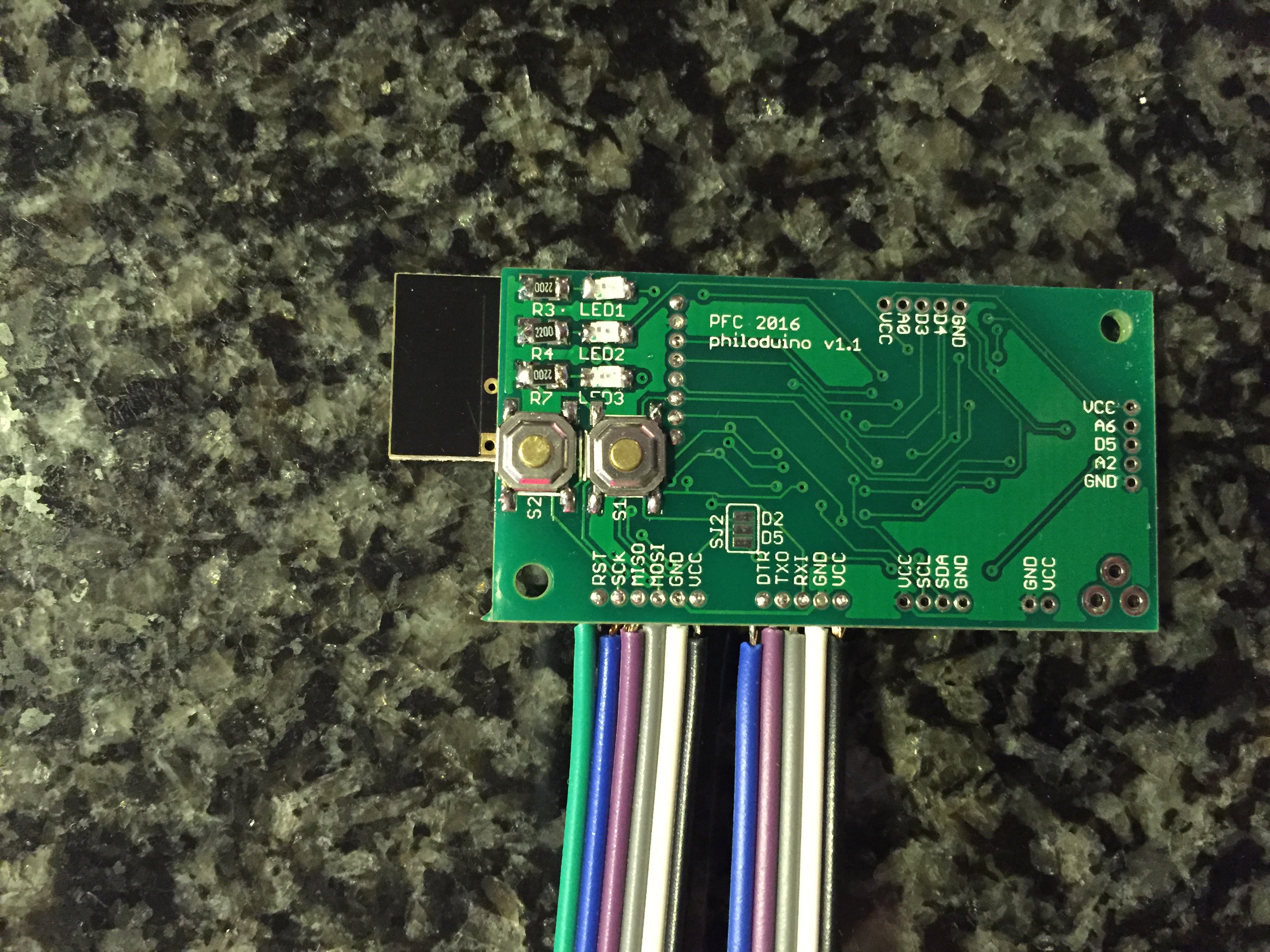
I soldered some cables so that I can program it and check via ftdi...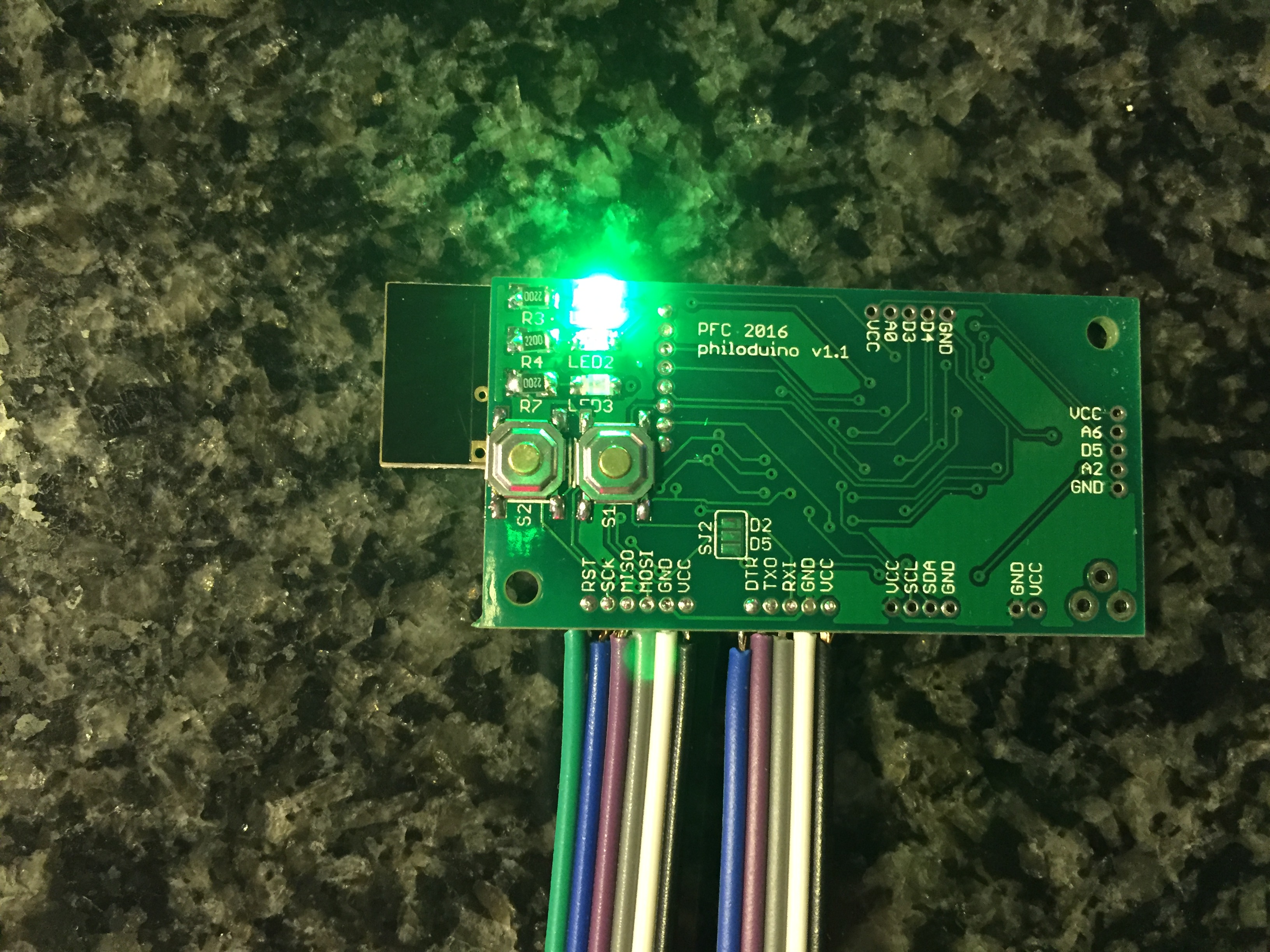
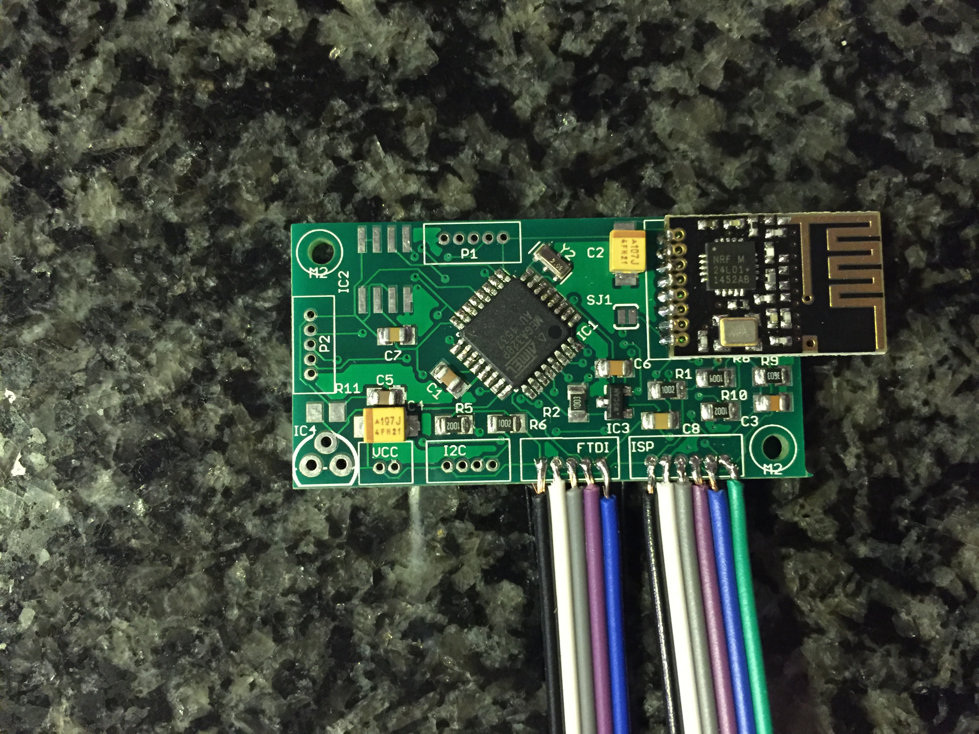
More to come soon...
-
I finally went on with the project and received the pcbs last week... my soldering oven is running and I could finish the first board (still some parts are missing :-( ) If only I had more time to work on that...
Here are some impressions:
I soldered some cables so that I can program it and check via ftdi...

More to come soon...
@phil83
Share this on OpenHardware.io !
