Water meter: Itron Aquadis+ with pulse sensor


  • Hi all,

    I started using the TCRT5000 module on my Aquadis+ water meter (see photo). The TCRT is connected to an Arduino Uno currently. After fiddling around with it for a while I found that the configuration actually counts two pulses for each litre of water. The TCRT is aligned on the metal disc, but I suspect it to also trigger on the red needle. Does anyone has the same experience with this water meter in this configuration?
    Thanks in advance,

    Ralph
    Aquadis+.jpeg


  • @bisschopsr I have the same water meter. I found out that placing the TCRT5000 sensor near the edge gives one pulse for each litre (the needle is not seen). When the sensor closer to the center two pulse per litre are seen.
    I prefer the second position (better resolution).


  • @meijeren Thanks! That helps and confirms my suspicion. I will keep it positioned this way. Did you change anything to the script fi. PULSE_FACTOR to 2000?


  • @bisschopsr Yes. You need to change the pulse factor 2000.


  • Thats what I thought. The only thing I need to figure out is how to do this with Domoticz, my controller software. That however should not be to hard to do.


  • Hero Member

    this works well within domoticz, only the initial value is not managed...


  • @epierre the initial value can be managed by changing the value in MySensors through MYSController by adding it as a command. Domoticz requires some database changes unfortunately.


  • @meijeren It seems like I get occasional massive miscounts. During the last four days I had a night with +87 litre and a night with +595 litre. I think this happens random although we did run the dishwasher during this nights. During all other times the count was in line with the actual meter readings. Did you change anything on the values for MAX_FLOW, attachInterrupt (currently on falling flank) or the 0.5sek debounce setting? I found some people do change this.


  • Hero Member

    on a residia, I found a way that makes no error:
    http://forum.mysensors.org/topic/1647/water-meter-grey-scale-sensor/1


  • @epierre Did not know this sensor. However for the Aquadis+ meter this does not look like a good solution. It should reflect the metal piece compared to the white background. Also the led might spread the light too much for the sensor.


  • Hero Member

    @bisschopsr hopefully not for the tone was quite small on the other and it worked perfectly well ! I think on the x0.0001 you could do that to detect the red cursor moving around.


  • Today I had another massive miscount. As expected this is happening random. I realigned the sensor 4 days ago. Until now the mismatch was 0. Today I had a +975 litre count in one hour. This is getting a little frustrating now. Any suggestions anyone?


  • @bisschopsr said:

    TCRT5000 module...
    What happens if the mirror is barely in position to reflect and the counter stay at rest or is moving very slowly?
    I'm afraid that it will trigger many false events instead of just one (maybe depending on the ambient light).
    Probably using a couple of detectors and trigger only when both see the reflection can help.


  • @salvato said:

    @bisschopsr said:

    TCRT5000 module...
    What happens if the mirror is barely in position to reflect and the counter stay at rest or is moving very slowly?
    I'm afraid that it will trigger many false events instead of just one (maybe depending on the ambient light).
    Probably using a couple of detectors and trigger only when both see the reflection can help.

    That is what I was thinking also. It must happen when the dish is stopped with the edge close to the detector or really moving slow. I was also thinking about using a second detector and only trigger when both see the dish. This might however mean modding a TCRT5000 sensor. Ambient light will not be the problem. The sensor and the dish are shielded from external light sources.


  • Mod

    @bisschopsr probably the number of miscounted can be reduced in software, by measuring the time between two successive pulses.
    Measure the maximum number of counts per time unit you will ever need to count (e.g open all valves completely and see how fast it runs). Any pulses coming in faster can be ignored as they are fakes.
    This will probably not eliminate all miscounts, but I suspect it will reduce it a lot.


  • @Yveaux Hi, Thx for the feedback however IMHO I believe this won't solve it. At some point I had a miscount of 47 litre's. This is something that can actually happen in normal life. I do agree with you for the big deviations where 950 litre is counted in a span of 15 minutes.


  • Mod

    @bisschopsr I suspect your issue is a combination of 'bouncing' sensor levels when switching and possibly flaky readouts when the wheel just happens to stop right below the sensor.
    Bouncing sensor levels can be fixed by monitoring the rate of change in a certain interval. E.g. when at maximum water usage you get one count every second, then any pulses coming in at a higher rate then once a second can be regarded fakes.
    You currently don't know if these 950 litres are counted in one second, or one hour, correct?

    Anyway, if you have access to an oscilloscope you could connect it to the water meter sensor and see what signal actually comes out of it.
    Then you'll know what's causing the problem and you can start thinking of a solution.


  • @Yveaux said:

    @bisschopsr I suspect your issue is a combination of 'bouncing' sensor levels when switching and possibly flaky readouts when the wheel just happens to stop right below the sensor.
    Bouncing sensor levels can be fixed by monitoring the rate of change in a certain interval. E.g. when at maximum water usage you get one count every second, then any pulses coming in at a higher rate then once a second can be regarded fakes.
    You currently don't know if these 950 litres are counted in one second, or one hour, correct?

    Anyway, if you have access to an oscilloscope you could connect it to the water meter sensor and see what signal actually comes out of it.
    Then you'll know what's causing the problem and you can start thinking of a solution.

    Hi @Yveaux , I fully agree with your conclusion however this occurs only once every few days (I wish it was more often to enable analytics). I can do some analytics as the result is sent to my controller (Domoticz) every 5 minutes. That how I know it’s happening in a short timespan within the hour (in five minute frames). I believe it to happen when the silver dish or the red needle stops with the edge near the sensor. The sensor then starts floating slightly around the Schmitt triggers (LM 393) switch point. As the Schmitt trigger circuit has no hysteresis, this results inevitably in pulses to the Arduino. I’m considering two solutions. 1) built a hardware hysteresis around the LM393. 2) built in software hysteresis by using one of the analog pins of the Arduino. I prefer to do the latter since its more tuneable.


  • Hi, I don't know if this is easy to do but if if the red needle and the mirror are in different positions you could use a sort of flip-flop having two sensors one that set the FF and the other that reset it.


  • @salvato said:

    Hi, I don't know if this is easy to do but if if the red needle and the mirror are in different positions you could use a sort of flip-flop having two sensors one that set the FF and the other that reset it.

    I was looking into this. However I figured this might require another interupt capable pin which is not available anymore (if you want to do it from software). On the other hand a hardware solution might be feasable. The LM393 for one has two comperators.


  • I just follow for now, because I have the same water meter.


  • Hello,
    I was reading this forum and this can be also a solution.I have the same problems with reading the water meter.
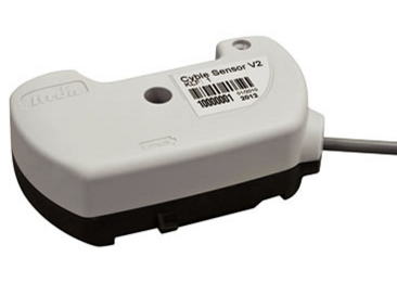
    Use a special sensor for the Aquadis+, it costs about 70 Euro. (search for Cyble sensor)
    upload-975ca954-5946-4e84-828e-aae28489d8cd
    Datasheet sensor: https://www.itron.com/PublishedContent/Cyble_Sensor_pb_EN_12-11.pdf
    I have not tried this sensor yet.
    Rob


  • @rob.21 Thanks for the addition. This is indeed the original Itron device for enabling pulse counting on the standard Aquadis+. Although probably the best solution (no hassle, just fits, avoids miscounting) it's rather expensive. Also it's a hard to buy one and even more important, it runs on a non-replaceable battery. The ones I found on the market have a battery of 5 years old (I believe the battery should last for 10). And don't forget about the fun of building it yourself!


  • Hi All,
    Herewith an update of my effort to get this working correctly. I decided to try and work with the analogue value coming from the TCRT5000. I adapted the original MySensors watermeter sketch to enable the use of the analogue input. I put in a software hysteresis mechanism and β€˜tools’ to check the values coming from the TCRT. This appeared to be very successful the setup has been running now 24/7 since January 1st. The result so fa is zero miscounts! The counter value is the same as the reading on the meter itself. I will post more details later and I will upload everything to Github, so the code, the pictures of the setup and the PCB I’m developing for this.


  • Hi all,

    The design and the sketch are on github. Link
    https://github.com/rbisschops/mySensors/tree/master/Watermeter

    This is an early stage design. Any feedback is welcome!

    Ralph


  • Hi All,

    The water meter sensor has been running as of Jan 1st without a litre deviation compared to the actual water meter reading. That is 2 month! This week I received the most of the parts for the board. Made some final changed to the layout (see Github and Openhardware.io for the files). This week I will do a final quality check on the board. After that the order for the board goes out.


  • Just the let you know, the board is submitted for production (V0.10). Now I have to wait patiently. Meanwhile I probably will work on the sketch, get the parts not used anymore out. Also I need to further write the manual.


  • Thanks for developing this. It works excellent with my water meter flawlessly, but does not appear to me the "water flow". No device in the domoticz.


  • @Klon This might be a Domoticz problem. DO you see water flow when you for instance connect with a tool like MYSController? My interest is about counting water consumption, so I did not pay attention to flow (yet). I dismantled the test setup a week ago, so can't test.


  • I just received the PCB's, so I will start to build the first proto somewhere this week. I will update the progress to the forum as soon as I have results.


  • Unfortunately in MYSControler also does not have information about the flow of water.


  • @Klon: Hi Klon, I chacked the code. It might be that the flow is not sent becaus I disabled the interupt of D3. I will have to make some changes to the code to get it working again. I will look into it.


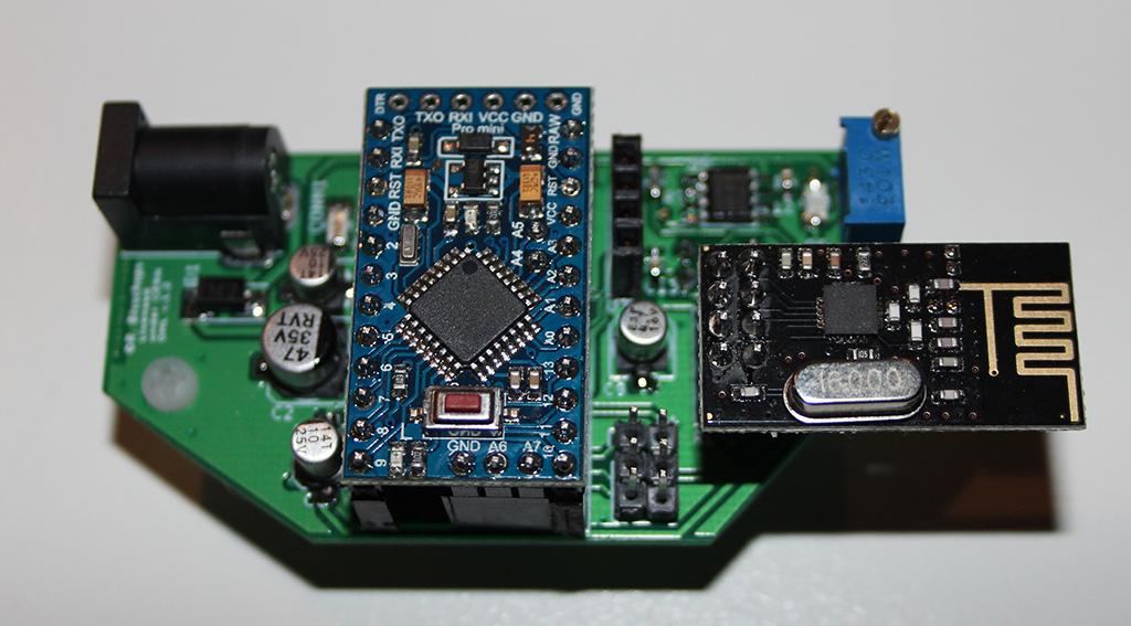
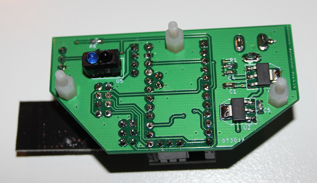
  • Hi all I soldered the PCB's this week. There is one little error in the boards, so not to bad. Today I tested the board for the first time. It is working perfectly. I must however say that the board does not yet contain the EEPROM and the ATSHA, so that part is not tested (yet). I also have to adapt the sketch for the Temperature sensor (SI7021), so that parts also remains to be tested.
    Herewith some pictures of the PCB.
    0_1459009138784_IMG_2977.JPG 0_1459009144654_IMG_2979.JPG


  • Hi All,
    Just to add a picture of the assembled sensor with its housing. The housing was a little strugle to get it to fit the meter. The top of the meter is not flat. Eventually I found the best fitting solution. The "housing" was laser cut and consists of three parts, a base plate, a plate to fit the PCB and a protective top plate with some text. The base plate has a screw to fixate the sensor to the meter.
    0_1462518954749_IMG_2987_small.jpg

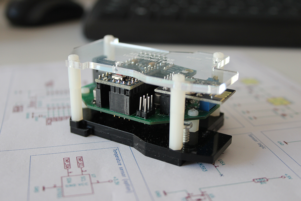
    I will post a picture of the sensor on the meter later.


  • Hi All,

    The sensor is finally in production on my home water meter. I just uploaded the latest version of the pcb documents to OpenHardware.io. Not bad only one small error in the PCB design. Easily fixed so no need for ordering new boards.


  • Mod

    @bisschopsr Thanks for sharing! πŸ‘
    Will you be able to make it to the MySensors meetup at July 30th in Breda?
    Would be very nice if you can show it there!


  • Hi @Yveaux thanks for bringing the meetup to my attention. I will look at it (found the thread). As this is very close to my summer holiday I will have to see if I can be there. I will keep you posted.

    Thanks

    Ralph


  • @hek : I'm in the process of converting my sketch to the 2.0.0 release of mySensors. As I work in Visual Studio (instead of the standard IDE) I noticed that there is an error generated for the following line:

    send(lastCounterMsg.set(pulseCount));
    

    This line is also in the original (converted) sketch at line 140. If I change the line in line with the other send commands so something like this:

    send(lastCounterMsg.set(pulseCount,3));
    

    the error is gone.

    So my questions are:
    What is the correct way to write the code line?
    Is the 2.0.0 release more critical to this?

    Note: The standard IDE compiles the code without an error.
    Thx in advance,

    Ralph


  • Admin

    Using the following feels wrong. It isn't a float value you're transmitting.

    send(lastCounterMsg.set(pulseCount,3));


  • Mod

    @bisschopsr can you post the error message? Maybe that will help in fixing the error...


  • @hek: I agree with you, its not a float. I tried it to see how the interperter of VS responds. I did not mention this eralier, but I use the Visual Micro plugin in VS.
    @Yveaux: I took a quick screenshot of the error message:
    0_1471890856999_upload-7568068c-c9b2-4431-b3a9-e3706238d4ba

    As I see it the interperter expects the function as it is, somehow it does report an error though.

    Regards,
    Ralph


  • Mod

    @bisschopsr thanks for posting the actual error message; that helps a lot πŸ˜„
    Apparently the type of pulseCount is volatile unsigned long.
    The MyMessage class has no set() - method directly taking this type as input, so the compiler starts looking for the next closest match. It finds 3: bool, uint8_t and int32_t and can't make a choice. That's why you get the error.
    To fix it, either change the type of pulseCount to one of the supported types, or cast it to one of these types just before calling the set() - method on the message.


  • @Yveaux As you might have understood, I'm not that experienced in the language. But I think I get the explanation you gave. Indeed pulseCount is of type volatile unsigned long. So if I change it to for example int32_t, will the Arduino compiler still understand and use a similar type as unsigned long? On the other hand, I guess this is related to the libraries of mySensors, isn’t it? So should the library not support unsigned long as well?

    Thanks again,

    Ralph


  • Mod

    @bisschopsr depends... Currently the library understands a lot of c++ types, but not all as you have seen.
    Choosing a comparable type will simply fix your issues. The int32_t is identical to unsigned long on Arduino, except for the sign. If your values do not exceed 2^31 you can just as well store it in an int32_t, but keep the volatile: volatile uint32_t pulseCount
    Maybe we can add some template trickery to the library to support all c++ types.


  • Hi

    @bisschopsr : I try to put my TCRT5000 sensor on the Aquadis but I am not satisfied of the position/orientation. Would you send me a draw with the position of the two LEDS over the aquadis itron ?

    thanks


  • @samuel-wieczorek Hi Samuel. I positioned the sensor over the 1 liter wheel. I did not used the TCRT5000 module, but made a custom built PCB. Howver the principle is the same (in fact the schematics is 100% the same as the TCRT module.
    If you go to https://www.openhardware.io/view/15/Itron-Aquadis-watermeter-sensor-V10 you can see pictures of the module. Some tips I can share with you:
    Shield the sensor and the rotating disk area from incoming light. This influences the sensor. Use a piece of plastic tube for example. In NL we have electrical wire tubes that can be used (the grey ones)
    Bring the sensor close to the disk. The reflection should do the rest. Setting up the TCRT is tricky as you have little room to manouver (considering reflection and the point where the schmit trigger swaps state)
    Be aware that when the disk stops with the edge near the sensor you get false readings. That is why I swapped to a software driven solution using SW hysteresis on the arduino.
    Hope this helps. If you can open it, I can share a DXF file with the sizes of the bottom plate I use. Let me know!

    Ralph


Log in to reply
 

Suggested Topics

  • 87
  • 3
  • 2
  • 1
  • 10
  • 8

0
Online

11.2k
Users

11.1k
Topics

112.5k
Posts