Fuses to protect attached relays on board?
-
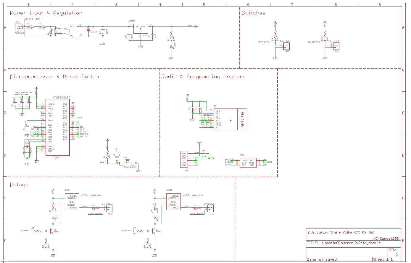
I'm mid process of making a double relay board to automate some lighting around the house and in the garden. The issues that i'm facing here is the use of fuses. Because i'm supplying the AC power from the AC INPUT on the board itself the only fuse protection that the attached device will have is back at the ring main fuse board in the house. The schematic is below (In image and .sch file in case you can't see the image clearly enough), just in case I'm not completely explaining properly. There will not be any motors or pumps attached to this and therefor i'm thinking that there will never be a current overload on this module, the only thing that i'm worried about it issues with the circuits attached, such as shorting out for some reason or even if its a garden module, the lighting casing could fail and cause a short circuit via rain or something maybe.
As you can see in the schematic shown below, the relay power is coming from the input AC power (top left).
The module isn't finished yet, i'm still to put on security and then maybe a current sensor along with a temperature sensor for inside of the enclosure maybe, however if it gets too hot the thermal fuse will do its job anyway, so not seeing much need for the temp sensor. The current sensor would be installed on the input terminal before the AC power gets used for anything so it can monitor the overall current used on the module itself including the relays attached.
-
I'm mid process of making a double relay board to automate some lighting around the house and in the garden. The issues that i'm facing here is the use of fuses. Because i'm supplying the AC power from the AC INPUT on the board itself the only fuse protection that the attached device will have is back at the ring main fuse board in the house. The schematic is below (In image and .sch file in case you can't see the image clearly enough), just in case I'm not completely explaining properly. There will not be any motors or pumps attached to this and therefor i'm thinking that there will never be a current overload on this module, the only thing that i'm worried about it issues with the circuits attached, such as shorting out for some reason or even if its a garden module, the lighting casing could fail and cause a short circuit via rain or something maybe.
As you can see in the schematic shown below, the relay power is coming from the input AC power (top left).
The module isn't finished yet, i'm still to put on security and then maybe a current sensor along with a temperature sensor for inside of the enclosure maybe, however if it gets too hot the thermal fuse will do its job anyway, so not seeing much need for the temp sensor. The current sensor would be installed on the input terminal before the AC power gets used for anything so it can monitor the overall current used on the module itself including the relays attached.
@Samuel235
Instead of transistors you can use cheap FETs: 2N7000 with a 150Ohm resistor between mcu pin and gate. The FET would be in the same position as the transistor, and you save a resistor
As for fuses, I depend on the normal glass fuses (10A in my case for my 10A relay). Mounting them vertical allows a minimal PCB space, depends on the room you have above the PCB. -
@Samuel235
Instead of transistors you can use cheap FETs: 2N7000 with a 150Ohm resistor between mcu pin and gate. The FET would be in the same position as the transistor, and you save a resistor
As for fuses, I depend on the normal glass fuses (10A in my case for my 10A relay). Mounting them vertical allows a minimal PCB space, depends on the room you have above the PCB.@GertSanders, of course FETs would be a better solution for the switching. However, how does this remove a resistor, because from what i'm aware of, if you want the MOSFET to be open (off) while the MCU is powering up or turned off then its still best practice to have a pulldown resistor from gate to gnd. I'm trying to use parts that i can source in decent quantities for this module, do you think the below N-Channel Enhancement Mode MOSFET would work fine, it states its a 2.5v switching MOSFET so i'd like to think this is classed as a logic-level device?
Device: http://www.aliexpress.com/item/FREE-SHIPPING-Free-Shipping-200pcs-lot-N-Channel-MOSFET-2SK3018-100MA-30V-KN-SOT23-SMD-Triode/1996891927.html?spm=2114.30010308.3.30.RYjbCG&ws_ab_test=searchweb201556_10,searchweb201602_2_10037_10033_507_10032_10020_10017_10021_10022_10009_10008_10018_101_10019,searchweb201603_2&btsid=0c50ce82-e4b2-47ba-946b-79d737a60762
Datasheet: http://www.gmesemi.com/userfiles/product/1321344998959.pdfMy thoughts on the fuse situation is that IF a device blows the fuse protecting the relay i would want to either replace the relay and the fuse too or replace the whole module. I wouldn't like to risk it not have already damaged the relay. So, whats your thoughts of putting in a SMT/SMD fuse soldered to the board as any fuse that i solder to the board (lead or SMT) need to be de-soldered to replace, and i have no issue de-soldering SMT devices. So, i have proposed to use this fuse.
Hello! It looks like you're interested in this conversation, but you don't have an account yet.
Getting fed up of having to scroll through the same posts each visit? When you register for an account, you'll always come back to exactly where you were before, and choose to be notified of new replies (either via email, or push notification). You'll also be able to save bookmarks and upvote posts to show your appreciation to other community members.
With your input, this post could be even better 💗
Register Login