Custom node for USA wall switch module
-
Love the project. Can't wait to see more. Please share your designs, would love to do this for my North American home as well.
Oh, and is it possible to get some high-resolution pictures of your project?
Thanks,
My Projects
2 Door Chime Sensor
Washing Machine Monitor -
Love the project. Can't wait to see more. Please share your designs, would love to do this for my North American home as well.
Oh, and is it possible to get some high-resolution pictures of your project?
Thanks,
-
Updated first post.
Better pictures and the newly create sensor plate which contains DHT22 and Motion and attaches to the node.
More to come.
-
Thanks @enterprised
Are you using any fuses in line with your power supply?
-
I have two designs of my node.
First generation, as in the pictures, where I use an fuse in the hot wire.
Second generation where thermal fuse and varistor are on the pcb. -
My latest project.
After years using X10 and ZWave I hit the limit with these devices where they simply do not conform to my evolving home control requirements.
Having played with Arduino's and MySensors quite a bit I decided to create my own devices based on MySensors and MQTT.
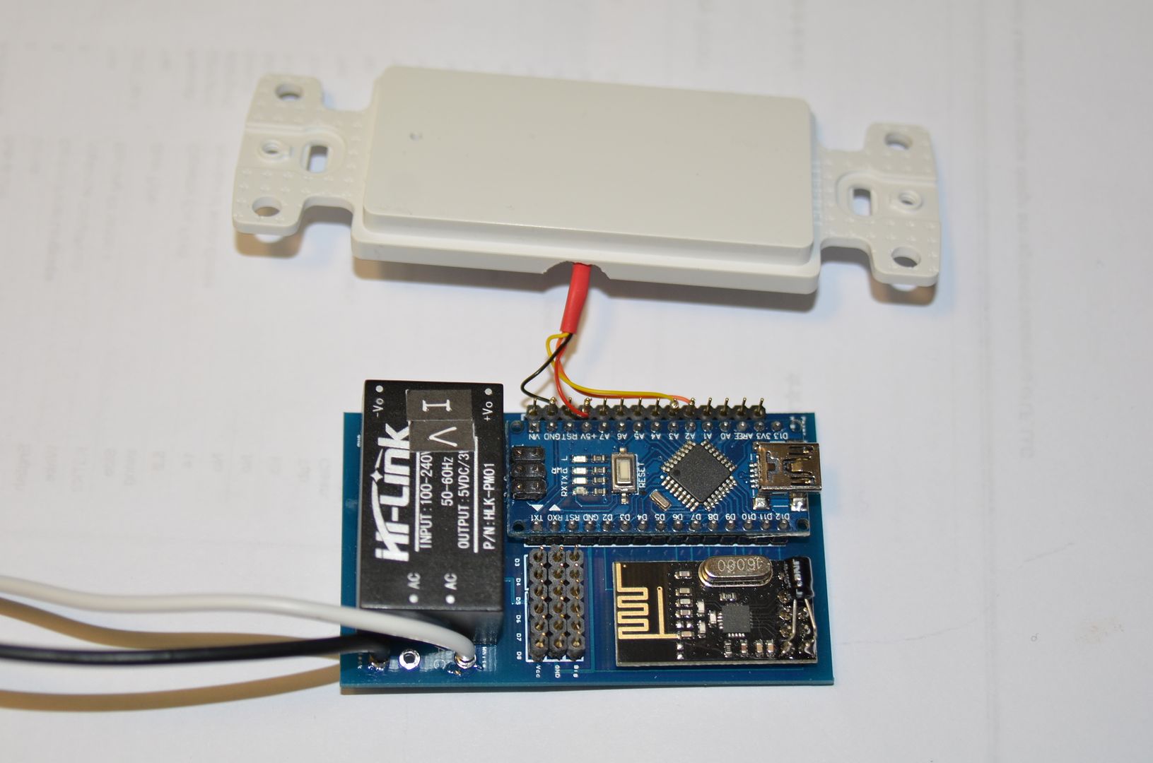
I designed a custom PCB for a custom node holding a Arduino Nano, the 2.4Hz RF module, a universal PSU and all required connections for up to 6 switches, 4 relays, DHT and Motion sensor.
I had the PCB printed by PCBWay (www.pcbway.com) in China. Their price for small batch prototype boards was great. Their service and speed of delivery was excellent. The quality of the PCB's I received is very high.
After cutting the PCB's in two, as I had two designs on each board, I ended with a PCB perfectly sized for a standard USA wall switch.
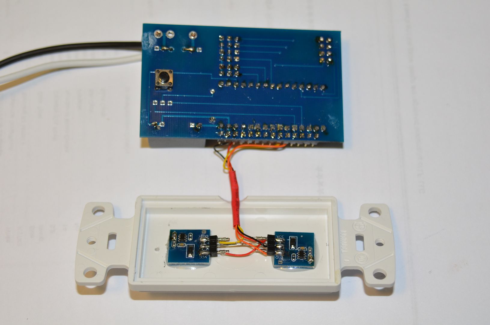
I'm using wall switch blank plates, with two captive touch sensors installed and a small hole drilled for the reset switch. The populated and completed PCB is than glued on the the back side of the blank plate. I used some good old fashioned wire wrapping technique to connect the touch switch wires to the PCB.
The now ready switch unit fits perfectly, with one relay module, in a single wall switch box, pr with up to 4 relay modules in a dual wall switch box.
I have 3 of these modules installed now, and in progress of completing another 5.
The touch switches work really well. They will activate if you come within 5mm from the wall switch unit. The two switches in each unit do not interfere with each other, so no accidental switch activation.
Read my post at HomeGenie for additional detail homegenie.it
Update - 10 July 2016
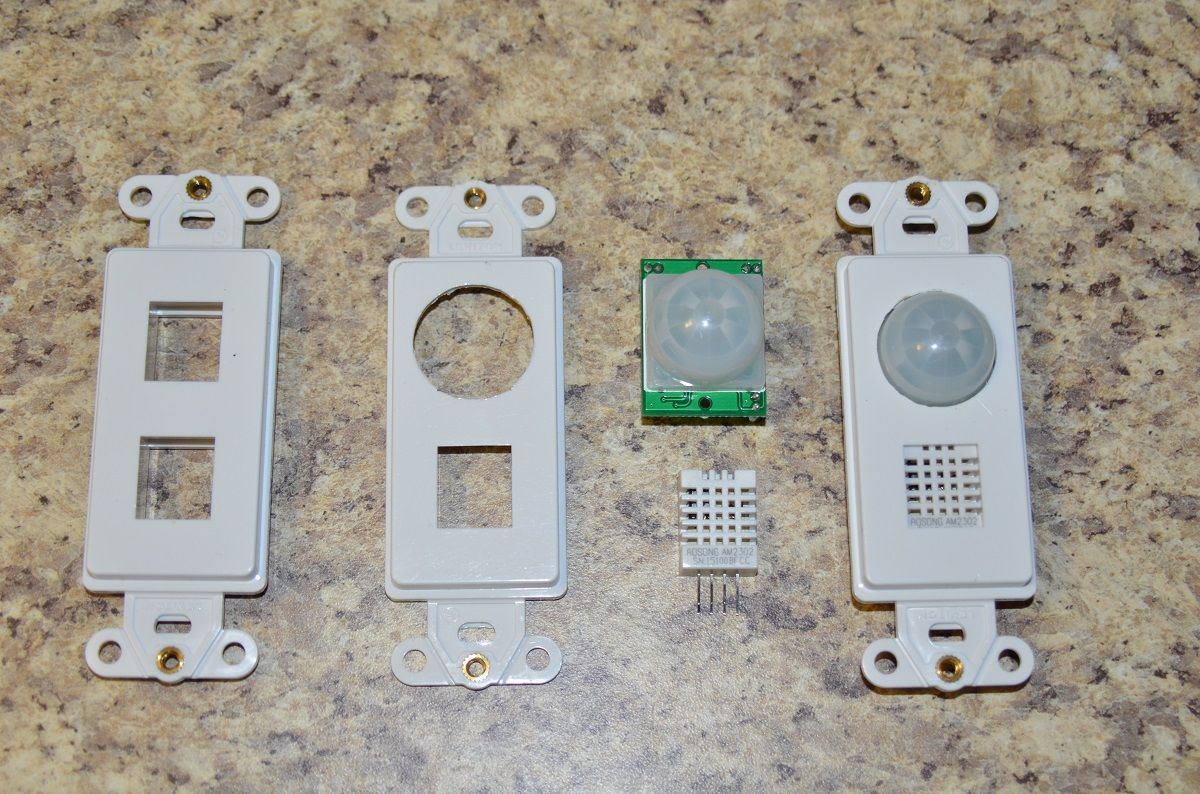
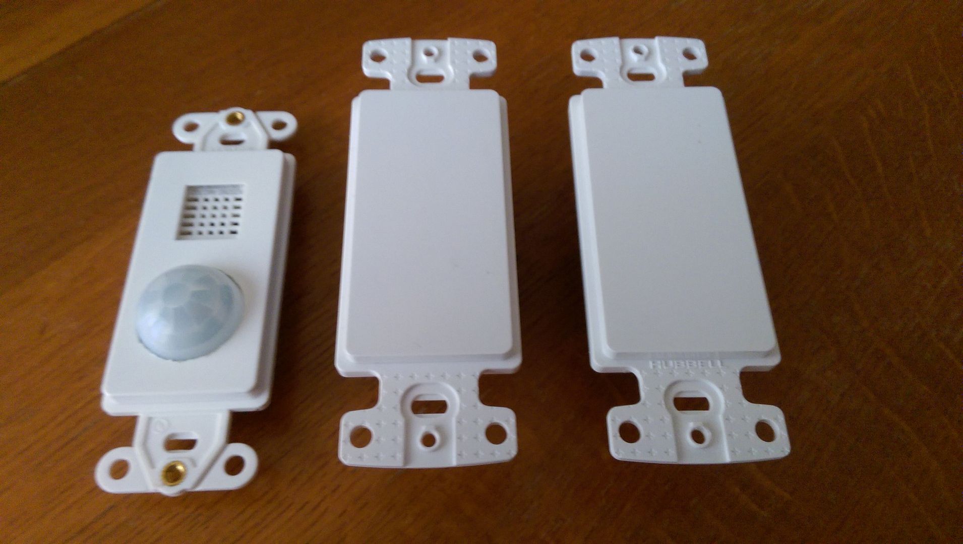
I've now created the sensor plate which can be used with the MySensors Node I developed.
I started with a dual keystone insert plate, the type used for network or cable tv connections. Using some router bits in my bench drill I machined the keystone slots to fit a DHT22 and a motion sensor module.
Bu pure coincidence the DHT22 has the exact same dimensions as the keystone slot at the back of the plate, all it required was machining away some of the height of the slot so the DHT22 sits flush.
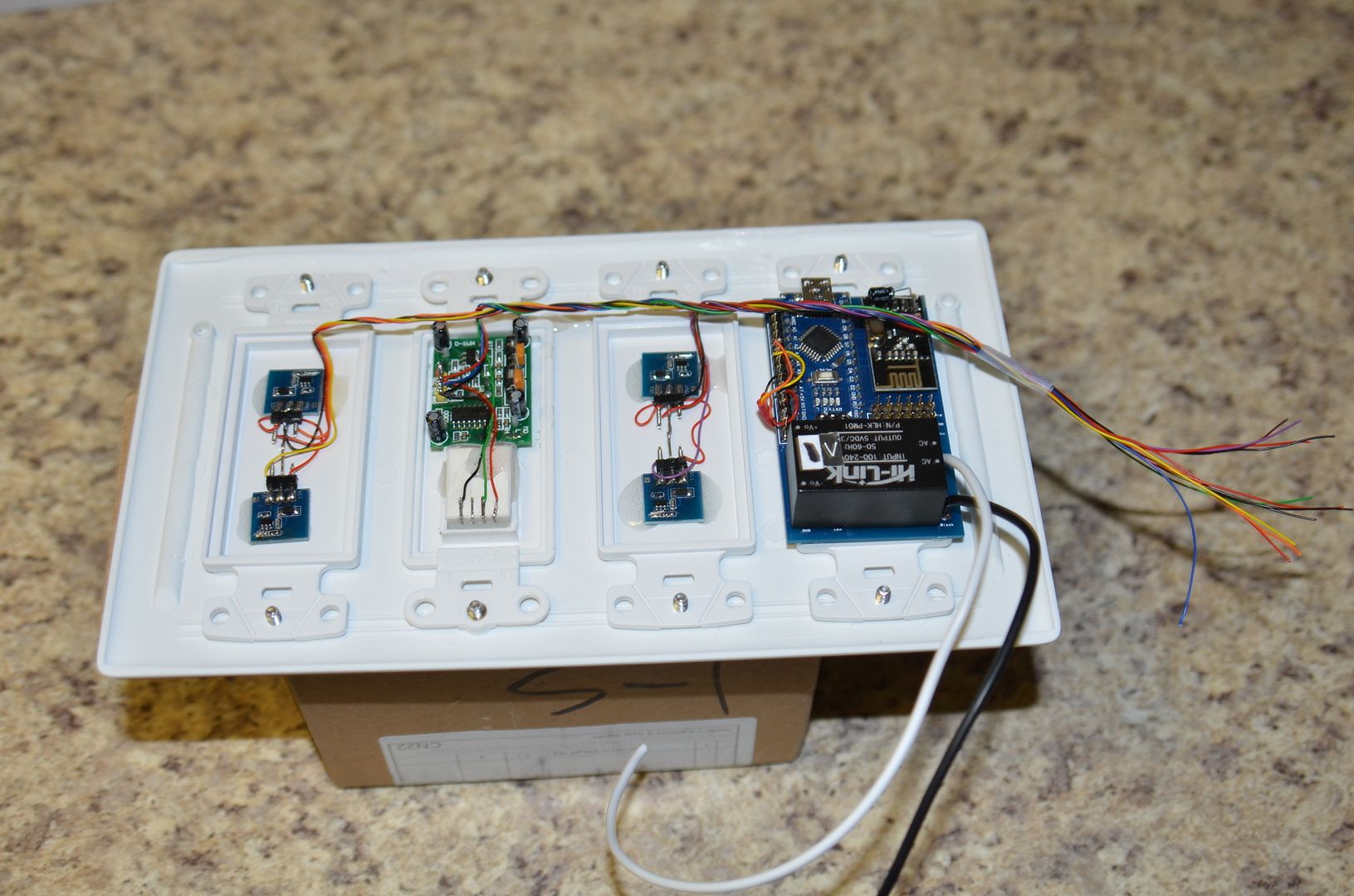
Assembling and wiring the master switch unit. next step is to add the 4 relay units, connect all wires to the node and add the safety cover/joiner to prevent accidental interaction with the 110VAC.
The unit shown will have:
- 4 x touch switch activated relay
- 2 x touch toggle switch (what ever I want them to do in HomeGenie)
- motion sensor
- temperature & humidity
I will share more as this project is moving along.
@enterprised could you share how you connected the touch sensors and how you are reading them? At homegenie you mentioned that you had to change the bridges. The bridges on the buttons I received today are called A and B but I think they correspond to your A and T.
-
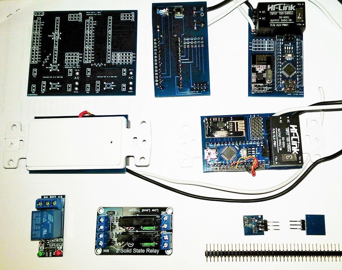
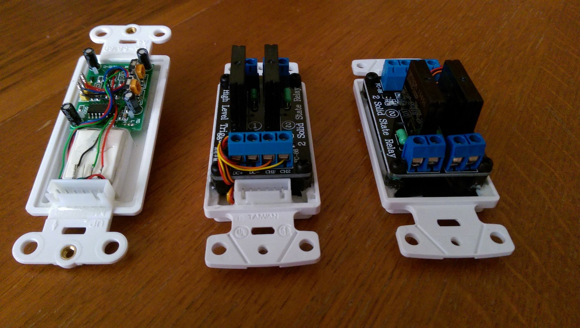
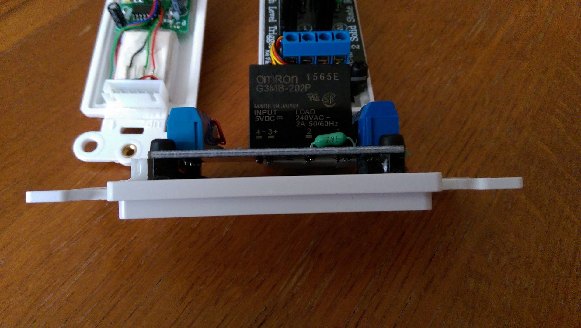
Finally, after some months of extreme travel and work related activity I had some time again to continue with my project.
Below are some pictures of the switch and sensor modules with standardised connection header so I can switch them out and organise them any way I like in my wall switch module/frame.
-
Has anyone looked at putting this on the Vera?
-
Any more work on the project? I really like the concept of this.
-
Any more work on the project? I really like the concept of this.
@csa02221862
Progress is a bit slow, since creating the last batch of various modules work kept me busy travelling again. Just clocked another 26000 miles sitting in planes in the last 3 weeks.I now have the controller modules, sensor and switch modules and all the programming done in mysensors and homegenie.
the last things on my list are sturdy wire-looms to connect it all and protective cover for the controller modules.
Getting close to the point that I will have all main areas of the house connected using these modules.
-
Glad to hear it's coming along. Looking forward to the details, how it's working, board availability, final script, schematics....
Hello! It looks like you're interested in this conversation, but you don't have an account yet.
Getting fed up of having to scroll through the same posts each visit? When you register for an account, you'll always come back to exactly where you were before, and choose to be notified of new replies (either via email, or push notification). You'll also be able to save bookmarks and upvote posts to show your appreciation to other community members.
With your input, this post could be even better 💗
Register Login