Garage door contraption (yet another)


-
Hi Folks
After leaving my garage door open all night for several times, I had to go ahead and make a MySensors contraptions for it.
The garage door system I have has 1 single button it will either open or close the door depending on position, the safety beams and the last operations.
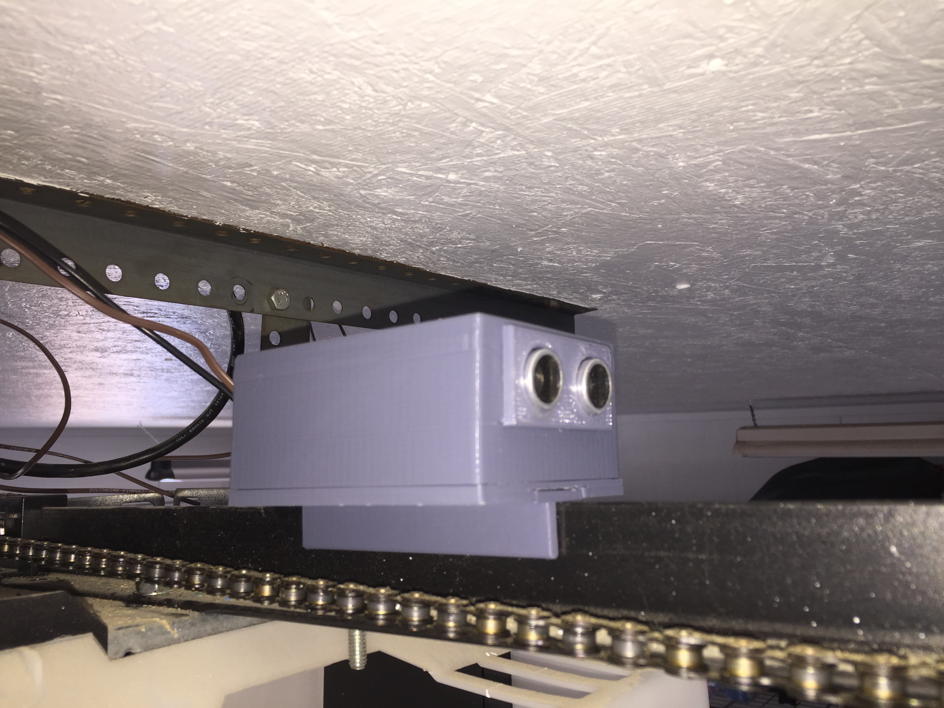
Since I know nothing about electronics, hacking the motor electronics was beyond my skill set, so I decide to sensorize the button operations. In order to figure out if the door was opening or closing I used a sonic distance relative to de door rail. I was expecting to have issues with precision but I was rather surprised it worked so well.
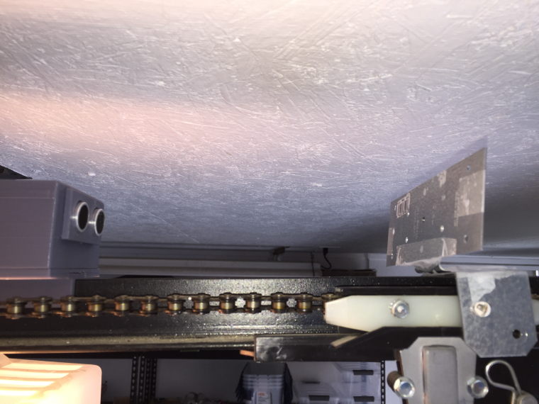
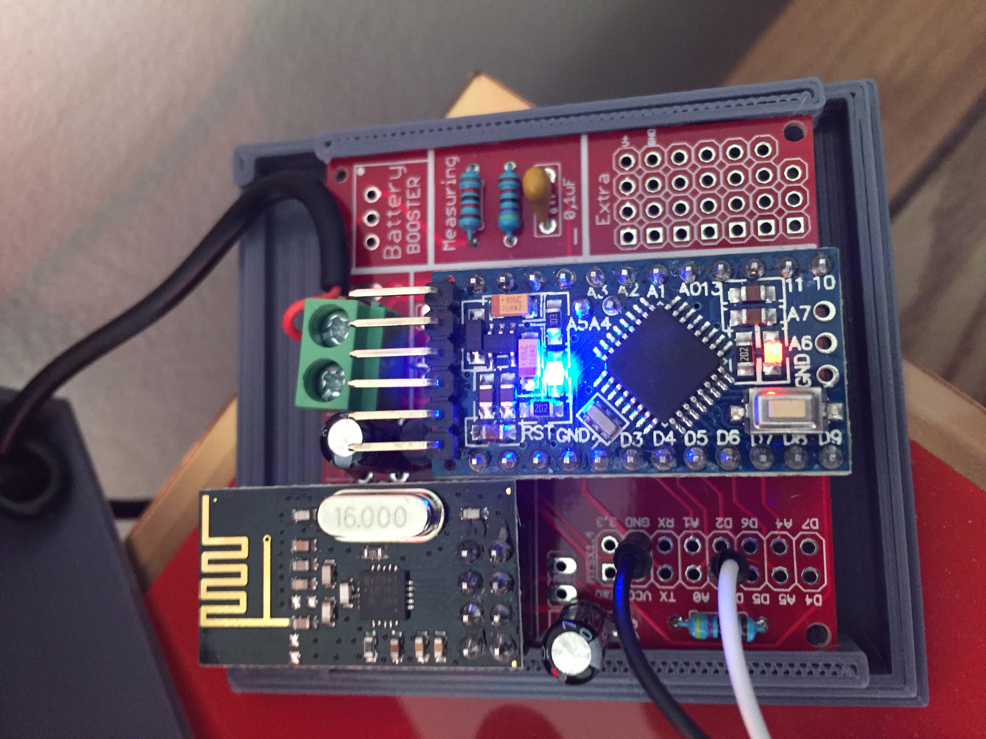
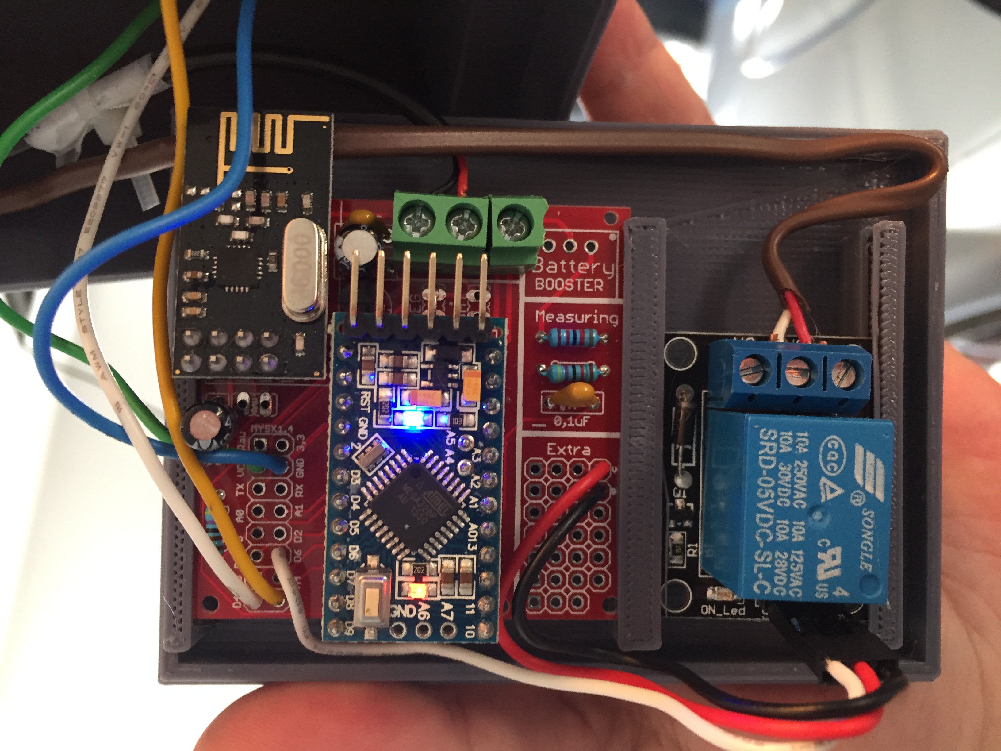
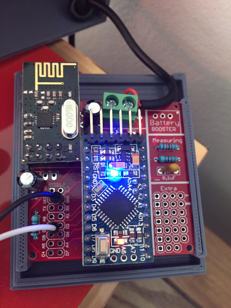
The base is the fantastic Easy/Newbie PCB for MySensors by @sundberg84 with a bumper/box of my own creation.
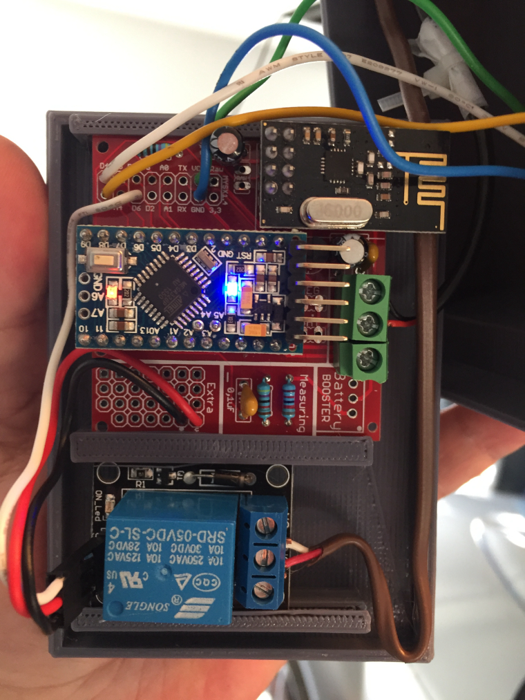
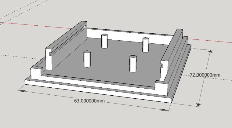
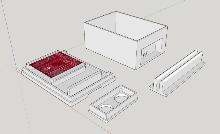
Coupled with some extra pieces as the rail support, the insert for the sonic sensor and the box lid it self.

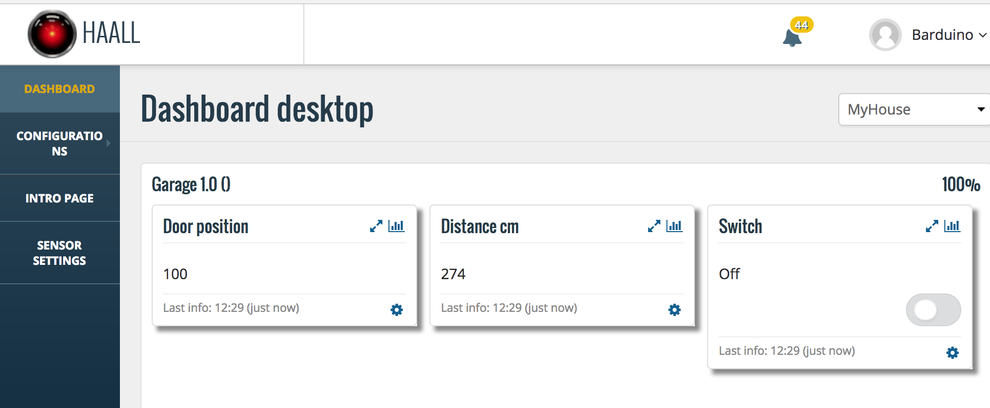
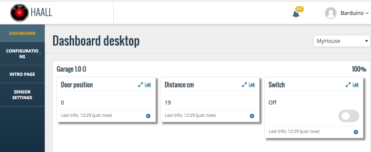
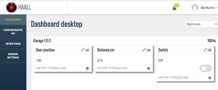
On the controller it looks like this
With door Open
With door Closed
On the other side, I've created a simple led sensor which receives a door open/closed signal directly from the garage sensor to turn on or off a led.
As always feedback is appreciated
Cheers
-
Hi Folks
After leaving my garage door open all night for several times, I had to go ahead and make a MySensors contraptions for it.
The garage door system I have has 1 single button it will either open or close the door depending on position, the safety beams and the last operations.
Since I know nothing about electronics, hacking the motor electronics was beyond my skill set, so I decide to sensorize the button operations. In order to figure out if the door was opening or closing I used a sonic distance relative to de door rail. I was expecting to have issues with precision but I was rather surprised it worked so well.
The base is the fantastic Easy/Newbie PCB for MySensors by @sundberg84 with a bumper/box of my own creation.
Coupled with some extra pieces as the rail support, the insert for the sonic sensor and the box lid it self.
On the controller it looks like this
With door Open
With door Closed
On the other side, I've created a simple led sensor which receives a door open/closed signal directly from the garage sensor to turn on or off a led.
As always feedback is appreciated
Cheers
@barduino Love the enclosure design. I like the way you printed it so that the PCBs slide into the slots. No screws needed. Interesting use of an ultrasonic sensor too. Good job.
I just recently got my 3D printer and I am loving it for my MySensors projects. It's primarily why I bought it though.
-
Hi Folks
After leaving my garage door open all night for several times, I had to go ahead and make a MySensors contraptions for it.
The garage door system I have has 1 single button it will either open or close the door depending on position, the safety beams and the last operations.
Since I know nothing about electronics, hacking the motor electronics was beyond my skill set, so I decide to sensorize the button operations. In order to figure out if the door was opening or closing I used a sonic distance relative to de door rail. I was expecting to have issues with precision but I was rather surprised it worked so well.
The base is the fantastic Easy/Newbie PCB for MySensors by @sundberg84 with a bumper/box of my own creation.
Coupled with some extra pieces as the rail support, the insert for the sonic sensor and the box lid it self.
On the controller it looks like this
With door Open
With door Closed
On the other side, I've created a simple led sensor which receives a door open/closed signal directly from the garage sensor to turn on or off a led.
As always feedback is appreciated
Cheers
-
Yeah, I wanted to know the exact position of the door, if it was opening or closing etc.
Anyway I'll gladly share the 3D files for the Easy board
This is the SketchUp file with the base, rail, lid and enclosure for the sonic.
0_1490732828480_GarageDoorMonitor.zip
And this one the base and lid for the monitor.
The Easy boards I have are v8 and the mounting holes are so small that I couldn't create a support that wouldn't break, so I decided to make some rail/slide system.
Also because I don't solder the Arduino or radio directly to the board, the lid becomes very tall. But its easy to adjust in the 3D files.
If you prefer STL files, I'll upload them
Cheers
-
@barduino Love the enclosure design. I like the way you printed it so that the PCBs slide into the slots. No screws needed. Interesting use of an ultrasonic sensor too. Good job.
I just recently got my 3D printer and I am loving it for my MySensors projects. It's primarily why I bought it though.
-
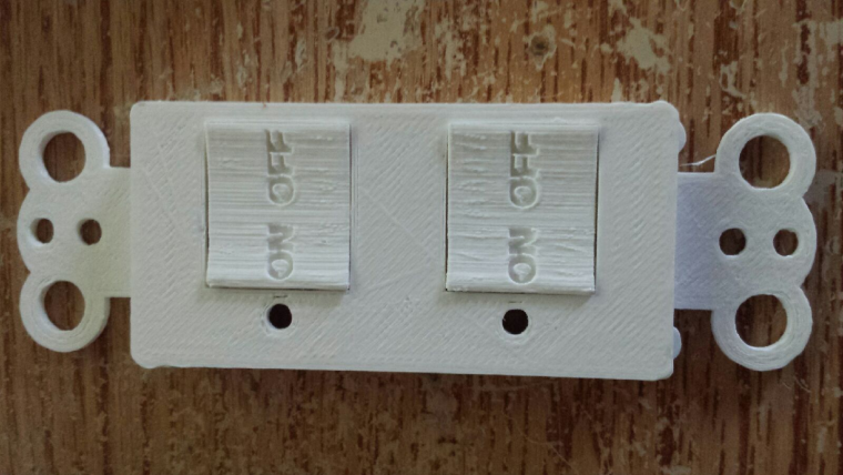
@dbemowsk, I'm very interested in your decora style wall plate, maybe we can compare notes
@barduino Last night I created another decora plate that has 2 bigger switches. I will probably be pushing that one up to my thingiverse account tonight. I have to make the board for it yet, but I think this one will be a bit easier since I only have 4 switches and 2 LEDs to deal with instead of 8 and 4 with the other one.
I also have a project I did with my easy newbie boards where I made an enclosure for my bathroom temp/humidity sensor. Here is the link:
https://forum.mysensors.org/topic/6485/hdc1080-battery-operated-temp-humidity-sensor-with-wall-box
You mentioned that you couldn't create a support that wouldn't break. If you look at the temp/humidity enclosure I just have 4 mounting tabs inside the box. I am using 2mm x 5mm screws to secure it. These are the screws I bought to use on my decora switches. They work great. the tabs are big enough where there is no real chance that they would break. I could possibly get some longer screws because if I screw these in and take them out too much the hole kind of gets stripped. That shouldn't be much of a problem now that I have the enclosure perfected, I shouldn't have a need to remove screws much.Vera Plus running UI7 with MySensors, Sonoffs and 1-Wire devices
Visit my website for more Bits, Bytes and Ramblings from me: http://dan.bemowski.info/ -
@barduino Last night I created another decora plate that has 2 bigger switches. I will probably be pushing that one up to my thingiverse account tonight. I have to make the board for it yet, but I think this one will be a bit easier since I only have 4 switches and 2 LEDs to deal with instead of 8 and 4 with the other one.
I also have a project I did with my easy newbie boards where I made an enclosure for my bathroom temp/humidity sensor. Here is the link:
https://forum.mysensors.org/topic/6485/hdc1080-battery-operated-temp-humidity-sensor-with-wall-box
You mentioned that you couldn't create a support that wouldn't break. If you look at the temp/humidity enclosure I just have 4 mounting tabs inside the box. I am using 2mm x 5mm screws to secure it. These are the screws I bought to use on my decora switches. They work great. the tabs are big enough where there is no real chance that they would break. I could possibly get some longer screws because if I screw these in and take them out too much the hole kind of gets stripped. That shouldn't be much of a problem now that I have the enclosure perfected, I shouldn't have a need to remove screws much.@dbemowsk , the problem is that I lost my screws... (portuguese joke meaning lost my marbles or gone crazy)
Anyway, do you create the threads for the screws in the plastic? or do you use self-threading...
When I do my supports I make them snap-on, like a little wider in the base and then a bit of plastic that goes through the board holes. If the holes are too thin the snap-on bit breaks.
cheers
-
@dbemowsk , the problem is that I lost my screws... (portuguese joke meaning lost my marbles or gone crazy)
Anyway, do you create the threads for the screws in the plastic? or do you use self-threading...
When I do my supports I make them snap-on, like a little wider in the base and then a bit of plastic that goes through the board holes. If the holes are too thin the snap-on bit breaks.
cheers
@barduino I get it, I just have holes that I use self tapping screws in like this style:

I just bought some 2mm x 5mm ones from ebay. As long as you don't torque them in real tight, they hold good. So to hold a circuit board in a box, it is more than enough. -
Yeah, I wanted to know the exact position of the door, if it was opening or closing etc.
Anyway I'll gladly share the 3D files for the Easy board
This is the SketchUp file with the base, rail, lid and enclosure for the sonic.
0_1490732828480_GarageDoorMonitor.zip
And this one the base and lid for the monitor.
The Easy boards I have are v8 and the mounting holes are so small that I couldn't create a support that wouldn't break, so I decided to make some rail/slide system.
Also because I don't solder the Arduino or radio directly to the board, the lid becomes very tall. But its easy to adjust in the 3D files.
If you prefer STL files, I'll upload them
Cheers
-
I had a test setup that also had a sensor looking down so I could 'see' if my car was parked in the garage or not.... if distance < 1m == car parked.
My garage door opener is directly above my car when its parked.
Hello! It looks like you're interested in this conversation, but you don't have an account yet.
Getting fed up of having to scroll through the same posts each visit? When you register for an account, you'll always come back to exactly where you were before, and choose to be notified of new replies (either via email, or push notification). You'll also be able to save bookmarks and upvote posts to show your appreciation to other community members.
With your input, this post could be even better 💗
Register Login