With MySensors PC cold start!
-
Can someone help me or write a sketch?
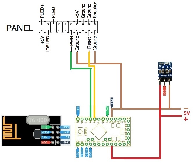
I would like to start my PC using Arduino, shutdown and reset!On a normal PC you connect so only pin against the desired mode.
Pin 1 - mass short passage = PC starts
Pin 1 - Ground Long Pass Approx. 5sec = PC Shuts down
Pin 2 - Ground Short Circuit = PC Reset
A little I have already prepared. I have to search for everything and I do not know the language that way.
Thank you
#define MY_DEBUG #define MY_NODE_ID AUTO #define MY_RADIO_NRF24 #define MY_REPEATER_FEATURE #define PULSE_TIME 500UL // half a second boolean goPulse; unsigned long pulseStartTime; #include <MySensors.h> #define RELAY_PIN_A 4 #define RELAY_PIN_B 5 // Arduino Digital I/O pin number for first relay (second on pin+1 etc) #define NUMBER_OF_RELAYS 2 // Total number of attached relays #define RELAY_ON 1 // GPIO value to write to turn on attached relay #define RELAY_OFF 0 // GPIO value to write to turn off attached relay void before() { for (int sensor=1, pin=RELAY_PIN_A; sensor<=NUMBER_OF_RELAYS; sensor++, pin++) { // Then set relay pins in output mode pinMode(pin, OUTPUT); } for (int sensor=1, pin=RELAY_PIN_B; sensor<=NUMBER_OF_RELAYS; sensor++, pin++) { // Then set relay pins in output mode pinMode(pin, OUTPUT); } } void setup() { } void presentation() { // Send the sketch version information to the gateway and Controller sendSketchInfo("Relay", "1.0"); for (int sensor=1, pin=RELAY_PIN_A; sensor<=NUMBER_OF_RELAYS; sensor++, pin++) { // Register all sensors to gw (they will be created as child devices) present(sensor, S_BINARY); } for (int sensor=1, pin=RELAY_PIN_B; sensor<=NUMBER_OF_RELAYS; sensor++, pin++) { // Register all sensors to gw (they will be created as child devices) present(sensor, S_BINARY); } } void loop() { } void receive(const MyMessage &message) { // We only expect one type of message from controller. But we better check anyway. if (message.type==V_STATUS) { // Change relay state digitalWrite(message.sensor-1+RELAY_PIN_A, message.getBool()?RELAY_ON:RELAY_OFF); goPulse = true; pulseStartTime = millis(); digitalWrite(message.sensor-1+RELAY_PIN_B, message.getBool()?RELAY_ON:RELAY_OFF); // Store state in eeprom saveState(message.sensor, message.getBool()); // Write some debug info Serial.print("Incoming change for sensor:"); Serial.print(message.sensor); Serial.print(", New status: "); Serial.println(message.getBool()); } relayPulse(); } void relayPulse() { if (goPulse) { if (millis() - pulseStartTime < PULSE_TIME) { digitalWrite(RELAY_PIN_A, RELAY_OFF);// didn't know your pin } else { digitalWrite(RELAY_PIN_B, RELAY_OFF); // didn't know your pin goPulse = false; } } } -
The pins on the sketch and the schematic do not match,
You need to be more careful on matching the items as it will make troubleshooting more difficult.This sketch is a quick and dirty method, that does basically to work for me using OpenHAB as a controller. (only tested using LED outputs not with an actual computer).
If i was actually going to implement this, I would monitor the POWER LED on the computer for feedback and control of the pulses. ie for shutdown, try short pulse first for controlled shutdown and if not shutdown within expected time span, then preform a hard shutdown./* * PC Power On/Off & Reset Sketch * Power Pin Pulse = PC Starts if Already Off, *** PC Shutsdown if already on ## this is the operation of my Computer ## * Power Pin 5 Seconds Low = PC Forced Shutdown * Reset Pin Pulse Low = PC Reset (if already on) * * Using three child IDs * 1 = Power On/Off * 2 = Forced OFF * 3 = Reset * * Version 1.0 2018-01-19 */ /** * The MySensors Arduino library handles the wireless radio link and protocol * between your home built sensors/actuators and HA controller of choice. * The sensors forms a self healing radio network with optional repeaters. Each * repeater and gateway builds a routing tables in EEPROM which keeps track of the * network topology allowing messages to be routed to nodes. * * Created by Henrik Ekblad <henrik.ekblad@mysensors.org> * Copyright (C) 2013-2015 Sensnology AB * Full contributor list: https://github.com/mysensors/Arduino/graphs/contributors * * Documentation: http://www.mysensors.org * Support Forum: http://forum.mysensors.org * * This program is free software; you can redistribute it and/or * modify it under the terms of the GNU General Public License * version 2 as published by the Free Software Foundation. * ******************************* * * REVISION HISTORY * Version 1.0 - Henrik Ekblad * * DESCRIPTION * Example sketch showing how to control physical relays. * This example will remember relay state after power failure. * http://www.mysensors.org/build/relay */ // Enable debug prints to serial monitor #define MY_DEBUG //#define MY_NODE_ID AUTO #define MY_NODE_ID 155 // my test Node ID, Comment out for Auto ID // Enable and select radio type attached #define MY_RADIO_NRF24 //#define MY_RADIO_NRF5_ESB //#define MY_RADIO_RFM69 //#define MY_RADIO_RFM95 // Enable repeater functionality for this node #define MY_REPEATER_FEATURE // if you need the repeater function uncomment #include <MySensors.h> // Wait times #define LONG_WAIT 500 #define SHORT_WAIT 50 #define PULSE_TIME 500UL // half a second #define FORCED_TIME 5000UL // 5 seconds boolean goPulse; unsigned long pulseStartTime; #define POWER_PIN 4 // Arduino Digital I/O pin number for PC Power control #define RESET_PIN 5 // Arduino Digital I/O pin number for PC Reset control #define RELAY_ON 1 // GPIO value to write to turn on attached relay #define RELAY_OFF 0 // GPIO value to write to turn off attached relay #define CHILD_ID_POWER 143 // these ID used for my test machine. change to suit ie 1 #define CHILD_ID_FORCEDOFF 144 // change to suit ie 2 #define CHILD_ID_RESET 145 // change to suit ie 3 boolean Status_Power = 0; boolean Status_Forcedoff = 0; boolean Status_Reset = 0; boolean is_Power = 0; boolean is_ForcedOff = 0; boolean is_Reset = 0; // Setup Messages MyMessage msg(CHILD_ID_POWER,V_STATUS); void before() { // Set the pins to output mode pinMode(POWER_PIN, OUTPUT); pinMode(RESET_PIN, OUTPUT); // Set the Pin states to known state digitalWrite(POWER_PIN, RELAY_OFF); digitalWrite(RESET_PIN, RELAY_OFF); } void setup() { } void presentation() { // Send the sketch version information to the gateway and Controller sendSketchInfo("Relay", "1.0"); wait(LONG_WAIT); // Give gateway time to Process // Present child ids to conroller present(CHILD_ID_POWER, S_BINARY, "PC Power on-off"); wait(SHORT_WAIT); // Give gateway time to Process present(CHILD_ID_FORCEDOFF, S_BINARY, "PC Forced off"); wait(SHORT_WAIT); // Give gateway time to Process present(CHILD_ID_RESET, S_BINARY, "PC Reset"); wait(SHORT_WAIT); // Give gateway time to Process } void loop() { Serial.println(); Serial.print ("loop start "); send(msg.setSensor(CHILD_ID_POWER).set( Status_Power)); send(msg.setSensor(CHILD_ID_FORCEDOFF).set( Status_Forcedoff)); send(msg.setSensor(CHILD_ID_RESET).set( Status_Reset)); wait(100000); // wait for testing } void receive(const MyMessage &message) { // We only expect one type of message from controller. But we better check anyway. if (message.type==V_STATUS) switch (message.sensor) { case CHILD_ID_POWER: is_Power = message.getBool(); Serial.print("incoming change for Power:"); Serial.print(message.sensor); Serial.print(", New status: "); Serial.println((is_Power ? "On":"Off")); powercmd(); // process pulses etc in subroutine break; case CHILD_ID_FORCEDOFF: is_ForcedOff = message.getBool(); Serial.print("incoming change for FORCED Power OFF:"); Serial.print(message.sensor); Serial.print(", New status: "); Serial.println((is_ForcedOff ? "On":"Off")); forcedcmd(); break; case CHILD_ID_RESET : is_Reset = message.getBool(); Serial.print("incoming change for Reset:"); Serial.print(message.sensor); Serial.print(", New status: "); Serial.println((is_Reset ? "On":"Off")); resetcmd(); break; default: Serial.print("Unknown/UnImplemented message type: "); Serial.println(message.type); } } void powercmd() { // process power pin if (is_Power != Status_Power) { digitalWrite(POWER_PIN, RELAY_ON); delay(PULSE_TIME); // delay used as pulse time is short & multiple processes are not expected digitalWrite(POWER_PIN, RELAY_OFF); Status_Power = is_Power; } } void forcedcmd() { // process forced power off command if (is_ForcedOff = 1 ) { digitalWrite(POWER_PIN, RELAY_ON); delay(FORCED_TIME); // delay used as multiple processes are not expected, quick and dirty digitalWrite(POWER_PIN, RELAY_OFF); Status_Forcedoff = 0; // reset status for next time Status_Power = 0; // power status also reset if power shutoff } } void resetcmd() { // process reset command if (is_Reset != 1 ) { digitalWrite(RESET_PIN, RELAY_ON); delay(PULSE_TIME); // delay used as multiple processes are not expected, quick and dirty digitalWrite(RESET_PIN, RELAY_OFF); Status_Reset = 0; } } -
Yoy need to have two = in the code
if (is_Reset == 1 )
Hello! It looks like you're interested in this conversation, but you don't have an account yet.
Getting fed up of having to scroll through the same posts each visit? When you register for an account, you'll always come back to exactly where you were before, and choose to be notified of new replies (either via email, or push notification). You'll also be able to save bookmarks and upvote posts to show your appreciation to other community members.
With your input, this post could be even better 💗
Register Login