RFM95 network problem (RPI & Arduino GW)
-
Hi all,
I am new to MySensors and I have tried to set up a GW with a Sensor to establish communication among the two without success.
I am using Adafruit RFM95 modules ( https://www.adafruit.com/product/3072 ) which I have managed to use with RadioHead library (so i know both modules are functional).
Trying to move over to MySensors, I initially tried to set up a Raspberry Pi Gateway following all the steps of the tutorial, on a serial gw, which (at least and according to the debug info was successful as suggested by the tutorial) and then connected an Arduino Uno according to https://www.mysensors.org/build/connect_radio#rfm6995-&-arduino , using the unmodified example of Mysensors (PingPongSensor as well as a few others).
Notice that i have been using unmodified (default) options, aka. only turning on the RF95 option (through the ./configure on RPi and #define MY_RADIO_RFM95 on arduino, an leaving everything else to its defaults.
My Sensor verbose on the serial is :
| / |_ / | ___ _ __ ___ ___ _ __ ___
| |/| | | | _ \ / _ \_ \/ __|/ _ \|_/ __|
| | | | || || | / | | _ \ _ | | _
|| ||_, |/ ___|| ||/_/|| |/
|__/ 2.3.016 MCO:BGN:INIT NODE,CP=RLNNA---,VER=2.3.0
25 TSM:INIT
26 TSF:WUR:MS=0
28 RFM95:INIT
34 RFM95:INIT:PIN,CS=10,IQP=2,IQN=0,RST=5
49 RFM95:PTX:LEVEL=13
51 TSM:INIT:TSP OK
52 TSM:FPAR
53 RFM95:SWR:SEND,TO=255,SEQ=0,RETRY=0
105 TSF:MSG:SEND,255-255-255-255,s=255,c=3,t=7,pt=0,l=0,sg=0,ft=0,st=OK:
2113 !TSM:FPAR:NO REPLY
2115 TSM:FPAR
2116 RFM95:SWR:SEND,TO=255,SEQ=1,RETRY=0
2168 TSF:MSG:SEND,255-255-255-255,s=255,c=3,t=7,pt=0,l=0,sg=0,ft=0,st=OK:
4177 !TSM:FPAR:NO REPLY
4179 TSM:FPAR
4180 RFM95:SWR:SEND,TO=255,SEQ=2,RETRY=0
4233 TSF:MSG:SEND,255-255-255-255,s=255,c=3,t=7,pt=0,l=0,sg=0,ft=0,st=OK:
6241 !TSM:FPAR:NO REPLY
6243 TSM:FPAR
6244 RFM95:SWR:SEND,TO=255,SEQ=3,RETRY=0
6296 TSF:MSG:SEND,255-255-255-255,s=255,c=3,t=7,pt=0,l=0,sg=0,ft=0,st=OK:
8304 !TSM:FPAR:FAIL
8305 TSM:FAIL:CNT=1
8307 TSM:FAIL:DIS
8309 TSF:TDI:TSL
8310 RFM95:RSL
18313 TSM:FAIL:RE-INIT
18315 TSM:INIT
18316 RFM95:INIT
18323 RFM95:INIT:PIN,CS=10,IQP=2,IQN=0,RST=5
18337 RFM95:PTX:LEVEL=13
18339 TSM:INIT:TSP OK
18341 TSM:FPAR
18342 RFM95:SWR:SEND,TO=255,SEQ=0,RETRY=0
18396 TSF:MSG:SEND,255-255-255-255,s=255,c=3,t=7,pt=0,l=0,sg=0,ft=0,st=OK:
20403 !TSM:FPAR:NO REPLY
20405 TSM:FPAR.... (and so on)
Apparently, the FPAR fails, so after digging a bit on the forums, people suggested that there is no communication with the GW. In order to avoid having a defective configuration on the gw, i tried to set up a serial gateway on a 2nd Arduino. Again, i got successful verbose :
0;255;3;0;9;0 MCO:BGN:INIT GW,CP=RLNGA---,VER=2.3.0
0;255;3;0;9;4 TSM:INIT
0;255;3;0;9;6 TSF:WUR:MS=0
0;255;3;0;9;18 TSM:INIT:TSP OK
0;255;3;0;9;21 TSM:INIT:GW MODE
0;255;3;0;9;24 TSM:READY:ID=0,PAR=0,DIS=0
0;255;3;0;9;28 MCO:REG:NOT NEEDED
0;255;3;0;14;Gateway startup complete.
0;255;0;0;18;2.3.0
0;255;3;0;9;32 MCO:BGN:STP
0;255;3;0;9;38 MCO:BGN:INIT OK,TSP=1And the GW get no recv messages.
In all my cases the sketches are the default ones, with the only change of:
#define MY_RADIO_RFM95
#define MY_DEBUG_VERBOSE_RFM95(similarly was in the RPi Gateway)
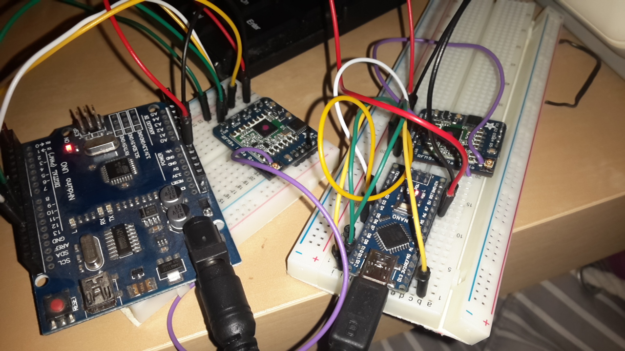
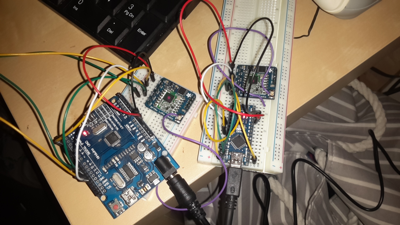
I am also attaching 2 photos of my arduino wirings with the LoRA modules:
 image url)
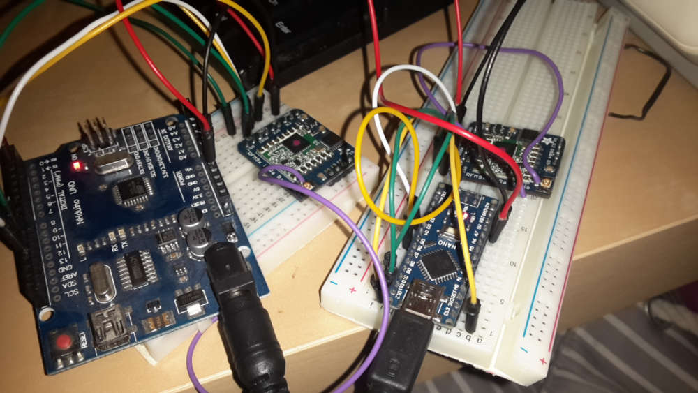
I have tried to move on with this communication a few days now and have reached a point where I dont know what to try next. Please suggest where would the problem lie in.
Thank you in advance
-
Hi all,
I am new to MySensors and I have tried to set up a GW with a Sensor to establish communication among the two without success.
I am using Adafruit RFM95 modules ( https://www.adafruit.com/product/3072 ) which I have managed to use with RadioHead library (so i know both modules are functional).
Trying to move over to MySensors, I initially tried to set up a Raspberry Pi Gateway following all the steps of the tutorial, on a serial gw, which (at least and according to the debug info was successful as suggested by the tutorial) and then connected an Arduino Uno according to https://www.mysensors.org/build/connect_radio#rfm6995-&-arduino , using the unmodified example of Mysensors (PingPongSensor as well as a few others).
Notice that i have been using unmodified (default) options, aka. only turning on the RF95 option (through the ./configure on RPi and #define MY_RADIO_RFM95 on arduino, an leaving everything else to its defaults.
My Sensor verbose on the serial is :
| / |_ / | ___ _ __ ___ ___ _ __ ___
| |/| | | | _ \ / _ \_ \/ __|/ _ \|_/ __|
| | | | || || | / | | _ \ _ | | _
|| ||_, |/ ___|| ||/_/|| |/
|__/ 2.3.016 MCO:BGN:INIT NODE,CP=RLNNA---,VER=2.3.0
25 TSM:INIT
26 TSF:WUR:MS=0
28 RFM95:INIT
34 RFM95:INIT:PIN,CS=10,IQP=2,IQN=0,RST=5
49 RFM95:PTX:LEVEL=13
51 TSM:INIT:TSP OK
52 TSM:FPAR
53 RFM95:SWR:SEND,TO=255,SEQ=0,RETRY=0
105 TSF:MSG:SEND,255-255-255-255,s=255,c=3,t=7,pt=0,l=0,sg=0,ft=0,st=OK:
2113 !TSM:FPAR:NO REPLY
2115 TSM:FPAR
2116 RFM95:SWR:SEND,TO=255,SEQ=1,RETRY=0
2168 TSF:MSG:SEND,255-255-255-255,s=255,c=3,t=7,pt=0,l=0,sg=0,ft=0,st=OK:
4177 !TSM:FPAR:NO REPLY
4179 TSM:FPAR
4180 RFM95:SWR:SEND,TO=255,SEQ=2,RETRY=0
4233 TSF:MSG:SEND,255-255-255-255,s=255,c=3,t=7,pt=0,l=0,sg=0,ft=0,st=OK:
6241 !TSM:FPAR:NO REPLY
6243 TSM:FPAR
6244 RFM95:SWR:SEND,TO=255,SEQ=3,RETRY=0
6296 TSF:MSG:SEND,255-255-255-255,s=255,c=3,t=7,pt=0,l=0,sg=0,ft=0,st=OK:
8304 !TSM:FPAR:FAIL
8305 TSM:FAIL:CNT=1
8307 TSM:FAIL:DIS
8309 TSF:TDI:TSL
8310 RFM95:RSL
18313 TSM:FAIL:RE-INIT
18315 TSM:INIT
18316 RFM95:INIT
18323 RFM95:INIT:PIN,CS=10,IQP=2,IQN=0,RST=5
18337 RFM95:PTX:LEVEL=13
18339 TSM:INIT:TSP OK
18341 TSM:FPAR
18342 RFM95:SWR:SEND,TO=255,SEQ=0,RETRY=0
18396 TSF:MSG:SEND,255-255-255-255,s=255,c=3,t=7,pt=0,l=0,sg=0,ft=0,st=OK:
20403 !TSM:FPAR:NO REPLY
20405 TSM:FPAR.... (and so on)
Apparently, the FPAR fails, so after digging a bit on the forums, people suggested that there is no communication with the GW. In order to avoid having a defective configuration on the gw, i tried to set up a serial gateway on a 2nd Arduino. Again, i got successful verbose :
0;255;3;0;9;0 MCO:BGN:INIT GW,CP=RLNGA---,VER=2.3.0
0;255;3;0;9;4 TSM:INIT
0;255;3;0;9;6 TSF:WUR:MS=0
0;255;3;0;9;18 TSM:INIT:TSP OK
0;255;3;0;9;21 TSM:INIT:GW MODE
0;255;3;0;9;24 TSM:READY:ID=0,PAR=0,DIS=0
0;255;3;0;9;28 MCO:REG:NOT NEEDED
0;255;3;0;14;Gateway startup complete.
0;255;0;0;18;2.3.0
0;255;3;0;9;32 MCO:BGN:STP
0;255;3;0;9;38 MCO:BGN:INIT OK,TSP=1And the GW get no recv messages.
In all my cases the sketches are the default ones, with the only change of:
#define MY_RADIO_RFM95
#define MY_DEBUG_VERBOSE_RFM95(similarly was in the RPi Gateway)
I am also attaching 2 photos of my arduino wirings with the LoRA modules:
I have tried to move on with this communication a few days now and have reached a point where I dont know what to try next. Please suggest where would the problem lie in.
Thank you in advance
@m3nt4lll Try to assign a fixed node ID to your sensors nodes with the line:
#define MY_NODE_ID 12Change the number to what you like.
I also had the same problem with a serial gateway with RFM69 and a simple temp+hum node. They did startup ok but no communication between them.
I then assigned a node ID to the sensor node and oddly it worked…Other thing i noticed is that im not getting internal messages delivered to the gateway, only sensor values defined by MyMessage and presented.
The sketch info sent with sendSketchInfo doesnt show on Domoticz side, neither does battery levels sent with sendBatteryLevel. If i just change the radio to a NRF24 with the same sketch code, everything works…
@m3nt4lll If you get communication, see if you have this problem too.I wonder if this has anything to do with Ack collision discussed here ? It seems the fix suggested by @Koresh didt get implemented yet…
Any ideias guys?
-
Hi all,
I am new to MySensors and I have tried to set up a GW with a Sensor to establish communication among the two without success.
I am using Adafruit RFM95 modules ( https://www.adafruit.com/product/3072 ) which I have managed to use with RadioHead library (so i know both modules are functional).
Trying to move over to MySensors, I initially tried to set up a Raspberry Pi Gateway following all the steps of the tutorial, on a serial gw, which (at least and according to the debug info was successful as suggested by the tutorial) and then connected an Arduino Uno according to https://www.mysensors.org/build/connect_radio#rfm6995-&-arduino , using the unmodified example of Mysensors (PingPongSensor as well as a few others).
Notice that i have been using unmodified (default) options, aka. only turning on the RF95 option (through the ./configure on RPi and #define MY_RADIO_RFM95 on arduino, an leaving everything else to its defaults.
My Sensor verbose on the serial is :
| / |_ / | ___ _ __ ___ ___ _ __ ___
| |/| | | | _ \ / _ \_ \/ __|/ _ \|_/ __|
| | | | || || | / | | _ \ _ | | _
|| ||_, |/ ___|| ||/_/|| |/
|__/ 2.3.016 MCO:BGN:INIT NODE,CP=RLNNA---,VER=2.3.0
25 TSM:INIT
26 TSF:WUR:MS=0
28 RFM95:INIT
34 RFM95:INIT:PIN,CS=10,IQP=2,IQN=0,RST=5
49 RFM95:PTX:LEVEL=13
51 TSM:INIT:TSP OK
52 TSM:FPAR
53 RFM95:SWR:SEND,TO=255,SEQ=0,RETRY=0
105 TSF:MSG:SEND,255-255-255-255,s=255,c=3,t=7,pt=0,l=0,sg=0,ft=0,st=OK:
2113 !TSM:FPAR:NO REPLY
2115 TSM:FPAR
2116 RFM95:SWR:SEND,TO=255,SEQ=1,RETRY=0
2168 TSF:MSG:SEND,255-255-255-255,s=255,c=3,t=7,pt=0,l=0,sg=0,ft=0,st=OK:
4177 !TSM:FPAR:NO REPLY
4179 TSM:FPAR
4180 RFM95:SWR:SEND,TO=255,SEQ=2,RETRY=0
4233 TSF:MSG:SEND,255-255-255-255,s=255,c=3,t=7,pt=0,l=0,sg=0,ft=0,st=OK:
6241 !TSM:FPAR:NO REPLY
6243 TSM:FPAR
6244 RFM95:SWR:SEND,TO=255,SEQ=3,RETRY=0
6296 TSF:MSG:SEND,255-255-255-255,s=255,c=3,t=7,pt=0,l=0,sg=0,ft=0,st=OK:
8304 !TSM:FPAR:FAIL
8305 TSM:FAIL:CNT=1
8307 TSM:FAIL:DIS
8309 TSF:TDI:TSL
8310 RFM95:RSL
18313 TSM:FAIL:RE-INIT
18315 TSM:INIT
18316 RFM95:INIT
18323 RFM95:INIT:PIN,CS=10,IQP=2,IQN=0,RST=5
18337 RFM95:PTX:LEVEL=13
18339 TSM:INIT:TSP OK
18341 TSM:FPAR
18342 RFM95:SWR:SEND,TO=255,SEQ=0,RETRY=0
18396 TSF:MSG:SEND,255-255-255-255,s=255,c=3,t=7,pt=0,l=0,sg=0,ft=0,st=OK:
20403 !TSM:FPAR:NO REPLY
20405 TSM:FPAR.... (and so on)
Apparently, the FPAR fails, so after digging a bit on the forums, people suggested that there is no communication with the GW. In order to avoid having a defective configuration on the gw, i tried to set up a serial gateway on a 2nd Arduino. Again, i got successful verbose :
0;255;3;0;9;0 MCO:BGN:INIT GW,CP=RLNGA---,VER=2.3.0
0;255;3;0;9;4 TSM:INIT
0;255;3;0;9;6 TSF:WUR:MS=0
0;255;3;0;9;18 TSM:INIT:TSP OK
0;255;3;0;9;21 TSM:INIT:GW MODE
0;255;3;0;9;24 TSM:READY:ID=0,PAR=0,DIS=0
0;255;3;0;9;28 MCO:REG:NOT NEEDED
0;255;3;0;14;Gateway startup complete.
0;255;0;0;18;2.3.0
0;255;3;0;9;32 MCO:BGN:STP
0;255;3;0;9;38 MCO:BGN:INIT OK,TSP=1And the GW get no recv messages.
In all my cases the sketches are the default ones, with the only change of:
#define MY_RADIO_RFM95
#define MY_DEBUG_VERBOSE_RFM95(similarly was in the RPi Gateway)
I am also attaching 2 photos of my arduino wirings with the LoRA modules:
I have tried to move on with this communication a few days now and have reached a point where I dont know what to try next. Please suggest where would the problem lie in.
Thank you in advance
-
Hi Both and thanks for your replies.
@titvs I have tried also to assign NODE ID, but without luck. I will try again once i get back to it (i m currently at work so cannot test). EDIT The modules are connected on IRQ pin 2
@tekka Good point. I noticed that the module i use states : 433 MHz only. At some point i did set the frequency to ( #define RFM95_434MHZ ) but i m not sure if i did with the Examples, will certainly give that a shot (i remember i removed to reduce my customisation).
The #define RFM95_434MHZ should be equivalent with what is stated as 433 MHz, right? Could there be a problem?My apologies, the correct module is : https://www.adafruit.com/product/3073 (and not 3072 as i wrote on my initial post )
Thank you, I will come with an update later today
-
Hi @mfalkvidd , 433 is not defined anywhere (also if you check the link you sent).
Instead, in https://github.com/mysensors/MySensors/blob/master/drivers/RFM95/RFM95.h you can see that the pre-defined symbols are:
// Frequency definitions
#define RFM95_169MHZ (169000000ul) //!< 169 Mhz
#define RFM95_315MHZ (315000000ul) //!< 315 Mhz
#define RFM95_434MHZ (433920000ul) //!< 433.92 Mhz
#define RFM95_868MHZ (868100000ul) //!< 868.1 Mhz
#define RFM95_915MHZ (915000000ul) //!< 915 MhzI assume I can override that by setting
#define MY_RFM95_FREQUENCY (433000000ul)but i also guess that these pre-defined are standards to most hardware devices.
Anyway I will come back once i test these -
Alright,
Sometimes the solution is pretty obvious but you fail to spot it.
@tekka thanks for pointing me to the correct direction, as the problem was in the used frequency.Even though I initially tried with 434 MHz, it turns out that when i finally did it right, i had already switched to the default 868.
After adding
#define MY_RFM95_FREQUENCY RFM95_434MHZ
in the sketches initially, i established communication.After that i also tried to configure again the rasperry (this time knowing that the node is working) and Hooray! it worked :)
Thank you all for your support and @titvs @mfalkvidd as well.
This topic can now be locked
Hello! It looks like you're interested in this conversation, but you don't have an account yet.
Getting fed up of having to scroll through the same posts each visit? When you register for an account, you'll always come back to exactly where you were before, and choose to be notified of new replies (either via email, or push notification). You'll also be able to save bookmarks and upvote posts to show your appreciation to other community members.
With your input, this post could be even better 💗
Register Login