Candle - signal Hub - A universal 433Mhz signal detector and cloner


  • Plugin Developer

    It took three weeks to build, but here it is: a device that will easily connect almost any 433Mhz device to your smart home.

    The 433 Hub can do two things:

    • You can teach it a signal, and from then on it will be able to detect it.
    • You can teach it a signal, and from then on it will be able to replay it.

    Both of these features come in 'single signal' and 'on+off" versions. So for example:

    • You could copy the ON and OFF button from a remote for your 433Mhz sockets, and from then on switch the socket from your smart home controller.
    • You could teach it to detect window sensors that have both on and off states.
    • You could teach it to detect the alarm signal from a wireless smoke detector.

    For each signal that you teach it to recognise, a door sensor will be presented to your controller.
    For each signal that you teach it to replay, an on/off switch will be presented to your controller.

    Signals take between 8 and 28 bytes to store, depending on complexity and if they are simple or on+off signals. This means an Arduino Nano can store between 20 and 60 signals in just half of it's eeprom (512 bytes).

    HARDWARE

    • Arduino

    • 433Mhz receiver & transmitter

    • Touch screen (optional, recommended)
      or

    • OLED screen (optional)

    • Keypad (optional)

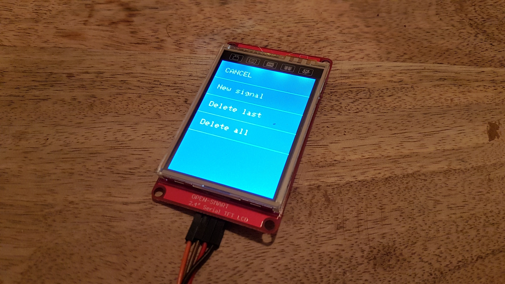
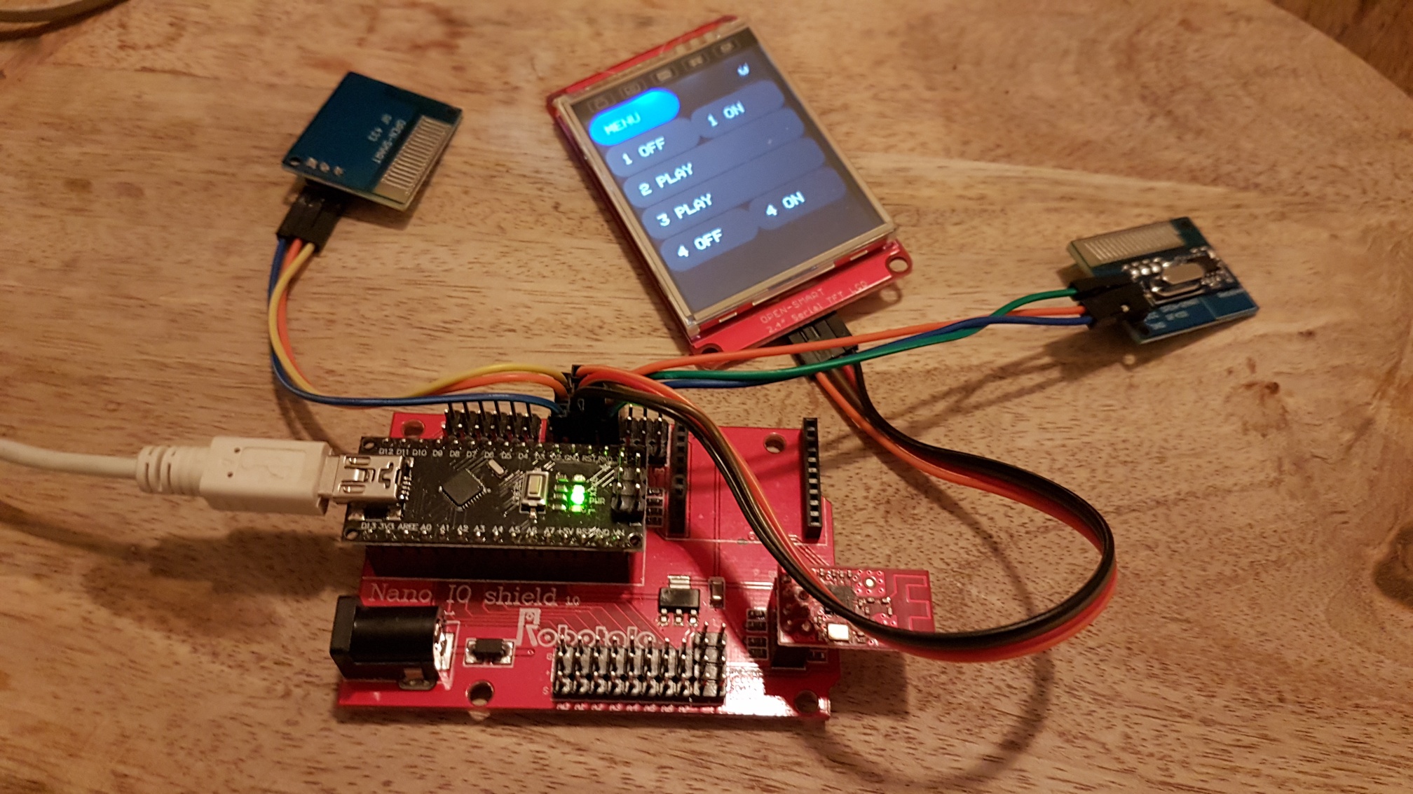
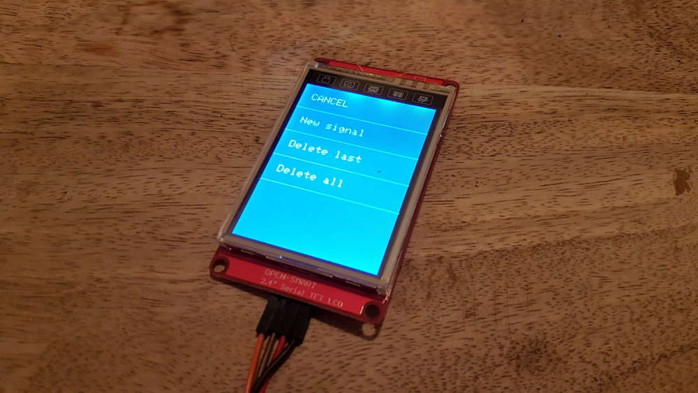
    Here's the version that uses a touch screen.
    0_1551117671838_20190218_220842_resized.jpg
    0_1551117742127_20190218_220924_resized.jpg

    Here's a version that uses a keypad.
    0_1547905513000_433hub-lowres.jpg
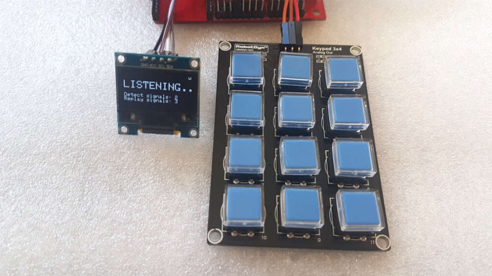
    With a 12 button keypad you can easily replay 10 signals. The last two buttons are used to navigate and make selections in the menu system.

    You can also trigger the learning sequences from 4 virtual buttons that the device creates on your controller (detect simple, detect on+off, replay simple, replay on+off).

    It works best if you use the touch screen. Using the menu you can delete the last recorded signal, or delete all recorded signals.

    It's designed to work with the upcoming Candle privacy friendly smart home, and the Candle Manager. More on that later this year.

    CODE
    https://github.com/createcandle/Devices/blob/master/Signal-hub/Signal-hub.ino


  • @alowhum So this can act as a kind of learning remote, correct?

    Nice work by the way.


  • Plugin Developer

    Exactly.

    And a learning detector at the same time.


  • Plugin Developer

    The touch screen code is now also available.


  • Plugin Developer

    Something I had hoped actually works: it can also copy IR (infrared) signals!

    Settings need to be slightly different, as IR signals are 'slower' than RF signals. Changes I made to the settings are:

    #define MAXEDGES 100            // instead of 400                    
    #define GRANULARITY 100       // the default settings of '50' also work, but IR signals need less precision.
    #define MAXIMUMDURATION 66000
    #define MINIMUMSILENCE 66000
    

    It doesn't recognise things perfectly, as IR signals don't seem to repeat themselves in the same way. You may have to press the button a few times before the signal can be copied.

    I also haven't tested if transmitting the signals actually switches IR devices on and off.

    An example:

    00000000 > 0
    11110111 > 239
    00010000 > 8
    11101111 > 247
    

  • Plugin Developer

    • It can now handle even more 433 signals.
    • Slight code simplification


  • Probably a bit of a noob question, but if I don't have any of the optional items, can I still use this? Will it just save the RF commands until it can't save anymore?


  • Plugin Developer

    @Homer yes


  • @alowhum said in Candle - signal Hub - A universal 433Mhz signal detector and cloner:

    @Homer yes

    Thanks, and thanks for your private messages!

    I managed to build a rf433 sender which is connected to wifi and is outside of the Mysensors environment, and it works, but I can't get my controller (Vera) to communicate with it. This looks like it should work perfectly for what I want it to do!

    Thanks for sharing!


  • I am having issues with the device I made myself which doesn't use this code, so I have decided to give this project a go. One problem though... I copied the sketch from you link, and even without any changes or alterations, the sketch doesn't compile. It gets to line 468 and says "detectedMessage" was not declared in this scope.


  • Please ignore the above.... I don't know why but I just tried it again and it compiled immediately.


  • I just worked out what I did! I had commented that I didn't have a touchsceen and that caused the error. I thought I should do this as I don't have one, but I guess I'll have a go at uploading the sketch as it is.


  • Plugin Developer

    Thanks for the feedback. Let me know if you have any issues and I can try to fix them.


  • @alowhum I've finished building this. I have also bought a couple cheap window/door sensors to try, but I've hit a snag.

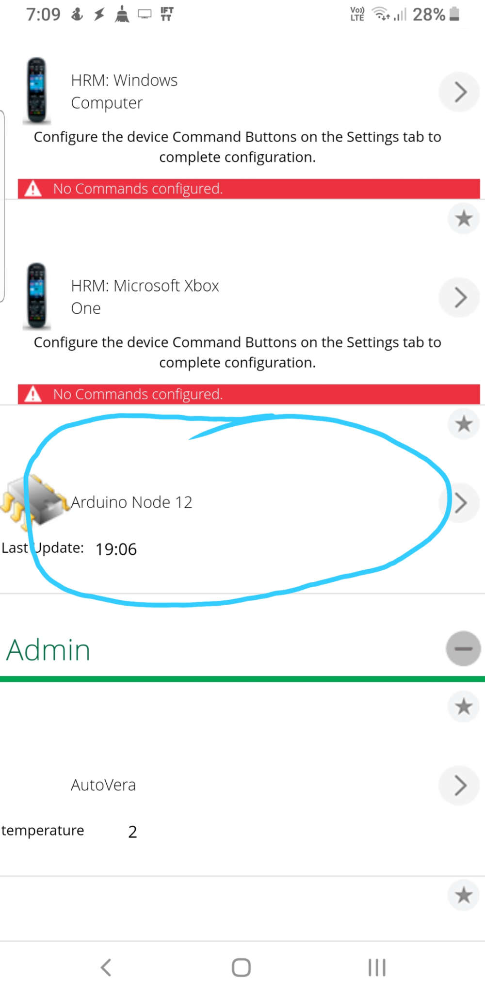
    When I joined this to my controller (Vera) it said that it found 2 devices, but when I check my devices I only find one device, and all it says is that it's a node; I have very little in the way of interacting with it. I'm not sure what's going on.... It's weird that it found two devices and only displays one! Seeing that I'm not using any screen, I can't do anything because I thought I could interact with the hub from within my controller. Have I done something wrong?


  • Plugin Developer

    I haven't tested it without a screen myself. I'll look into it for you and see if I can make the code work optimally without it. I'll get back to you with the updated code.


  • Awesome, thanks!!!


  • Plugin Developer

    Here is the new version which should work just fine without a touchscreen attached.

    https://github.com/createcandle/Devices/blob/master/Signal-hub/Signal-hub.ino

    I also added a new playlist feature. If multiple replay requests are received in quick succession (perhaps from a home automation rule that wants to trigger multiple sockets), it can remember these requests and replay them one after the other.


  • Awesome, thanks for your work! I'll be giving this a go today.

    The extra feature of it remembering if multiple commands are given is great too!


  • I've finally finished building this, but sadly it doesn't want to work with my controller (Vera). When I start the inclusion process I'm says that it has found 2 devices, but when the controller finishes setting it up it only ends up showing one device, and all it says is that it is a node.

    0_1560159136451_Screenshot_20190610-193129_Photos.jpg

    Has anyone built this and have had success with Vera? If you are using this, which controller do you use?


  • Plugin Developer

    It should not show a temperature sensor, since it doesn't have one. Are you sure it has actually connected? Try listening to the serial output of the node (using the Arduino IDE's option to do this), and check if it says that it has connected ok, and that is is showing you the decoded signals then you play the RF signal. You can even try enabling the debug option to get even more details about the node's state.


  • Thanks for the reply!

    It doesn't show a temp sensor. I circled the device that it shows, but of course I only circled one because the second device doesn't show.


  • @homer Look at your device list on a computer web browser. It appears that you are viewing it with the Vera app on your phone or tablet. I have seen where some devices don't show correctly on the Vera app. I don't know what type of device it will identify as, but you should see "<some device type> (12)" with the key being the (12) as that identifies the node that presented it. Also, do you have any 433Mhz devices that it may be detecting? Looking at the code a bit, it looks like it will present any 433Mhz devices that it sees to your Vera controller.


  • @dbemowsk thanks for your reply. Yes the screenshot was taken Vera using my phone, but I only did that as I was using the phone at the time. I went out to have a smoke lol after I tried on my laptop.

    From what I understand, it should have created devices that then allow for the inclusion of rf433 devices, but if that isn't the case, I'm happy to be corrected!


  • Plugin Developer

    @homer It creates one device. This device will get more children when it learns more codes.

    For example:

    • If you teach it a on+off code, the new child will be a toggle switch.
    • If you teach it to recognize a signal, the new child will be a motion sensor.

    If you are not using the touch screen, then you will also have 4 children that allow you to toggle the recording of the new signals.

    • A button to record a single signal that you want to be able to replay.
    • A button to start learning of an of+off combo signal (like a power socket that you can turn of and off).
    • A button to start learning a single detection signal (like a basic 433 window sensor)
    • A button to start learning a on+off detection signal (like a fancy 433 window sensor that supports both open and closed states).


  • @alowhum for some reason I'm never seeing those 4 children.


  • Plugin Developer

    @homer have you commented out the #define has_screen in the code? They only show up if you don't use a touch screen.

    Also, make sure you use the very latest code.


  • @alowhum Yes, no touchscreen

    Here is the first section of the code:

    /*
     *
     * Signal Hub
     * 
     * This device can copy signals from wireless remote controls that use the 433 frequency, and then rebroadcast them. It can optionally also copy Infra red (IR) signals.
     * 
     * It can do this in three ways:
     * - Copy and replay ON and OFF signals. For example, from cheap wireless power switches. It basically copies remote controls.
     * - Copy and then replay a single signal. For example, to emulate a window sensor.
     * - Recognise signals without replaying them. For example, After learning the signal once, it can detect when a window sensor is triggered again. Or when a button on a remote control is pressed.
     * 
     * This allows you to:
     * - Create a smart home security solution using cheap window and movement sensors.
     * - Automatically turn on lights and other devices when you get home, or when the sun goes down etc, using wireless power sockets.
     * - Control automations using wireless buttons or remote controls.
     * 
     * An Arduino Nano can store 50 "recognise only" signals, or about 20 on/off signals. You can store any combination of these. If you need to store more signals you could look into using an Arduino Mega.
     * 
     * Are there any limits?
     * - This does not work on things like garage door openers or keyless entry systems for cars. 
     * These devices have a very basic protection: the code changes everytime you use it, so replaying signals will not open the door again.
     * 
     * Security?
     * - Many cheap 433Mhz devices do not use encryption. This allows us to copy the signal in the first place. 
     * This also means that your neighbour can in theory do the same thing you can: copy and replay signals picked up through the walls.
     *
     * 
     * 
     * SETTINGS */
    
     
    //#define HAS_TOUCH_SCREEN                            // Have you connected a touch screen? Connecting a touch screen is recommend.  
    
    //#define MY_ENCRYPTION_SIMPLE_PASSWD "changeme"      // If you are using the Candle Manager, the password will be changed to what you chose in the interface automatically. Be aware, the length of the password has an effect on memory use.
    
    
     /* END OF SETTINGS
      *  
      * 
      * ABOUT THE CODE
      * 
      * The code has a number of states it can be in.
      * LISTENING MODE. Here The main loop continuously listens for signals. If it detects it calls three successive funtions:
      * 1. Check if signal is a signal (SignalViabilityCheck function)
      * 2. Clean up the signal (signalCleaner function)
      * 3. Analyse the signal to find the binary code it represents (signalAnalysis function).
      * 
      * If a valid binary code is found, the next action depends on which 'state' the system is in.
      * - If in LISTENING_SIMPLE state, then the signal is compared to all the stored signals. It lets you know if there is a match.
      * - If in LISTENING_ON state, then the signal is compared to all the stored signals. It lets you know if there is a match.
      * - If in COPYING_SIMPLE state, the code is stored as a 'simple' signal. This can then be replayed later.
      * - If in COPYING_ON state, the code is stored, after which the system asks for the OFF code (COPYING_OFF state), and then stores it with the same data. 
      * - If in LEARNING_SIMPLE state, only the binary code is stored, and not the meta-data required to fully recreate the signal.
      * 
      * The final states the system can be in are:
      * - IN_MENU. This is when the system is displaying a menu on the screen.
      * - REPLAYING. This is the state while a signal is being replayed.
      * 
      * Depending on the current state the various functions can work in slightly different ways. 
      * take for example the scanEeprom function:
      * - When in LISTENING state it compares the latest found signal to existing signals stored in the EEPROM memory.
      * - When in REPLAYING state it returns data required to rebuild the original signal.
      * - If called with a 0, then it does not try to recognise or rebuild anything. This is used during setup, when we only need to know how many signals are stored.
      * 
      * __SIGNAL ANALYSIS DETAILS__
      * When it detects a signal, the code tries to find the part of the signal that repeats. 
      * In normal operation the signalCleaner function cleans up the signal and simultaneously tries to find the 'betweenSpace' variable. 
      * Often, 433Mhz signals have a repeating binary code that is interrupted by a short burst of different signals (called the 'anomaly' in this code).
      * If no anomaly can be detected, then the repeating part is probably 'back to back', without a separator signal. 
      * In this case there is a 'backup' function, the 'pattern finder'. This uses brute force to find the signal.
      * If both methods fail, then the signal cannot be copied.
      *  
      *  
      *  
      *  TODO
      *  - Check if signal is already stored before storing it. Then again, there can be good reasons to store a signal twice. Perhaps only check for doubles with recognise-only signals?
      *  - Another bit could be used to store if an on/off signal should also be recognisable. That way the remote could be used twice somehow.. Or: 
      *  - Request current status of on/off toggles from the controller. Though it might be jarring or even dangerous if all devices suddenly toggled to their new positions.
      *  - Turn off the display after a while.
      *  - Send new children as they are created.
      */
    
    
    //#define DEBUG                                     // Do you want to see extra debugging information in the serial output?
    //#define DEBUG_SCREEN                              // Do you want to see extra debugging information about the touch screen in the serial output?
    //#define MY_DEBUG                                  // Enable MySensors debug output to the serial monitor, so you can check if the radio is working ok.
    
    // Receiver and transmitter pins
    #define RECEIVER 3                                  // The pin where the receiver is connected.
    #define TRANSMITTER 4                               // The pin where the transmitter is connected.
    
    #define TOUCH_SCREEN_RX_PIN 7                       // The receive (RX) pin for the touchscreen. This connects to the transmit (TX) pin of the touchscreen.
    #define TOUCH_SCREEN_TX_PIN 8                       // The receive (TX) pin for the touchscreen. This connects to the transmit (RX) pin of the touchscreen.
    
    
    // This code has an extra pattern finding trick. Using brute force it will try to find a pattern in the data. The downside is it takes a lot of time to analyse signals this way. 
    // This means the system might not detect a signal because it is busy analysing a bad signal. It's up to you if you want to use it.
    //#define PATTERN_FINDER
    
    // Enable and select the attached radio type
    #define MY_RADIO_RF24                               // This is a common and simple radio used with MySensors. Downside is that it uses the same frequency space as WiFi.
    //#define MY_RADIO_NRF5_ESB                         // This is a new type of device that is arduino and radio all in one. Currently not suitable for beginners yet.
    //#define MY_RADIO_RFM69                            // This is an open source radio on the 433mhz frequency. Great range and built-in encryption, but more expensive and little more difficult to connect.
    //#define MY_RADIO_RFM95                            // This is a LoRaWan radio, which can have a range of 10km.
    
    // MySensors: Choose your desired radio power level. High power can cause issues on cheap Chinese NRF24 radio's.
    //#define MY_RF24_PA_LEVEL RF24_PA_MIN
    //#define MY_RF24_PA_LEVEL RF24_PA_LOW
    #define MY_RF24_PA_LEVEL RF24_PA_HIGH
    //#define MY_RF24_PA_LEVEL RF24_PA_MAX
    
    // Mysensors advanced security
    //#define MY_SECURITY_SIMPLE_PASSWD "changeme"      // Be aware, the length of the password has an effect on memory use.
    //#define MY_SIGNING_SOFT_RANDOMSEED_PIN A7         // Setting a pin to pickup random electromagnetic noise helps make encryption more secure.
    
    // Mysensors advanced settings
    #define MY_TRANSPORT_WAIT_READY_MS 10000            // Try connecting for 10 seconds. Otherwise just continue.
    //#define MY_RF24_CHANNEL 100                       // In EU the default channel 76 overlaps with wifi, so you could try using channel 100. But you will have to set this up on every device, and also on the controller.
    //#define MY_RF24_DATARATE RF24_1MBPS                 // Slower datarate makes the network more stable?
    //#define MY_NODE_ID 10                             // Giving a node a manual ID can in rare cases fix connection issues.
    //#define MY_PARENT_NODE_ID 0                       // Fixating the ID of the gatewaynode can in rare cases fix connection issues.
    //#define MY_PARENT_NODE_IS_STATIC                  // Used together with setting the parent node ID. Daking the controller ID static can in rare cases fix connection issues.
    //#define MY_SPLASH_SCREEN_DISABLED                   // Saves a little memory.
    //#define MY_DISABLE_RAM_ROUTING_TABLE_FEATURE      // Saves a little memory.


    // REQUIRED LIBRARIES
    
    #include <MySensors.h>                              // The library that helps form the wireless network.
    #include <EEPROM.h>                                 // Allows for storing data on the Arduino itself, like a mini hard-drive.
    
    
    //#define HAS_BASIC_OLED_SCREEN                     // Have you connected a simple OLED screen? Connecting a screen is recommend. 
    
    // Basic OLED screen
    #ifdef HAS_BASIC_OLED_SCREEN
    #define INCLUDE_SCROLLING 0                         // Simple drivers for the OLED screen.
    #define OLED_I2C_ADDRESS 0x3C
    #include <SSD1306Ascii.h>                           
    #include <SSD1306AsciiAvrI2c.h>
    SSD1306AsciiAvrI2c oled;
    #endif
    
    
    // Touch screen
    #ifdef HAS_TOUCH_SCREEN
    
    #include <SoftwareSerial.h>
    SoftwareSerial mySerial(TOUCH_SCREEN_RX_PIN,TOUCH_SCREEN_TX_PIN);                       // RX (receive) pin, TX (transmit) pin
    
    #define MAX_BASIC_COMMAND_LENGTH 16                 // How many bytes are in the longest basic command?
    #define TOUCHSCREEN_WIDTH 240
    #define TOUCHSCREEN_HEIGHT 320
    #define BUTTON_HEIGHT 53                            // How many pixels tall are the touch screen buttons?
    #define BUTTON_PADDING (BUTTON_HEIGHT/2) - 7        // The font is 14 pixels high, so this calculation places it in the middle of the buttons.


  • Hi everyone,

    I hope 6 months isn't too old to keep the discussion going on that topic. It's a great project @alowhum ! I think I'll do some more careful reading about it over the weekend, but the first question that actually popped to my mind was: would it be a good idea to combine this with an MQTT gateway?

    Typically, at home, I have an MQTT gateway (NodeMCU) that I use to interact with MySensors nodes. I also have a Sonoff RF Bridge that I typically use to interact with other RF devices (door/window detectors, soon a smoke detector). And I thought, actually, combining those two devices into one (enhancing my MQTT gateway with your project) would be brilliant? This way, only one device to read/talk to RF devices.

    Any thoughts?

    Cheers.


  • Plugin Developer

    Go for it! I don't see why it wouldn't be possible.


Log in to reply
 

Suggested Topics

0
Online

11.2k
Users

11.1k
Topics

112.5k
Posts