Gateway Uno R3 + W5100 Ethernet Shield for Uno not working.
-
Hya,
My network:
192.168.80.1 -> 0.0.0.0 (gateway)
192.168.80.4 (dns, dhcp)192.168.80.20 -> mysensors gateway
not plugged the radio yet.
after assembling the pack Uno R3 + W5100 Ethernet Shield for Uno, i flashed the following sketch:
// Enable debug prints to serial monitor
#define MY_DEBUG

// Enable and select radio type attached
#define MY_RADIO_RF24
//#define MY_RADIO_NRF5_ESB
//#define MY_RADIO_RFM69
//#define MY_RADIO_RFM95

// Enable gateway ethernet module type
#define MY_GATEWAY_W5100

// W5100 Ethernet module SPI enable (optional if using a shield/module that manages SPI_EN signal)
#define MY_W5100_SPI_EN 4

// Enable Soft SPI for NRF radio (note different radio wiring is required)
// The W5100 ethernet module seems to have a hard time co-operate with
// radio on the same spi bus.
#if !defined(MY_W5100_SPI_EN) && !defined(ARDUINO_ARCH_SAMD)
#define MY_SOFTSPI
#define MY_SOFT_SPI_SCK_PIN 14
#define MY_SOFT_SPI_MISO_PIN 16
#define MY_SOFT_SPI_MOSI_PIN 15
#endif

// When W5100 is connected we have to move CE/CSN pins for NRF radio
#ifndef MY_RF24_CE_PIN
#define MY_RF24_CE_PIN 5
#endif
#ifndef MY_RF24_CS_PIN
#define MY_RF24_CS_PIN 6
#endif

// Enable UDP communication
//#define MY_USE_UDP  // If using UDP you need to set MY_CONTROLLER_IP_ADDRESS or MY_CONTROLLER_URL_ADDRESS below

// Enable MY_IP_ADDRESS here if you want a static ip address (no DHCP)
#define MY_IP_ADDRESS 192,168,80,20

// If using static ip you can define Gateway and Subnet address as well
#define MY_IP_GATEWAY_ADDRESS 192,168,80,4
#define MY_IP_SUBNET_ADDRESS 255,255,255,0

// Renewal period if using DHCP
//#define MY_IP_RENEWAL_INTERVAL 60000

// The port to keep open on node server mode / or port to contact in client mode
#define MY_PORT 5003

// Controller ip address. Enables client mode (default is "server" mode).
// Also enable this if MY_USE_UDP is used and you want sensor data sent somewhere.
//#define MY_CONTROLLER_IP_ADDRESS 192, 168, 178, 254
//#define MY_CONTROLLER_URL_ADDRESS "my.controller.org"

// The MAC address can be anything you want but should be unique on your network.
// Newer boards have a MAC address printed on the underside of the PCB, which you can (optionally) use.
// Note that most of the Arduino examples use  "DEAD BEEF FEED" for the MAC address.
#define MY_MAC_ADDRESS 0x00, 0x40, 0xFD, 0xEF, 0x35, 0x75


// Enable inclusion mode
#define MY_INCLUSION_MODE_FEATURE
// Enable Inclusion mode button on gateway
#define MY_INCLUSION_BUTTON_FEATURE
// Set inclusion mode duration (in seconds)
#define MY_INCLUSION_MODE_DURATION 60
// Digital pin used for inclusion mode button
#define MY_INCLUSION_MODE_BUTTON_PIN  3

// Set blinking period
#define MY_DEFAULT_LED_BLINK_PERIOD 300

// Flash leds on rx/tx/err
// Uncomment to override default HW configurations
#define MY_DEFAULT_ERR_LED_PIN 7  // Error led pin
#define MY_DEFAULT_RX_LED_PIN  8  // Receive led pin
#define MY_DEFAULT_TX_LED_PIN  9  // Transmit led pin

#if defined(MY_USE_UDP)
#include <EthernetUdp.h>
#endif
#include <SPI.h>
#include <Ethernet.h>
#include <MySensors.h>

void setup()
{
	// Setup locally attached sensors
}

void presentation()
{
	// Present locally attached sensors here
}

void loop()
{
	// Send locally attached sensors data here
}
Upload to Uno R3 was successful, and plunging to the ethernet switch, only green led on the RJ45 lights, arp does not shows the mac address defined and ip defined does not pings.
May i ask for help in order to solve?
Thx in advance.
-
Welcome to the forum @pw44
If you don't want to connect the radio, you'll need to disable the use of the radio like this:
//#define MY_RADIO_RF24Otherwise, MySensors will be unable to initialize the radio and will therefore not proceed.
The debug log will give you more details. If you haven't already, see https://forum.mysensors.org/topic/666/read-this-first-it-could-save-you-a-lot-of-time/ for the most common problems and how to troubleshoot them.
-
Thank you for answering, and helping to solve. Having the radio module plugged, it worked.
How to define it as a dhcp client instead of setting a fixed ip address, having only the mac address defined?
Thx in advance!
-
@pw44 comment out this part
// Enable MY_IP_ADDRESS here if you want a static ip address (no DHCP)
#define MY_IP_ADDRESS 192,168,80,20
-
-
@pw44 what type of hostname are you referring to?
-
To expand, there are two types of hostnames often used: a mDNS hostname and a hostname option in the DHCP request.
The reason MY_HOSTNAME doesn't have any effect is that MY_HOSTNAME is only supported by ESP8266 and ESP32. I'll amend the documentation to include that information.
Some additional info: https://forum.arduino.cc/index.php?topic=622543.0
-
@mfalkvidd , thank you.
no problem, host name can be assined by dhcp.
problem is that commenting out the ip address, letting dhcp take care produces:
$ arp
Address HWtype HWaddress Flags Mask Iface
192.168.80.115 (incomplete) enp2s0@mfalkvidd said in Gateway Uno R3 + W5100 Ethernet Shield for Uno not working.:
@pw44 what type of hostname are you referring to?
hostname to identify itself@mfalkvidd said in Gateway Uno R3 + W5100 Ethernet Shield for Uno not working.:
To expand, there are two types of hostnames often used: a mDNS hostname and a hostname option in the DHCP request.
The reason MY_HOSTNAME doesn't have any effect is that MY_HOSTNAME is only supported by ESP8266 and ESP32. I'll amend the documentation to include that information.
Some additional info: https://forum.arduino.cc/index.php?topic=622543.0
got it.
-
@pw44 which machine are you running the arp command on? The router?
Is 192.168.80.115 the IP the router assigned to the MySensors gateway?
-
Pull request for documentation update: https://github.com/mysensors/MySensors/pull/1428
Updated documentation: https://ci.mysensors.org/job/MySensors/job/MySensors/job/PR-1428/3/execution/node/4/ws/MySensors/Documentation/html/group__GatewaySettingGrpPub.html#gabdbabf2e3d82fb5c9aa24caecb23a8af
-
@mfalkvidd said in Gateway Uno R3 + W5100 Ethernet Shield for Uno not working.:
@pw44 which machine are you running the arp command on? The router?
Is 192.168.80.115 the IP the router assigned to the MySensors gateway?my server (dnsmasq, dhcp server) - 192.168.80.4
adsl + router - 192.168.80.1mysensor gateway - 192.168.80.115 assigned by 192.168.80.4 (dhcp server)
with fixed ip address it worked, but i guess maybe udp is not active at mysensors gateway.
-
@pw44 the dhcp communication uses udp of course, but after that the MySensors gateway will use tcp unless MY_USE_UDP is defined.
The gateway doesn't respond to icmp ping?
Next step would be to check the gateway's debug log.
-
@mfalkvidd said in Gateway Uno R3 + W5100 Ethernet Shield for Uno not working.:
@pw44 the dhcp communication uses udp of course, but after that the MySensors gateway will use tcp unless MY_USE_UDP is defined.
The gateway doesn't respond to icmp ping?
Next step would be to check the gateway's debug log.
if MY_USER_UDP is commented out, i understand that no UPD is enabled from start, correct?
enabling MY_USER_UDP requires #define MY_CONTROLLER_IP_ADDRESS 192, 168, 178, 254
and #define MY_CONTROLLER_URL_ADDRESS "my.controller.org"by enabling fixed ip, none of both is required, which is something not very clear for me.
-
@pw44 which controller are you using? Why do you want to use udp for the connection to the controller?
-
@mfalkvidd
no controller yet. i need to make the gateway at least be recognized by the network, either way.udp, for dhcp.
-
@pw44 yes the MySensors gateway will of course use udp for dhcp. You don't need to do anything special to enable udp for dhcp.
-
nothing is working

// Enable debug prints to serial monitor
#define MY_DEBUG

// Enable and select radio type attached
#define MY_RADIO_RF24
//#define MY_RADIO_NRF5_ESB
//#define MY_RADIO_RFM69
//#define MY_RADIO_RFM95

// Enable gateway ethernet module type
#define MY_GATEWAY_W5100

// W5100 Ethernet module SPI enable (optional if using a shield/module that manages SPI_EN signal)
#define MY_W5100_SPI_EN 4

// Enable Soft SPI for NRF radio (note different radio wiring is required)
// The W5100 ethernet module seems to have a hard time co-operate with
// radio on the same spi bus.
#if !defined(MY_W5100_SPI_EN) && !defined(ARDUINO_ARCH_SAMD)
#define MY_SOFTSPI
#define MY_SOFT_SPI_SCK_PIN 14
#define MY_SOFT_SPI_MISO_PIN 16
#define MY_SOFT_SPI_MOSI_PIN 15
#endif

// When W5100 is connected we have to move CE/CSN pins for NRF radio
#ifndef MY_RF24_CE_PIN
#define MY_RF24_CE_PIN 5
#endif
#ifndef MY_RF24_CS_PIN
#define MY_RF24_CS_PIN 6
#endif

// Enable UDP communication
//#define MY_USE_UDP  // If using UDP you need to set MY_CONTROLLER_IP_ADDRESS or MY_CONTROLLER_URL_ADDRESS below

// Enable MY_IP_ADDRESS here if you want a static ip address (no DHCP)
//#define MY_IP_ADDRESS 192,168,80,15

// If using static ip you can define Gateway and Subnet address as well
//#define MY_IP_GATEWAY_ADDRESS 192,168,80,1
//#define MY_IP_SUBNET_ADDRESS 255,255,255,0

// Renewal period if using DHCP
#define MY_IP_RENEWAL_INTERVAL 60000

// The port to keep open on node server mode / or port to contact in client mode
#define MY_PORT 5003

// Controller ip address. Enables client mode (default is "server" mode).
// Also enable this if MY_USE_UDP is used and you want sensor data sent somewhere.
//#define MY_CONTROLLER_IP_ADDRESS 192, 168, 178, 254
//#define MY_CONTROLLER_URL_ADDRESS "my.controller.org"

// The MAC address can be anything you want but should be unique on your network.
// Newer boards have a MAC address printed on the underside of the PCB, which you can (optionally) use.
// Note that most of the Arduino examples use  "DEAD BEEF FEED" for the MAC address.
#define MY_MAC_ADDRESS 0x00, 0x40, 0xFD, 0xEF, 0x35, 0x75


// Enable inclusion mode
#define MY_INCLUSION_MODE_FEATURE
// Enable Inclusion mode button on gateway
#define MY_INCLUSION_BUTTON_FEATURE
// Set inclusion mode duration (in seconds)
#define MY_INCLUSION_MODE_DURATION 60
// Digital pin used for inclusion mode button
#define MY_INCLUSION_MODE_BUTTON_PIN  3

// Set blinking period
#define MY_DEFAULT_LED_BLINK_PERIOD 300

// Flash leds on rx/tx/err
// Uncomment to override default HW configurations
#define MY_DEFAULT_ERR_LED_PIN 7  // Error led pin
#define MY_DEFAULT_RX_LED_PIN  8  // Receive led pin
#define MY_DEFAULT_TX_LED_PIN  9  // Transmit led pin

#if defined(MY_USE_UDP)
#include <EthernetUdp.h>
#endif
#include <SPI.h>
#include <Ethernet.h>
#include <MySensors.h>

void setup()
{
  // Setup locally attached sensors
}

void presentation()
{
  // Present locally attached sensors here
}

void loop()
{
  // Send locally attached sensors data here
}
serial monitor output:
30055 TSM:FAIL:RE-INIT
30057 TSM:INIT
30063 !TSM:INIT:TSP FAIL
30065 TSM:FAIL:CNT=4
30067 TSM:FAIL:DIS
30069 TSF:TDI:TSL
0 MCO:BGN:INIT GW,CP=RNNGA---,FQ=16,REL=255,VER=2.3.2
4 TSM:INIT
5 TSF:WUR:MS=0
11 !TSM:INIT:TSP FAIL
13 TSM:FAIL:CNT=1
15 TSM:FAIL:DIS
16 TSF:TDI:TSL
10019 TSM:FAIL:RE-INIT
10021 TSM:INIT
10028 !TSM:INIT:TSP FAIL
10030 TSM:FAIL:CNT=2
10032 TSM:FAIL:DIS
10034 TSF:TDI:TSL
20037 TSM:FAIL:RE-INIT
20039 TSM:INIT
20045 !TSM:INIT:TSP FAIL
20047 TSM:FAIL:CNT=3
20049 TSM:FAIL:DIS
20051 TSF:TDI:TSL
30055 TSM:FAIL:RE-INIT
30057 TSM:INIT
30063 !TSM:INIT:TSP FAIL
30065 TSM:FAIL:CNT=4
30067 TSM:FAIL:DIS
30069 TSF:TDI:TSL
40072 TSM:FAIL:RE-INIT
40074 TSM:INIT
40080 !TSM:INIT:TSP FAIL
40082 TSM:FAIL:CNT=5
40084 TSM:FAIL:DIS
40086 TSF:TDI:TSL
50089 TSM:FAIL:RE-INIT
50092 TSM:INIT
50098 !TSM:INIT:TSP FAIL
50100 TSM:FAIL:CNT=6
50102 TSM:FAIL:DIS
50104 TSF:TDI:TSL
60107 TSM:FAIL:RE-INIT
60109 TSM:INIT
60115 !TSM:INIT:TSP FAIL
60118 TSM:FAIL:CNT=7
60120 TSM:FAIL:DIS
60122 TSF:TDI:TSL
120125 TSM:FAIL:RE-INIT
120127 TSM:INIT
120133 !TSM:INIT:TSP FAIL
120136 TSM:FAIL:CNT=7
120138 TSM:FAIL:DIS
120139 TSF:TDI:TSL
180142 TSM:FAIL:RE-INIT
180144 TSM:INIT
180150 !TSM:INIT:TSP FAIL
180153 TSM:FAIL:CNT=7
180155 TSM:FAIL:DIS
180156 TSF:TDI:TSL
0 MCO:BGN:INIT GW,CP=RNNGA---,FQ=16,REL=255,VER=2.3.2
4 TSM:INIT
5 TSF:WUR:MS=0
11 !TSM:INIT:TSP FAIL
13 TSM:FAIL:CNT=1
15 TSM:FAIL:DIS
16 TSF:TDI:TSL
10019 TSM:FAIL:RE-INIT
10021 TSM:INIT
10028 !TSM:INIT:TSP FAIL
10030 TSM:FAIL:CNT=2
10032 TSM:FAIL:DIS
10034 TSF:TDI:TSL
20037 TSM:FAIL:RE-INIT
20039 TSM:INIT
20045 !TSM:INIT:TSP FAIL
20047 TSM:FAIL:CNT=3
20049 TSM:FAIL:DIS
20051 TSF:TDI:TSL
30055 TSM:FAIL:RE-INIT
30057 TSM:INIT
30063 !TSM:INIT:TSP FAIL
30065 TSM:FAIL:CNT=4
30067 TSM:FAIL:DIS
30069 TSF:TDI:TSL
there must be something i'm not being able to figure out....
dhcp served by dnsmasq. all other devices work without problem.
-
@pw44 the log shows that the gateway is unable to initialize the nrf24 radio module. This prevents the gateway code from reaching the dhcp section.
Double-check the nrf24 wiring. If you can, replace the radio module. If that doesn't help, post detailed photos of the wiring and we'll try to spot what could be wrong.
-
Also, are you sure the w5100 shield you are using is capable of managing the SPI_EN signal?
-
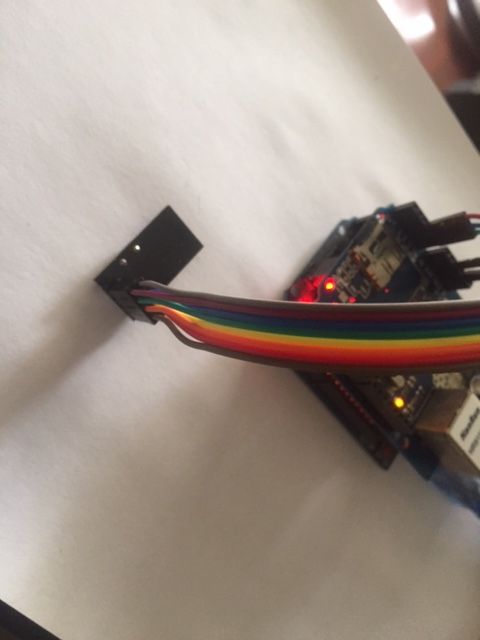
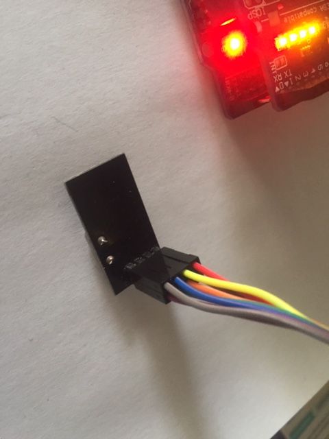
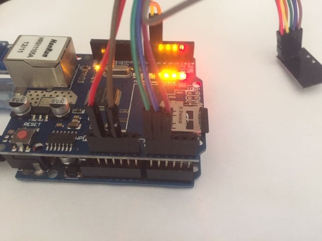
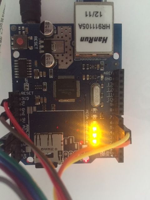
these are the real photos of the setup.
wire codes are the same as the build instructions

managing the SPI_EN signal? tried with and without, no changes.
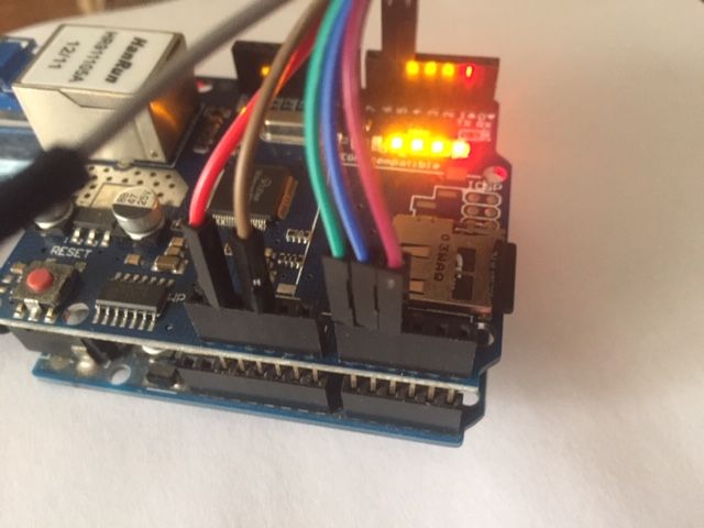
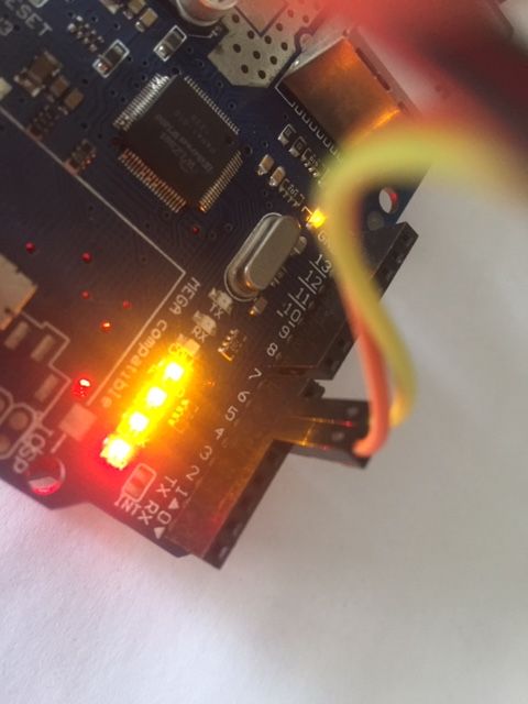
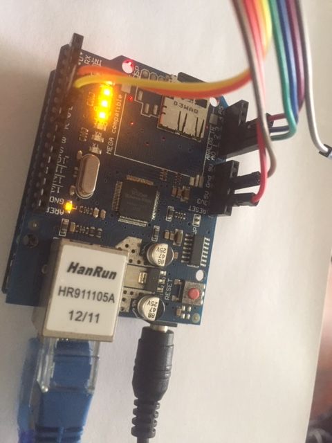
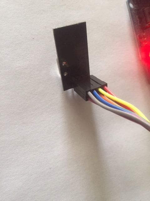
-
@pw44 you seem to have the same w5100 shield as i have. Try removing the sd card.
If that doesn't work, try my fix here : https://forum.mysensors.org/topic/9732/arduino-uno-with-ethernet-shield-w5100-not-working/10
-
@Yveaux
Thanks for the reply, removing the sd card or applying your fix did not change the problem.
-
@pw44 why are spi clk/miso/mosi connected to A0.. 2 ¿
-
@Yveaux said in Gateway Uno R3 + W5100 Ethernet Shield for Uno not working.:
@pw44 why are spi clk/miso/mosi connected to A0.. 2 ¿
as described in https://www.mysensors.org/build/ethernet_gateway
-
@pw44 said in Gateway Uno R3 + W5100 Ethernet Shield for Uno not working.:
as described in https://www.mysensors.org/build/ethernet_gateway
Yes, but the sketch just below it has
//#define MY_W5100_SPI_EN 4You actually have enabled this line, which causes the arduino to use hardware spi. And hardware spi uses different pins for clk/miso/mosi.
You wired for software spi, so comment that line as in the example.
-
thanks man, you're right. commenting out
//#define MY_W5100_SPI_EN 4solved it.
now, debug shows:
0 MCO:BGN:INIT GW,CP=RNNGA---,FQ=16,REL=255,VER=2.3.2
4 MCO:BGN:BFR
6 TSM:INIT
7 TSF:WUR:MS=0
13 TSM:INIT:TSP OK
15 TSM:INIT:GW MODE
16 TSM:READY:ID=0,PAR=0,DIS=0
19 MCO:REG:NOT NEEDED
696 GWT:TIN:IP=192.168.80.9
1699 MCO:BGN:STP
1701 MCO:BGN:INIT OK,TSP=1
1703 TSM:READY:NWD REQ
1709 ?TSF:MSG:SEND,0-0-255-255,s=255,c=3,t=20,pt=0,l=0,sg=0,ft=0,st=OK:
just another question: does the 3.3v line from Uno R# enough power to handle the RF24 radio?
Thx in advance!
-
@Yveaux and regardin IRQ from RF24, is it necessary to connect to pin2 of UNO R3?
-
@pw44 no
The IRQ pin is only required to be connected if the MY_RX_MESSAGE_BUFFER_FEATURE is defined in the sketch. Using this feature is recommended for high traffic nodes or gateways. Enabling it will result in better throughput but will require some additional memory to keep the message in memory before processing.
More information: https://www.mysensors.org/build/connect_radio and MY_RX_MESSAGE_BUFFER_FEATURE
-
@mfalkvidd
thank for the answer.i guess the UNO R3 is capable to do it, so, i tried
#define MY_RX_MESSAGE_BUFFER_FEATURE
#define MY_RF24_IRQ_PIN 3
and got the following error:
#error RF24 IRQ usage cannot be used with Soft SPIAny hint? The idea is having something like 80 nodes when all is done.
Thx
-
@pw44 unless your nodes send very frequently, you probably don’t need irq.
If you need irq, you’ll need to use hardware spi.
-
@mfalkvidd said in Gateway Uno R3 + W5100 Ethernet Shield for Uno not working.:
@pw44 unless your nodes send very frequently, you probably don’t need irq.
If you need irq, you’ll need to use hardware spi.
Ok, but just in case, how to use the hardware spi in this configurartion (sorry if it seams stupid, but i'm just a very beginner on this).
Thx for the understanding and also for educating me,.
-
@pw44 I don’t think anyone has managed to make the w5100 work on the same spi as nrf24.
-
ok, i was curious as i didn't find how to.
Anyway, is it possible to have the "RF24 IRQ" used as soft?
-
@pw44 no, mysensors doesn't need it for soft spi and won't use it