My rPi gateway suddenly stopped working, no idea what else to try...
-
Hey everyone, I have been using a Raspberry Pi 3 as a gateway, and have several sensors around the house built with Arduino. Everything has been working fine for months, until 2 days ago, out of the blue, everything stopped working.
I am using the RFM69W radio in the Arduino nodes, and the RFM69HW in the gateway. For what I can tell, everything is the same between the radio modules, with the difference that the HW variant supports using higher power, so I figured I would use this in the gateway, and the W variant in the nodes, since some are battery powered, in order to save battery. For months, this has been working flawlessly, and suddenly it stopped. It appears to be happening at the gateway, since it is unlikely 10 sensors have all stopped working at the same time. I have tried changing the RFM69HW module, changing the antenna, and even changing the Raspberry Pi altogether... nothing works. I have been using the development branch of mysensors, which has worked fine thus far, and I also have tried using the 2.3.2 release... same issue... Of course, doing a clean build and removing the /etc/mysensors.eeprom between tests...
I have built a simple "ping-pong" node, which I use to test coverage around the house. The arduino code is super simple, it only calls
bool rcv = send(msg.set(seconds), 1);to get an ACK. If it does it is counted as success, if not, it is counted as failure, it loops endlessly, sleeping 0.5 Seconds between sending, and it will show results in an LCD display, so I can move around the house. This has worked fine when I was deploying the different sensors around the house.
After compiling the mysgw in the rPi, I started and I see this log
root@openhab:/home/pi/MySensors# ./bin/mysgw
Sep 04 21:13:56 INFO  Config file /etc/mysensors.conf does not exist, creating new file.
Sep 04 21:13:56 INFO  Starting gateway...
Sep 04 21:13:56 INFO  Protocol version - 2.3.2
Sep 04 21:13:56 INFO  EEPROM file /etc/mysensors.eeprom does not exist, creating new file.
Sep 04 21:13:56 DEBUG MCO:BGN:INIT GW,CP=RPNGL--X,FQ=NA,REL=255,VER=2.3.2
Sep 04 21:13:56 DEBUG TSF:LRT:OK
Sep 04 21:13:56 DEBUG TSM:INIT
Sep 04 21:13:56 DEBUG TSF:WUR:MS=0
Sep 04 21:13:56 DEBUG TSM:INIT:TSP OK
Sep 04 21:13:56 DEBUG TSM:INIT:GW MODE
Sep 04 21:13:56 DEBUG TSM:READY:ID=0,PAR=0,DIS=0
Sep 04 21:13:56 DEBUG MCO:REG:NOT NEEDED
Sep 04 21:13:56 DEBUG Listening for connections on d~:5003
Sep 04 21:13:56 DEBUG MCO:BGN:STP
Sep 04 21:13:56 DEBUG MCO:BGN:INIT OK,TSP=1
Sep 04 21:13:56 DEBUG TSM:READY:NWD REQ
Sep 04 21:13:56 DEBUG ?TSF:MSG:SEND,0-0-255-255,s=255,c=3,t=20,pt=0,l=0,sg=0,ft=0,st=OK:
Everything looks good... Now I turn on my ping-pong node, and I see this:
Sep 04 21:14:06 DEBUG TSF:MSG:READ,220-220-255,s=255,c=3,t=7,pt=0,l=0,sg=0:
Sep 04 21:14:06 DEBUG TSF:MSG:BC
Sep 04 21:14:06 DEBUG TSF:MSG:FPAR REQ,ID=220
Sep 04 21:14:06 DEBUG TSF:PNG:SEND,TO=0
Sep 04 21:14:06 DEBUG TSF:CKU:OK
Sep 04 21:14:06 DEBUG TSF:MSG:GWL OK
Sep 04 21:14:10 DEBUG !TSF:MSG:SEND,0-0-220-220,s=255,c=3,t=8,pt=1,l=1,sg=0,ft=0,st=NACK:0
Sep 04 21:14:11 DEBUG TSF:MSG:READ,220-220-0,s=255,c=3,t=24,pt=1,l=1,sg=0:1
Sep 04 21:14:11 DEBUG TSF:MSG:PINGED,ID=220,HP=1
Sep 04 21:14:15 DEBUG !TSF:MSG:SEND,0-0-220-220,s=255,c=3,t=25,pt=1,l=1,sg=0,ft=0,st=NACK:1
Sep 04 21:14:15 DEBUG TSF:MSG:READ,220-220-0,s=255,c=3,t=15,pt=6,l=2,sg=0:0100
Sep 04 21:14:19 DEBUG !TSF:MSG:SEND,0-0-220-220,s=255,c=3,t=15,pt=6,l=2,sg=0,ft=0,st=NACK:0100
Sep 04 21:14:20 DEBUG TSF:MSG:READ,220-220-0,s=255,c=0,t=17,pt=0,l=5,sg=0:2.3.2
Sep 04 21:14:21 DEBUG TSF:MSG:READ,220-220-0,s=255,c=0,t=17,pt=0,l=5,sg=0:2.3.2
Sep 04 21:14:22 DEBUG TSF:MSG:READ,220-220-0,s=255,c=3,t=6,pt=1,l=1,sg=0:0
Sep 04 21:14:24 DEBUG TSF:MSG:READ,220-220-0,s=255,c=3,t=6,pt=1,l=1,sg=0:0
Sep 04 21:14:25 DEBUG TSF:MSG:READ,220-220-0,s=255,c=3,t=6,pt=1,l=1,sg=0:0
Sep 04 21:14:28 DEBUG TSF:MSG:READ,220-220-0,s=255,c=3,t=11,pt=0,l=14,sg=0:Ping-Pong Node
Sep 04 21:14:29 DEBUG TSF:MSG:READ,220-220-0,s=255,c=3,t=11,pt=0,l=14,sg=0:Ping-Pong Node
Sep 04 21:14:31 DEBUG TSF:MSG:READ,220-220-0,s=255,c=3,t=11,pt=0,l=14,sg=0:Ping-Pong Node
Sep 04 21:14:32 DEBUG TSF:MSG:READ,220-220-0,s=255,c=3,t=12,pt=0,l=3,sg=0:1.0
Sep 04 21:14:34 DEBUG TSF:MSG:READ,220-220-0,s=255,c=3,t=12,pt=0,l=3,sg=0:1.0
Sep 04 21:14:35 DEBUG TSF:MSG:READ,220-220-0,s=0,c=0,t=36,pt=0,l=0,sg=0:
Sep 04 21:14:36 DEBUG TSF:MSG:READ,220-220-0,s=0,c=0,t=36,pt=0,l=0,sg=0:
Sep 04 21:14:38 DEBUG TSF:MSG:READ,220-220-0,s=0,c=0,t=36,pt=0,l=0,sg=0:
So, the node is sending data just fine, and the GW is receiving data fine, and the problem occurs when the GW attempts to send data back to the node... Now, this could mean the RFM69HW module broke down, or the antenna is broken, or even that something in the rPi GPIO pins or whatever broke down... but being that I have pretty much replaced every single part of it with brand new stuff... brand new rpi, brand new RFM69HW, brand new antenna... and I continue to experience this... Does anyone have ANY suggestion on what to try next? I am a bit clueless here... and any advice is greatly appreciated.
Thanks all,
Franco -
Thanks a lot! that's the only thing I haven't tried... I assumed that since the raspberry pi was working fine, the internal power regulator was providing enough juice to the module through the gpio pins...
This is quite weird, I replaced the power supply, everything started worked fine. So I said, let's try the old power supply again, it should be broken... Everything is working fine too... This is quite insane.
Also, I found https://www.raspberrypi.org/forums/viewtopic.php?t=190584 and I ran that in my rpi, and I get 0x0 with both power supplies
# vcgencmd get_throttled
throttled=0x0
According to https://forum.libreelec.tv/thread/17860-how-to-interpret-rpi-vcgencmd-get-throttled/, 0x0 means all is fine with the power supply, so not sure what is going on...
I will leave it running for some hours and see what happens...
-
I would look at 2 things here -
One, test all dupont connecters at both ends for a secure connection - I spent a loooong time chasing my tail due to dupont cables that were loose. Crimp them up with pliers if you have to.
Two, what power supply are you using? 'how are you powering the gateway and pi? What voltages do you get and are there any fluctuations when the GW radio is transmitting?
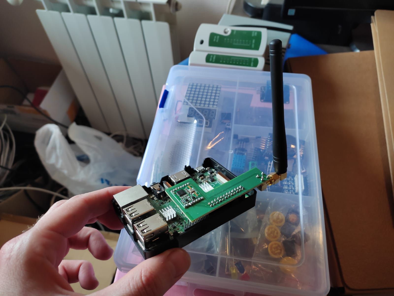
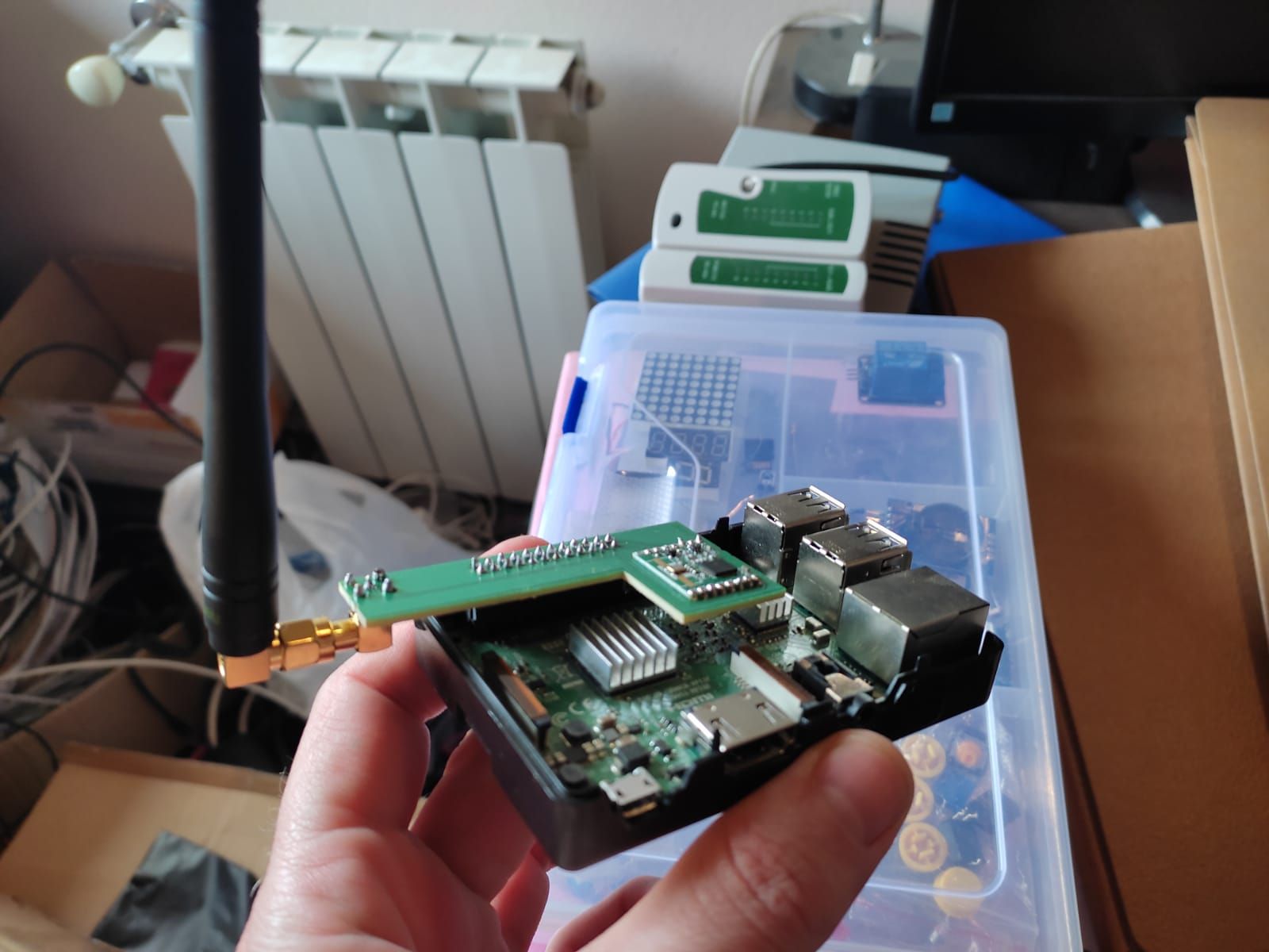
@skywatch Yeah, I have spent a lot of time fighting those as well, however in my case, I have designed a special PCB, which connects directly to the GPIO pins in the rPi, which should avoid these issues:
As per the power supply, I have been using a PSU from the same people I buy the rPi from, which is a 5VCC, 3.1A, for months until this started happening. After @Yveaux suggestion, I tried my pixel charger, which should deliver 5V - 3A, and as I said, it worked fine for about 10 hours straight, but then stopped working again. Furthermore, the rPi is not reporting undervoltage or throttling, so not sure if it is the PSU at all... I don't want to take appart the PSU, but if there are no more ideas on what else might be, I guess I'll have no choice...
-
@skywatch Yeah, I have spent a lot of time fighting those as well, however in my case, I have designed a special PCB, which connects directly to the GPIO pins in the rPi, which should avoid these issues:
As per the power supply, I have been using a PSU from the same people I buy the rPi from, which is a 5VCC, 3.1A, for months until this started happening. After @Yveaux suggestion, I tried my pixel charger, which should deliver 5V - 3A, and as I said, it worked fine for about 10 hours straight, but then stopped working again. Furthermore, the rPi is not reporting undervoltage or throttling, so not sure if it is the PSU at all... I don't want to take appart the PSU, but if there are no more ideas on what else might be, I guess I'll have no choice...
@frapell I have the same network/phone cable tester as in the phto!- Hahaha.....
Back to the probem it does sound as if something is changing over time, that is why I suspect power supply, cables or connections. I guess you checked for dry joints on the pcb, vut it would be worth checking ecery pin has a firm connection with a multimeter and a spare dupont pin. Temperature difference can make a bigger difference then most people think.
Is the radion module connected to 5V on pi or 3.3V? this is another possible area to look at but I need to know this first...
finally, with good dupont cables, remove your pcb from the pi and connect it again using dupont wires 150mm or more away from the pi and try that. I am wondering if the RF path to the antenna being close to the gpio and cpu might perhaps be possible culprit. Is there any screening on the back of the pcb ?
-
@frapell I have the same network/phone cable tester as in the phto!- Hahaha.....
Back to the probem it does sound as if something is changing over time, that is why I suspect power supply, cables or connections. I guess you checked for dry joints on the pcb, vut it would be worth checking ecery pin has a firm connection with a multimeter and a spare dupont pin. Temperature difference can make a bigger difference then most people think.
Is the radion module connected to 5V on pi or 3.3V? this is another possible area to look at but I need to know this first...
finally, with good dupont cables, remove your pcb from the pi and connect it again using dupont wires 150mm or more away from the pi and try that. I am wondering if the RF path to the antenna being close to the gpio and cpu might perhaps be possible culprit. Is there any screening on the back of the pcb ?
@skywatch Heheh, yeah, a friend gave it to me in a software conference back in 2014, very useful when testing you clamped everything fine a couple of rooms away ;)
it does sound as if something is changing over time, that is why I suspect power supply, cables or connections.
Yeah, it is weird though since the rPi has been in the same table for months... it is even plugged to an APC UPS, so there should be no outages or anything in the main lines messing with the PSU.
I guess you checked for dry joints on the pcb, vut it would be worth checking ecery pin has a firm connection with a multimeter and a spare dupont pin.
Yup, I have 4 PCB's built in the exact same way, 4 RFM69HW and 4 antennas. I have tried each 4 with the same rPi and with a spare one I have... same thing... The only thing I haven't tried yet (which I guess I need to do) is formatting the SD card and starting from scratch... I really don't see why this would fix it, since it has been running the exact same software since... I haven't even updated packages (I have done so since the issues started occurring, to no avail)
Is the radio module connected to 5V on pi or 3.3V? this is another possible area to look at but I need to know this first...
It is connected exactly as described in https://www.mysensors.org/build/raspberry#wiring for the RFM69, so 3.3V.
One thing with this that I am not 100% sure, is that there are 2 flags described in https://www.mysensors.org/apidocs/group__RaspberryPiGateway.html the
--my-rfm69-irq-pinand--my-rfm69-cs-pinI am not sure if I should specify a pin for this when wiring as suggested... And if I do, I don't know which pins are CS and IRQ in the RFM69.I put another question a couple of months ago in https://forum.mysensors.org/topic/11716/having-problems-with-rfm69hw-in-raspberry-pi but the problem eventually went away (not sure why), so it seems they are not needed. (Also I switched from MQTT to Ethernet)
finally, with good dupont cables, remove your pcb from the pi and connect it again using dupont wires 150mm or more away from the pi and try that. I am wondering if the RF path to the antenna being close to the gpio and cpu might perhaps be possible culprit. Is there any screening on the back of the pcb ?
No, this is a 1 sided PCB. I will try your suggestions, hopefully tonight, since cannot right now. Sounds kind of weird that the antenna path would be an issue since it has been working fine for months, with a range that went over my expectations (More than 30m away, behind 4 walls)... One thing I am not sure if I built fine in the PCB, you can see that the RF Connector has the center connection to the antenna path going to the "ANA" in the RFM69 chip, however the 4 angles of the RF connector, are soldered to GND, my understanding is that this is correct, can you confirm?
-
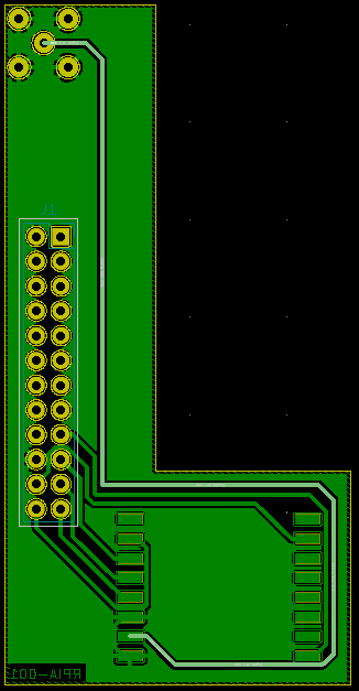
@skywatch I found a way to enable flags to get more debug info both for the RFM69 as for the Transport HAL in order to try and get more info on what the software see when it is broken, and the thing has been working fine for 2 days straight now... Go figure... So I am wondering (Attaching the custom PCB design below):
Some questions:
-
I have highlighted the via for the antenna, could it be too long and it was maybe picking up some interference? I am thinking on moving the RFM69 module to be up there, as close as possible to the SMA connector as possible...
-
What do you think about the via thickness? should I make it wider? it is 0.4mm right now
-
Is it ok that the 4 corners for the SMA connector are connected to GND? I believe it is ok, right?
-
-
Just a warning upfront - I'm an engineer, but not an RF engineer, so I do see some things, but I'm almost guaranteed to miss others.
As far as your highlighted line, it is a trace, but not a via. A via connects the trace on one plane of copper with a trace on another plane.
That trace should really be as short and direct as possible. Wrapping around the back of the module and along other signal lines is not a good idea. I see that the closest line to it is 3.3V power, so that acts basically as ground for small signal, but any power spike is bound to couple into the antenna line as well, at least some. If possible, it would be best to have ground on both sides of the antenna trace on that side of the board, as well as the whole surface on the other side of the board from it. Might also want to guard it by having vias connect the ground planes on either side of it to make kind of a 3d cage around it.
Additionally, you should try for 50 ohm trace impedance on the antenna line. However, there is no one-size-fits-all answer for the width of this line. It depends on the exact board parameters, and even to a small amount on the frequency of the signal. There are trace width impedance calculators that you can use to get this answer. https://resources.pcb.cadence.com/blog/2019-just-how-wide-should-a-pcb-50-ohm-trace-width-be
Almost guaranteed that it's correct to ground those 4 outer pins of the antenna connector. View the datasheet of the specific connector you are using to be 100% sure.
-
@skywatch I found a way to enable flags to get more debug info both for the RFM69 as for the Transport HAL in order to try and get more info on what the software see when it is broken, and the thing has been working fine for 2 days straight now... Go figure... So I am wondering (Attaching the custom PCB design below):
Some questions:
-
I have highlighted the via for the antenna, could it be too long and it was maybe picking up some interference? I am thinking on moving the RFM69 module to be up there, as close as possible to the SMA connector as possible...
-
What do you think about the via thickness? should I make it wider? it is 0.4mm right now
-
Is it ok that the 4 corners for the SMA connector are connected to GND? I believe it is ok, right?
@frapell If you can, get some small coax cable for wifi use and use that instead of the track on the PCB- Make sure it is grounded at the sending end - As for the power, I strongly suggest making a 5v to 3.3V regulator as the pi 3.3v can be quite 'noisey' - a buck regulater will help reduve this a lot. Don't forget capacitors on the input and output of the neg board. I did this for my pi set up too as it has the advantage of the radio getting power from the psu and not cia the pi. A linear regulator like the AMS1117 will do the trick.
-
-
Just a warning upfront - I'm an engineer, but not an RF engineer, so I do see some things, but I'm almost guaranteed to miss others.
As far as your highlighted line, it is a trace, but not a via. A via connects the trace on one plane of copper with a trace on another plane.
That trace should really be as short and direct as possible. Wrapping around the back of the module and along other signal lines is not a good idea. I see that the closest line to it is 3.3V power, so that acts basically as ground for small signal, but any power spike is bound to couple into the antenna line as well, at least some. If possible, it would be best to have ground on both sides of the antenna trace on that side of the board, as well as the whole surface on the other side of the board from it. Might also want to guard it by having vias connect the ground planes on either side of it to make kind of a 3d cage around it.
Additionally, you should try for 50 ohm trace impedance on the antenna line. However, there is no one-size-fits-all answer for the width of this line. It depends on the exact board parameters, and even to a small amount on the frequency of the signal. There are trace width impedance calculators that you can use to get this answer. https://resources.pcb.cadence.com/blog/2019-just-how-wide-should-a-pcb-50-ohm-trace-width-be
Almost guaranteed that it's correct to ground those 4 outer pins of the antenna connector. View the datasheet of the specific connector you are using to be 100% sure.
@ejlane Well, I am a software developer myself (Not engineer, and certainly not RF engineer) And by looking at my design it is clear that I can barely consider myself an electronic hobbyist :sweat_smile:
Thanks a lot for your suggestions, This is a very basic one-sided PCB I designed in order to avoid having wires, which I thought was worse... I will redesign the whole thing and will post back (If you have more suggestions, I will be more than pleased to know)
@skywatch I am trying to make this as simple as possible, and to be able to fit inside a rPi case, so I will try to get the trace as short as possible between the module and the SMA for now, and see how it goes. As per your AMS1117 suggestion, I am assuming you mean instead of getting 3.3v pin from the GPIO, use the 5V one and go through an AMS1117 to get 3.3v, right? Also, about the capacitor, may I ask what exactly is the "neg board" ?
-
@ejlane Well, I am a software developer myself (Not engineer, and certainly not RF engineer) And by looking at my design it is clear that I can barely consider myself an electronic hobbyist :sweat_smile:
Thanks a lot for your suggestions, This is a very basic one-sided PCB I designed in order to avoid having wires, which I thought was worse... I will redesign the whole thing and will post back (If you have more suggestions, I will be more than pleased to know)
@skywatch I am trying to make this as simple as possible, and to be able to fit inside a rPi case, so I will try to get the trace as short as possible between the module and the SMA for now, and see how it goes. As per your AMS1117 suggestion, I am assuming you mean instead of getting 3.3v pin from the GPIO, use the 5V one and go through an AMS1117 to get 3.3v, right? Also, about the capacitor, may I ask what exactly is the "neg board" ?
@frapell neg board should have been reg board (as in the regulator to go from 5 to 3.3V - When I did this a lot of issues I had went away. Take the 5V supply from the power supply input to the raspberry pi board. This means any current surge will be provided by the power supply and not from the pi itselff. I hope that makes sense.
-
@frapell neg board should have been reg board (as in the regulator to go from 5 to 3.3V - When I did this a lot of issues I had went away. Take the 5V supply from the power supply input to the raspberry pi board. This means any current surge will be provided by the power supply and not from the pi itselff. I hope that makes sense.
@skywatch Ahhh, makes sense now :) thanks!
@ejlane I got the specifications from the PCB manufacturer (Attaching below), and the copper thickness is 35 microns...
I managed to get the module with the antenna pin right next to the connector, so the trace length would be just 4mm, for what I was able to find, my case for a single sided PCB would be a "Coplanar wave guide" and plugging all of those values in a calculator I found in KiCAD, it seems that I am fine with a 1 mm wide trace, with a 0.25mm gap with the GND around it.Hope I got it right! Thank you for your suggestions!

-
I think your numbers look good. Nice job getting the trace much shorter - that should help a bunch.
Oh, and Skywatch's tips are also good. Solid power is very important. I would put a few different capacitors as close to the power pin of the radio module as possible. 100n, and then a selection from: 1u, 4.7u, and 10u. I would likely go with 2 of those microfarad capacitors, and maybe all three. I like to err on the side of overkill where power capacitors are involved.
-
@ejlane @Yveaux @skywatch So, I have found exactly what was going on, and had nothing to do with the hardware... Basically, one of my nodes was jamming the radio channel :face_with_rolling_eyes:
How I discovered the issue:
There are 2 more flags, besidesMY_DEBUGwhich areMY_DEBUG_VERBOSE_RFM69andMY_DEBUG_VERBOSE_TRANSPORT_HALwhich I couldn't find a way to add, so I did it by editing theconfigurescript and where it saysif [[ ${debug} == "enable" ]]; then CPPFLAGS="-DMY_DEBUG $CPPFLAGS" fiI changed it for
if [[ ${debug} == "enable" ]]; then
    CPPFLAGS="-DMY_DEBUG -DMY_DEBUG_VERBOSE_RFM69 -DMY_DEBUG_VERBOSE_TRANSPORT_HAL $CPPFLAGS"
fi
Then re-ran the script and recompiled the
mysgwbinary. The important flag in my case wasMY_DEBUG_VERBOSE_RFM69.When
mysgwwas running, and everything was working fine, I was seeing lines withDEBUG RFM69:CSMA:RSSI=-102popping in once or twice (with different values forRSSI) and everything continued normally. Then, when the whole thing was wedged and nothing worked, I noticed that message pretty much going on foreverSep 09 18:37:11 DEBUG RFM69:CSMA:RSSI=-52 Sep 09 18:37:11 DEBUG RFM69:CSMA:RSSI=-52 Sep 09 18:37:11 DEBUG RFM69:CSMA:RSSI=-53 Sep 09 18:37:11 DEBUG RFM69:CSMA:RSSI=-52 Sep 09 18:37:11 DEBUG RFM69:CSMA:RSSI=-52 Sep 09 18:37:11 DEBUG RFM69:CSMA:RSSI=-53And on and on and on.... forever... Clearly there was a loop somewhere for whatever reason printing this message. As it turns out, there's a function that the RFM69 driver calls before sending a message https://github.com/mysensors/MySensors/blob/2e00bf6a10f76d6aaa1999e12313237bc3edabd3/hal/transport/RFM69/driver/new/RFM69_new.cpp#L369-L375 that pretty much checks if there is noise in the RF channel, before actually sending anything...
I was doing some modifications to one node I have, where I replaced the arduino with another one, which I thought was a 3.3v one, burned it as so, but it was a 5v. For whatever reason (maybe the different clock speed? dunno...) when doing that, the node will send garbage through the radio... I have no idea how it manages to init the radio... doesn't really matter, the thing was sending something in the same channel constantly...And that is why the gateway was receiving data from other nodes, but was never able to send back... this other node was preventing it because it would never shut up... I have now replaced the arduino with a 3.3v one, checked in the serial monitor after burning :wink: and re-installed, and everything is back to normal and working...
Thank you all for your help and suggestions, I will nevertheless build the new PCB with the suggested changes and replace the ones I am currently using.
-
Great work everyone! I have been following this thread and it makes me very happy to see how you work together.
For the debug flags, check out the ”Advanced” section at https://www.mysensors.org/build/raspberry#advanced
@mfalkvidd Totally missed that! sweet !
-
mfalkvidd gave you a great link, but if you ever need to see any possible choices, you can run
./configure --helpand it will show you. The extra flags section is one thing (of many) that it says.
Actually, this is very timely for me, as I'm trying to troubleshoot my own radio issues, so I'll use those extra two flags that you mentioned and see what they say.
Thank you!
Hello! It looks like you're interested in this conversation, but you don't have an account yet.
Getting fed up of having to scroll through the same posts each visit? When you register for an account, you'll always come back to exactly where you were before, and choose to be notified of new replies (either via email, or push notification). You'll also be able to save bookmarks and upvote posts to show your appreciation to other community members.
With your input, this post could be even better 💗
Register Login