💬 Easy/Newbie PCB for MySensors
-
Sorry, I'm a bit slow and maybe a little off-topic: A quicky:
Can I read somewhere how payment is done when ordering from openhardware.io? On the start page for openhardware.io there is no clue. I've also tried to search this section (easy-newbie-pcb-for-mysensors) for "payment".
Yes, I've read that the "order" is more like a forward of orderinformation to the supplier, but do I really need to order first and after that ask what payment solution is present?
:)
A complete rookie! Love this stuff! My path: Domoticz/Zwave and now a big MySensors-fan! :)
-
Sorry, I'm a bit slow and maybe a little off-topic: A quicky:
Can I read somewhere how payment is done when ordering from openhardware.io? On the start page for openhardware.io there is no clue. I've also tried to search this section (easy-newbie-pcb-for-mysensors) for "payment".
Yes, I've read that the "order" is more like a forward of orderinformation to the supplier, but do I really need to order first and after that ask what payment solution is present?
:)
@pellusfromtellus - to get a 100% right answer we ping @hek but I recommend paypal!
-
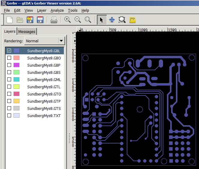
Is there a drilling and outline file available?
-
Is there a drilling and outline file available?
@Paul-Robertson - hi!
Yes, but this is Eagles output gerber files.Drill: SundbergMys9.TXT
Outline can be found in all other files:https://www.pcbway.com/project/share/How_to_generate_Gerber_from_Eagle.html
-
Damn. Just missing the 0,1uF capacitor ..... to complete the 5v build. This will be my smallest build yet ;-) using PCB v9
-
IS it possible to use TP4056 (https://www.aliexpress.com/item/5-pcs-Micro-USB-5V-1A-18650-TP4056-Lithium-Battery-Charger-Module-Charging-Board-With-Protection/32728720869.html?spm=a2g0s.9042311.0.0.A0lkC7) this instead of using the step up booster?
Thanks!! -
IS it possible to use TP4056 (https://www.aliexpress.com/item/5-pcs-Micro-USB-5V-1A-18650-TP4056-Lithium-Battery-Charger-Module-Charging-Board-With-Protection/32728720869.html?spm=a2g0s.9042311.0.0.A0lkC7) this instead of using the step up booster?
Thanks!!@hiddenuser - well not out of the box as mentioned by gohan. Im not really sure what you want to do. Its not possible to use this instead of step-up booster since it outputs 5v and the step-up needs to output 3.3v. But with a voltage regulator in between maybe? As I said - don really understand so maybe you can explain some more about your project?
Controller: Proxmox VM - Home Assistant
MySensors GW: Arduino Uno - W5100 Ethernet, Gw Shield Nrf24l01+ 2,4Ghz
MySensors GW: Arduino Uno - Gw Shield RFM69, 433mhz
RFLink GW - Arduino Mega + RFLink Shield, 433mhz -
@hiddenuser - well not out of the box as mentioned by gohan. Im not really sure what you want to do. Its not possible to use this instead of step-up booster since it outputs 5v and the step-up needs to output 3.3v. But with a voltage regulator in between maybe? As I said - don really understand so maybe you can explain some more about your project?
-
Thanks @sundberg84 and @gohan
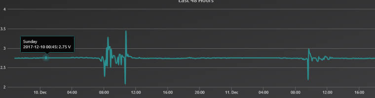
I have used made the board for 3.3v set up as per the instruction. I have usd the output from tp4056 into the Battery connector of the board I have a step board from https://www.aliexpress.com/item/New-Electric-Unit-1-PC-NEW-DC-0-8-3-3V-to-DC-3-3V-StepUP/32724361266.html According to the specification given in the same link it is supposed to stabilize to 3.3v above 3v but the sensor reports something else back to the gateway.
-
Thanks @sundberg84 and @gohan
I have used made the board for 3.3v set up as per the instruction. I have usd the output from tp4056 into the Battery connector of the board I have a step board from https://www.aliexpress.com/item/New-Electric-Unit-1-PC-NEW-DC-0-8-3-3V-to-DC-3-3V-StepUP/32724361266.html According to the specification given in the same link it is supposed to stabilize to 3.3v above 3v but the sensor reports something else back to the gateway.
@hiddenuser - well, what would a battery measurer be if it reported a constant 3.3v boosted voltage? ;)
It all depends on how everything is connected (pictures?) but if you have connected it as battery instryctions the radio and voltage divider that measured the incoming battery are not a part of the booster circuit. This to prevent noice to the radio and to be able to actually measure the battery voltage and not step-up voltage which is the idea behind the board. -
Thanks @sundberg84 and @gohan
I have used made the board for 3.3v set up as per the instruction. I have usd the output from tp4056 into the Battery connector of the board I have a step board from https://www.aliexpress.com/item/New-Electric-Unit-1-PC-NEW-DC-0-8-3-3V-to-DC-3-3V-StepUP/32724361266.html According to the specification given in the same link it is supposed to stabilize to 3.3v above 3v but the sensor reports something else back to the gateway.
-
@sundberg84 interesting question...or maybe stupid question not sure...
i have a tonn of 3v pro mini's but im thinking of mains powering some for motion sensors.... would i set it up as battery, and then just use a voltage regulator on where the step up usually would be? or is there a better way to handle it?
-
@gohan The only voltage regulator that I know of on the board is mainly for the radio. Unless you are talking the one on the pro mini.
@markjgabb If you want to do them from mains power, you might wan t to look at the HLK modules like these
https://www.ebay.com/itm/1Pcs-Power-Supply-Step-Down-Buck-Isolated-Hlk-Pm03-220V-To-3-3V-Module-New-Ic-N/332047987473?epid=571729397&hash=item4d4f9a3311:g:nyMAAOSw4GVYPa8q
Otherwise an old phone charger should work. -
@gohan The only voltage regulator that I know of on the board is mainly for the radio. Unless you are talking the one on the pro mini.
@markjgabb If you want to do them from mains power, you might wan t to look at the HLK modules like these
https://www.ebay.com/itm/1Pcs-Power-Supply-Step-Down-Buck-Isolated-Hlk-Pm03-220V-To-3-3V-Module-New-Ic-N/332047987473?epid=571729397&hash=item4d4f9a3311:g:nyMAAOSw4GVYPa8q
Otherwise an old phone charger should work.