RGB LED strip amplifier gives inverted RGB value
-
Hi all
Insteads of using three Mosfet, I have connected my RGB led strip with my arduino using a RGB mini amplifier (see below). Since it is smaller and you don't have to solder any wires. I am able to control the led strip in Domoticz but the only problem is the RGB value is inverted. So when you choose blue in the colorpicker the led turns yellow. When you dim the light to 10% it is at its full brightness and when you set the level to 100% it turns off. (So the values are inverts). I have tested with a single dimmable led strip and it gave me the same result. It looks like that this module works as an inverted Mosfet.

Anyway I was wondering if you can solve this problem by modifying the script I am using. Like may be inverting the value.
This is the script I am using
#include <MySensor.h>
#include <SPI.h>

#define RED_PIN 3
#define GREEN_PIN 5
#define BLUE_PIN 6

#define NODE_ID 70
#define CHILD_ID 0
#define SKETCH_NAME "RGB_STRIP "
#define SKETCH_VERSION "1.0.0"
#define NODE_REPEAT false

MySensor gw;

long RGB_values[3] = {0, 0, 0};
float dimmer;

void setup() {


  pinMode(RED_PIN, OUTPUT);
  pinMode(GREEN_PIN, OUTPUT);
  pinMode(BLUE_PIN, OUTPUT);

  gw.begin(incomingMessage, NODE_ID, NODE_REPEAT, 0);
  gw.sendSketchInfo(SKETCH_NAME, SKETCH_VERSION);
  gw.present(CHILD_ID, S_RGB_LIGHT, "RGB Strip", false);
  gw.request(CHILD_ID, V_RGB);
}

void loop() {
  gw.process();
}

void incomingMessage(const MyMessage &message) {

  if (message.type == V_RGB) {

    String hexstring = message.getString();
    long number = (long) strtol( &hexstring[0], NULL, 16);
    RGB_values[0] = number >> 16;
    RGB_values[1] = number >> 8 & 0xFF;
    RGB_values[2] = number & 0xFF;
  }
  if (message.type == V_DIMMER) {
    dimmer = message.getInt();
    analogWrite(RED_PIN, int(RGB_values[0] * (dimmer / 100)));
    analogWrite(GREEN_PIN, int(RGB_values[1] * (dimmer / 100)));
    analogWrite(BLUE_PIN, int(RGB_values[2] * (dimmer / 100)));
  }

  if (message.type == V_LIGHT) {
    if (message.getInt() == 0) {
      digitalWrite(RED_PIN, 0);
      digitalWrite(GREEN_PIN, 0);
      digitalWrite(BLUE_PIN, 0);

    }
    if (message.getInt() == 1) {
      analogWrite(RED_PIN, int(RGB_values[0] * (dimmer / 100)));
      analogWrite(GREEN_PIN, int(RGB_values[1] * (dimmer / 100)));
      analogWrite(BLUE_PIN, int(RGB_values[2] * (dimmer / 100)));
    }
  }
}
Thanks
-
Hi all
Insteads of using three Mosfet, I have connected my RGB led strip with my arduino using a RGB mini amplifier (see below). Since it is smaller and you don't have to solder any wires. I am able to control the led strip in Domoticz but the only problem is the RGB value is inverted. So when you choose blue in the colorpicker the led turns yellow. When you dim the light to 10% it is at its full brightness and when you set the level to 100% it turns off. (So the values are inverts). I have tested with a single dimmable led strip and it gave me the same result. It looks like that this module works as an inverted Mosfet.
Anyway I was wondering if you can solve this problem by modifying the script I am using. Like may be inverting the value.
This is the script I am using
#include <MySensor.h>
#include <SPI.h>

#define RED_PIN 3
#define GREEN_PIN 5
#define BLUE_PIN 6

#define NODE_ID 70
#define CHILD_ID 0
#define SKETCH_NAME "RGB_STRIP "
#define SKETCH_VERSION "1.0.0"
#define NODE_REPEAT false

MySensor gw;

long RGB_values[3] = {0, 0, 0};
float dimmer;

void setup() {


  pinMode(RED_PIN, OUTPUT);
  pinMode(GREEN_PIN, OUTPUT);
  pinMode(BLUE_PIN, OUTPUT);

  gw.begin(incomingMessage, NODE_ID, NODE_REPEAT, 0);
  gw.sendSketchInfo(SKETCH_NAME, SKETCH_VERSION);
  gw.present(CHILD_ID, S_RGB_LIGHT, "RGB Strip", false);
  gw.request(CHILD_ID, V_RGB);
}

void loop() {
  gw.process();
}

void incomingMessage(const MyMessage &message) {

  if (message.type == V_RGB) {

    String hexstring = message.getString();
    long number = (long) strtol( &hexstring[0], NULL, 16);
    RGB_values[0] = number >> 16;
    RGB_values[1] = number >> 8 & 0xFF;
    RGB_values[2] = number & 0xFF;
  }
  if (message.type == V_DIMMER) {
    dimmer = message.getInt();
    analogWrite(RED_PIN, int(RGB_values[0] * (dimmer / 100)));
    analogWrite(GREEN_PIN, int(RGB_values[1] * (dimmer / 100)));
    analogWrite(BLUE_PIN, int(RGB_values[2] * (dimmer / 100)));
  }

  if (message.type == V_LIGHT) {
    if (message.getInt() == 0) {
      digitalWrite(RED_PIN, 0);
      digitalWrite(GREEN_PIN, 0);
      digitalWrite(BLUE_PIN, 0);

    }
    if (message.getInt() == 1) {
      analogWrite(RED_PIN, int(RGB_values[0] * (dimmer / 100)));
      analogWrite(GREEN_PIN, int(RGB_values[1] * (dimmer / 100)));
      analogWrite(BLUE_PIN, int(RGB_values[2] * (dimmer / 100)));
    }
  }
}
Thanks
@Chakkie Hmmm it sounds odd. But if the software part can easily be changed. I'm not able to test it but this is what I would do. I'm not gonna modify the complete sketch. But I'd use an unsigned byte as the storage type for the RGB values. It uses less memory, but that's the only reason.
void incomingMessage(const MyMessage &message) {

  if (message.type == V_RGB) {

    String hexstring = message.getString();
    long number = (long) strtol( &hexstring[0], NULL, 16);
    RGB_values[0] = 254 - ( number >> 16 );
    RGB_values[1] = 254 - ( number >> 8 & 0xFF );
    RGB_values[2] = 254 - ( number & 0xFF );
  }
  else if (message.type == V_DIMMER) {
    dimmer = message.getInt();
    analogWrite(RED_PIN, int(RGB_values[0] * (dimmer / 100)));
    analogWrite(GREEN_PIN, int(RGB_values[1] * (dimmer / 100)));
    analogWrite(BLUE_PIN, int(RGB_values[2] * (dimmer / 100)));
  }
  else if (message.type == V_LIGHT) {
    analogWrite( RED_PIN, message.getBool() == true ? 0 : int(RGB_values[0] * (dimmer / 100)) );
    analogWrite( GREEN_PIN, message.getBool() == true ? 0 : int(RGB_values[1] * (dimmer / 100)) );
    analogWrite( BLUE_PIN, message.getBool() == true ? 0 : int(RGB_values[2] * (dimmer / 100)) );
 }
  }
}
I've refactored the code a bit. As said I can't test it and haven't compiled it. But I hope it works and that it'll help you a bit in the good direction.
ps. I didn't like soldering in the beginning but once you've mastered it is - to me at least - more satisfying to solder my own projects.
Anyway good luck with it
-
@Chakkie Hmmm it sounds odd. But if the software part can easily be changed. I'm not able to test it but this is what I would do. I'm not gonna modify the complete sketch. But I'd use an unsigned byte as the storage type for the RGB values. It uses less memory, but that's the only reason.
void incomingMessage(const MyMessage &message) {

  if (message.type == V_RGB) {

    String hexstring = message.getString();
    long number = (long) strtol( &hexstring[0], NULL, 16);
    RGB_values[0] = 254 - ( number >> 16 );
    RGB_values[1] = 254 - ( number >> 8 & 0xFF );
    RGB_values[2] = 254 - ( number & 0xFF );
  }
  else if (message.type == V_DIMMER) {
    dimmer = message.getInt();
    analogWrite(RED_PIN, int(RGB_values[0] * (dimmer / 100)));
    analogWrite(GREEN_PIN, int(RGB_values[1] * (dimmer / 100)));
    analogWrite(BLUE_PIN, int(RGB_values[2] * (dimmer / 100)));
  }
  else if (message.type == V_LIGHT) {
    analogWrite( RED_PIN, message.getBool() == true ? 0 : int(RGB_values[0] * (dimmer / 100)) );
    analogWrite( GREEN_PIN, message.getBool() == true ? 0 : int(RGB_values[1] * (dimmer / 100)) );
    analogWrite( BLUE_PIN, message.getBool() == true ? 0 : int(RGB_values[2] * (dimmer / 100)) );
 }
  }
}
I've refactored the code a bit. As said I can't test it and haven't compiled it. But I hope it works and that it'll help you a bit in the good direction.
ps. I didn't like soldering in the beginning but once you've mastered it is - to me at least - more satisfying to solder my own projects.
Anyway good luck with it
Thank you so much TheoL. With your help I have added the 254 value as you told me. Once uploaded I can see that the color is closer to color I picked. So I have changed 254 to 255 and yes I 've got the right color. Now comes the next problem. I can no longer dim or turn off the led strip. When ever I choose the white ffffff or black 000000. The led stays at it full brightness. I guess we are close but only a little more tweak.
Thanks you so much
-
Hi TheoL,
I have changed the value from 0 to 255 as shown below and now the LED strip turn off when I click the off button in domoticz.
Now the dimming part has yet to be solved :)

Was
 if (message.type == V_LIGHT) {
    if (message.getInt() == 0) {
      digitalWrite(RED_PIN, 255);
      digitalWrite(GREEN_PIN, 255);
      digitalWrite(BLUE_PIN, 255);```
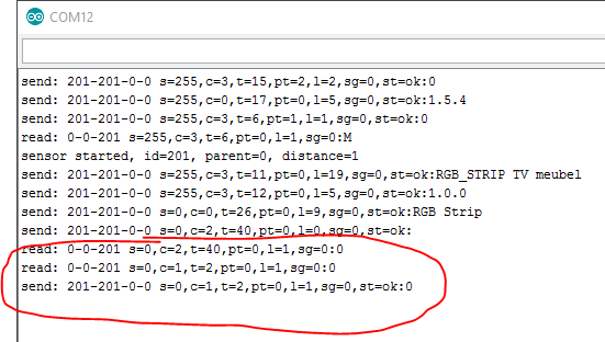
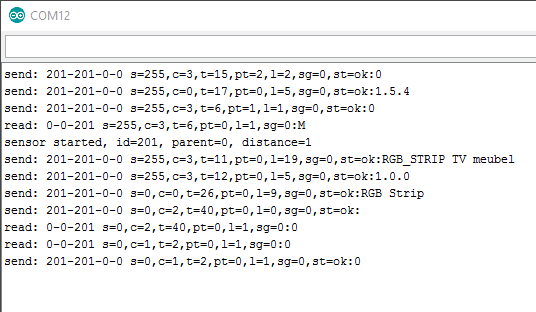 image url)
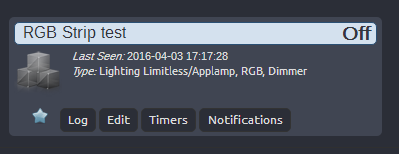 image url)
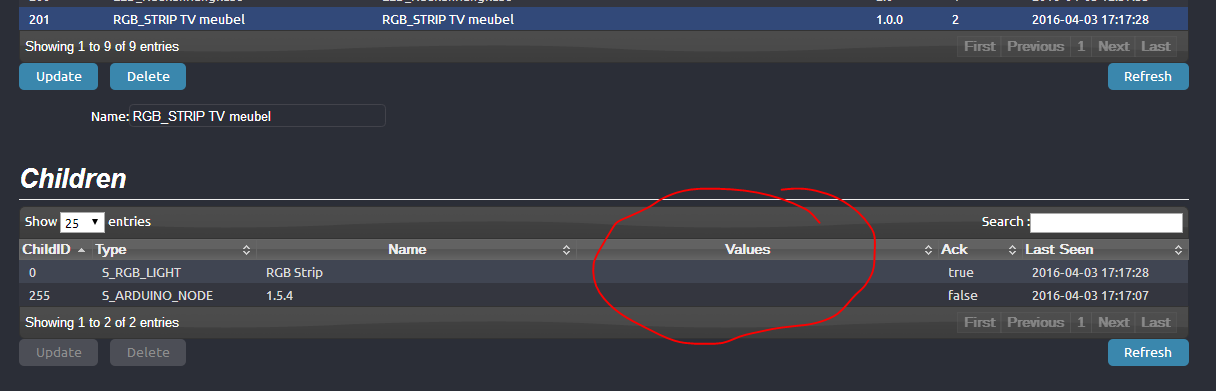 image url)
Hello! It looks like you're interested in this conversation, but you don't have an account yet.
Getting fed up of having to scroll through the same posts each visit? When you register for an account, you'll always come back to exactly where you were before, and choose to be notified of new replies (either via email, or push notification). You'll also be able to save bookmarks and upvote posts to show your appreciation to other community members.
With your input, this post could be even better 💗
Register Login